Schwinn Z Operating instructions

Page 1
637-8808 Rev. J
Technical Procedure
Schwinn X/Z Troubleshooting & Replacement
Applies to: Schwinn X (9-7470 + 9-7480), Schwinn Z (9-7510 + 9-7520)
Enhanced Images: Pictures can be zoomed in to any level for
detail. Use the standard zoom tools for your platform to zoom in.
This document covers procedures for the Schwinn Z and X bikes. The Schwinn Z is pictured, procedures are
applicable for the Schwinn X cycle except where specified. Click on procedure below to jump to section:
Fore-Aft Adjustment Lever Replacement ...................................................... 2
Tighten Loose Handlebars or Seat................................................................. 7
Handlebars 7
Seat 8
Cycle Belt and Flywheel Replacement......................................................... 10
Z Bike Gear-Angle Sensor Replacement ..................................................... 16
Z Bike LED Board Replacement ................................................................. 19
Z Bike Battery Replacement ................................................................. 22
Bike Battery Replacement 22
4iiii Crank Arm Battery Replacement 23
Crank Removal............................................................................................. 24
Pedal Removal............................ ................................................................. 25
Flywheel Position Adjustment ................................................................. 26

Page 2
637-8808 Rev. J
Technical Procedure
Fore-Aft Adjustment Lever Replacement
Required Tools:
• 4mm Allen Key
• 5mm Allen Key
• Ratchet Wrench
• 11mm Deep Socket
• Torque Wrench
• #2 Phillips Screwdriver
Required Parts*:
• For seat: 727-0177-XX “ASSY, CAM LEVER, SEAT, ACPU”
• For seat: 300-0245 “BLOCK, GAUGE, TORQUE, SEAT, UGC”*
• For handlebars: 727-0176-XX “ASSY, CAM LEVER, HBAR”
*Please note that 300-0245 300-0245 “BLOCK, GAUGE, TORQUE, SEAT, UGC” is only required for
bikes PRIOR to serial number(s): GC7470L22091069 (Schwinn XA), GC7520L21491157 (Schwinn ZA),
GC7510L2213127 (Schwinn ZS), GC7480L22141001 (Schwinn XS).
Seat Slider
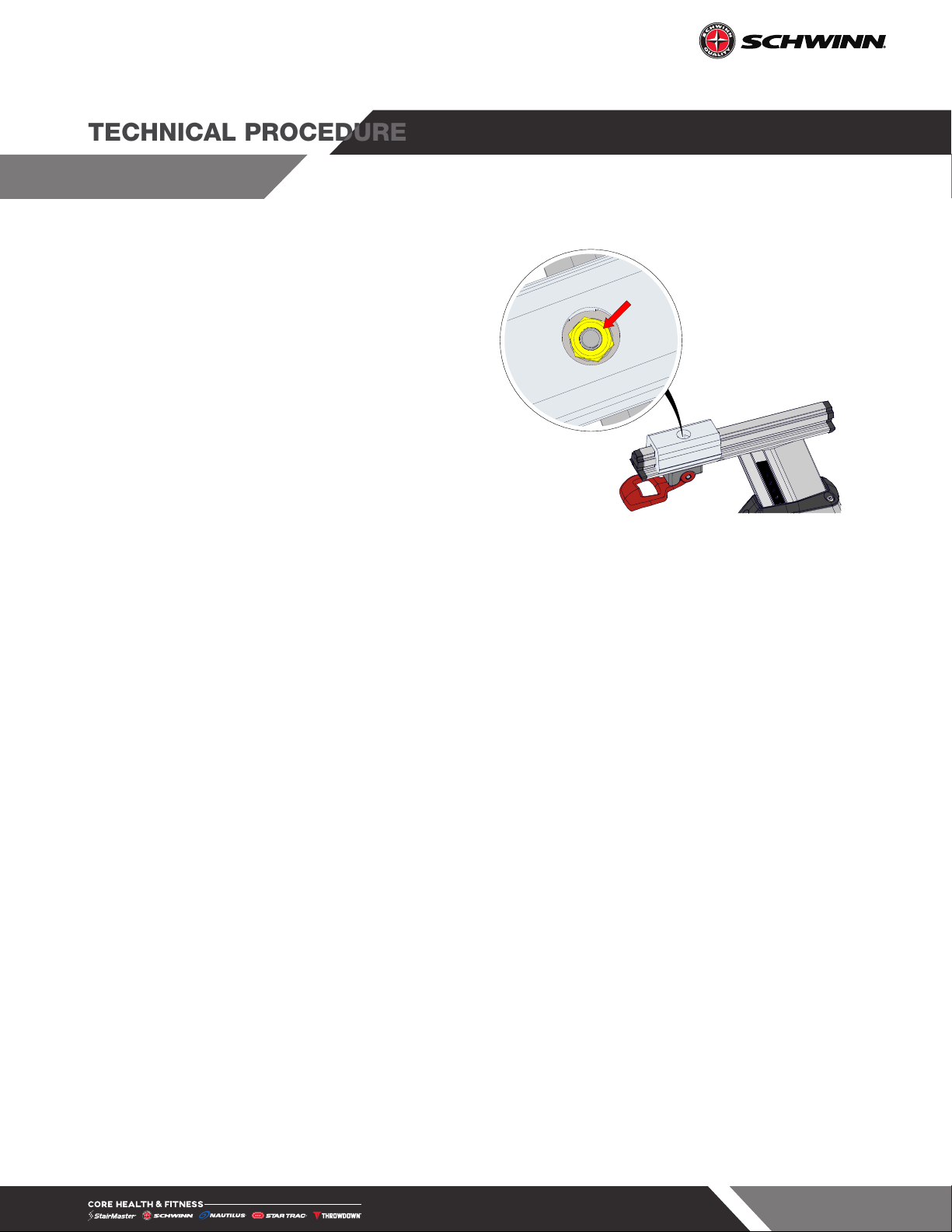
1. Loosen the fore/aft adjustment lever then use
a 5mm allen key to remove the locking screw
from under the seat post.
Notice: When reinstalling the this screw, be sure
to torque to 2 Nm (9 Ft-Lbs).
Fig. 1

Page 3
637-8808 Rev. J
Technical Procedure
2. Slide the seat slider off of the seat post.
Fig. 2
3. Use a ratchet wrench with a 11mm deep
socket to remove the 1/4” nylock nut and
M6 flat washer, then remove the adjustment
lever.
4. Install the new lever using the same hardware
from Step 3.
Notice: If a torque wrench is not available,
please skip to Step 7.
Fig. 3
5. Install 300-0245 “BLOCK, GAUGE, TORQUE,
SEAT, UGC” onto the seat slider so the lever
adjustment nut can be accessed through the
hole int he top of the torque block.
Notice: Step 5 is ONLY valid for bikes PRIOR
to serial number GC7470L22091069 (Schwinn XA),
GC7520L21491157 (Schwinn ZA), GC7510L2213127
(Schwinn ZS), GC7480L22141001 (Schwinn XS).
Fig. 4
Page 4
637-8808 Rev. J
Technical Procedure
6. Ensure that the fore/aft adjustment lever
is closed, then use a torque wrench with a
11mm deep socket to tighten the fore/aft
lever adjustment nut to 4 Nm (2.95 Ft-Lbs).
7. Reinstall the seat slider and locking screw
from Steps 1+2. This will conclude the
procedure - DO NOT CONTINUE TO STEP 7.
8. With the fore/aft adjustment lever open,
tighten the adjustment lever nut 1/4 of a turn,
then close the adjustment lever and check
the function by reinstalling the seat slider
removed in Step 2 and pushing backwards
on the seat slider - it SHOULD NOT move.
9. Repeat Step 7 as needed until the seat slider
is tight. This will conclude the procedure. Fig. 5
Page 5
637-8808 Rev. J
Technical Procedure
Handlebar Slider
1. Flip the fore/aft adjustment lever up.
Fig. 6
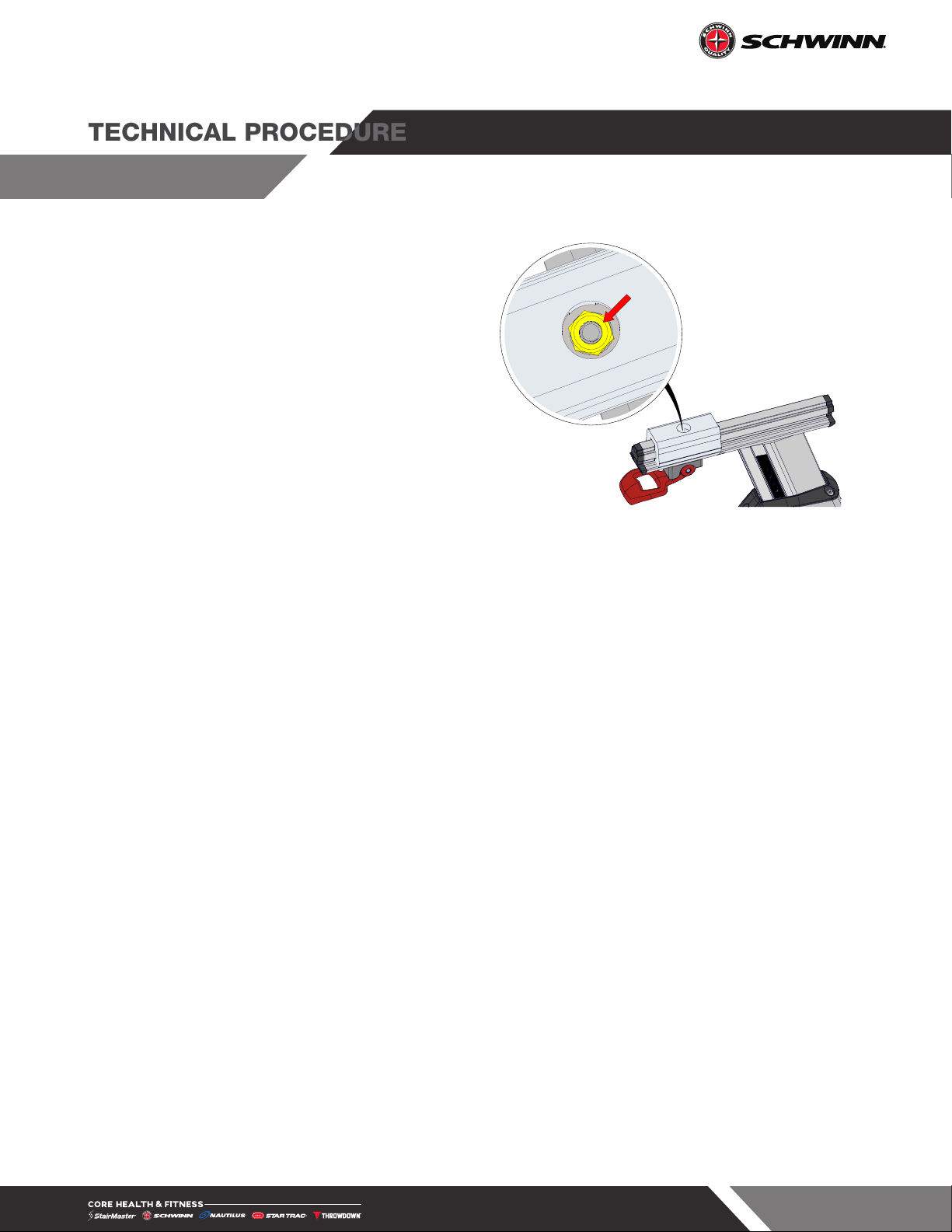
2. Move the handlebars forward until the fore/
aft adjustment lever nut is visible through the
hole on the underside of the handlebar post.
Fig. 7
3. Use a ratchet wrench with a 11mm deep
socket to remove the 1/4” nylock nut and
M6 flat washer, then remove the adjustment
lever.
Fig. 8

Page 6
637-8808 Rev. J
Technical Procedure
NOTE: If a torque wrench is not available, please
skip to Step 4.
4. Close the fore/aft adjustment lever, then use
a torque wrench with a 11mm deep socket
to tighten the fore/aft lever adjustment nut
to 3 Nm (2.21 Ft-Lbs). This will conclude the
procedure.
5. With the fore/aft adjustment lever up, tighten
the adjustment lever nut 1/4 of a turn, then
close the adjustment lever and check the
function by pushing backwards on the
handlebars - they SHOULD NOT move.
6. Repeat Step 4 as needed until the handlebars
are tight. This will conclude the procedure. Fig. 9
Page 7
637-8808 Rev. J
Technical Procedure
Tighten Loose Seat or Handlebars or Seat
Required Tools:
• #2 Phillips Screwdriver
• Torque Wrench
• 10mm Deep Socket
• 3mm Allen Key
NOTE: While the images below show a Schwinn Z cycle, this procedure is also applicable for the Schwinn X
cycle.
Handlebars
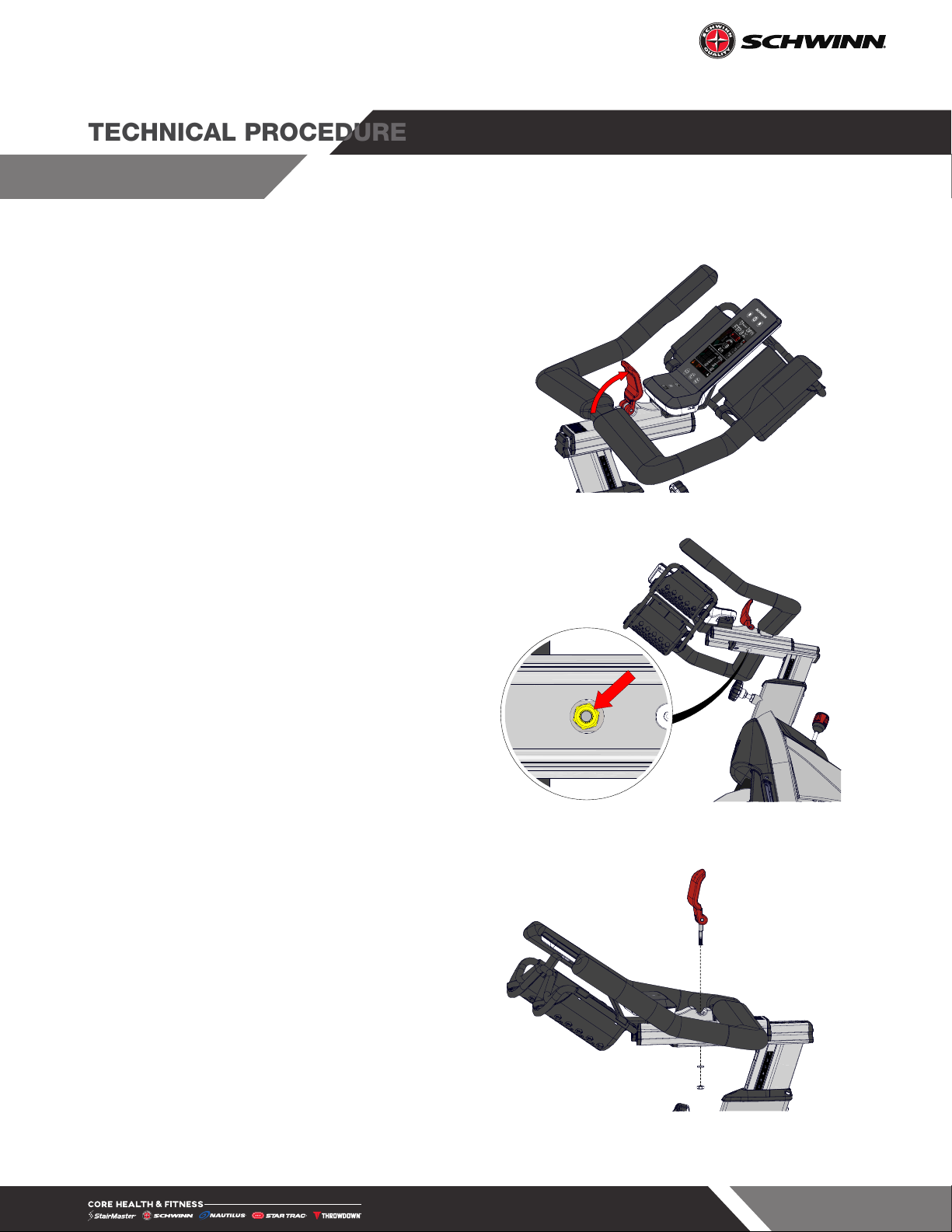
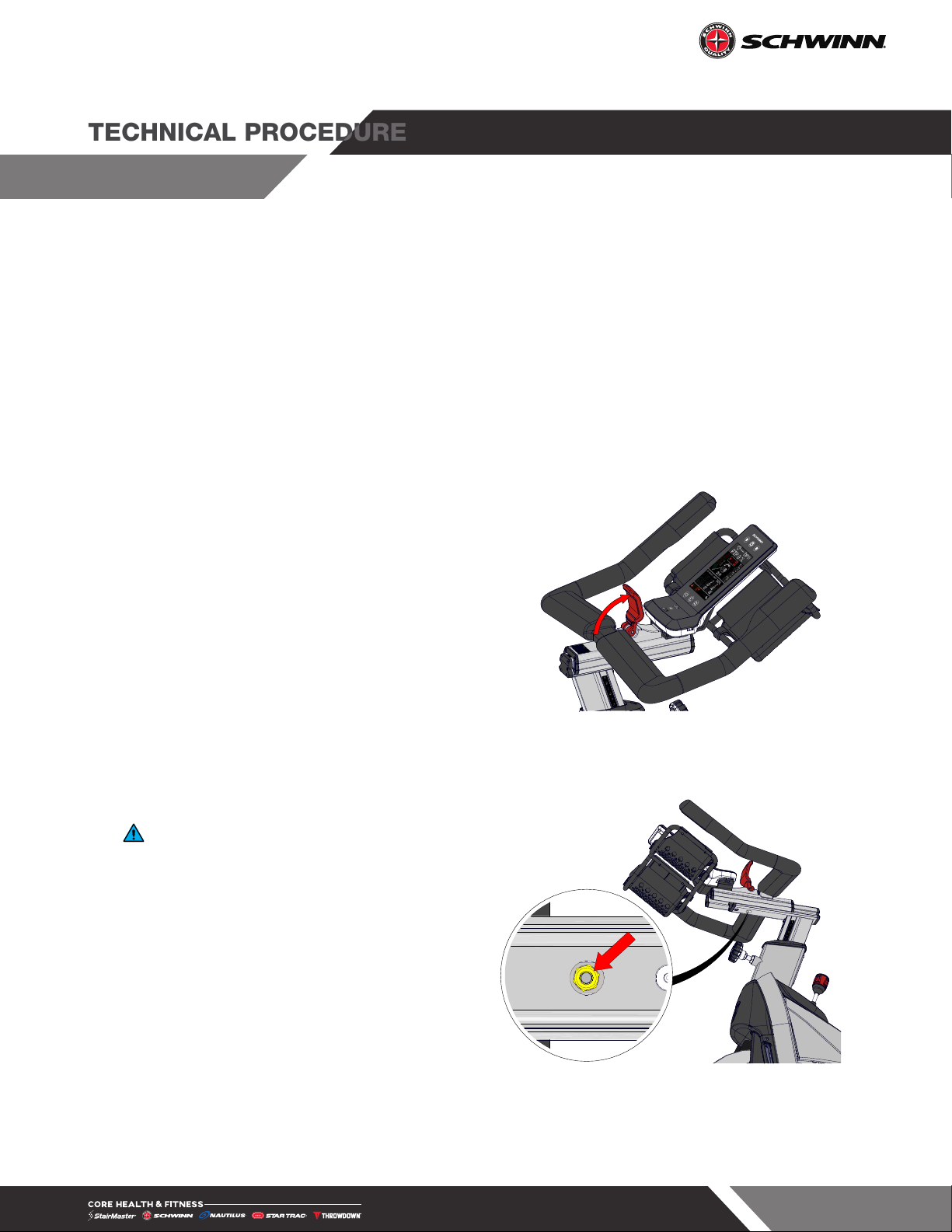
1. Flip the fore/aft adjustment lever up.
Fig. 10
2. Move the handlebars forward until the fore/
aft adjustment lever nut is visible through the
hole on the underside of the handlebar post.
Notice: If a torque wrench is not available,
please skip to Step 4.
3. Close the fore/aft adjustment lever, then use
a torque wrench with a 11mm deep socket
to tighten the fore/aft lever adjustment nut
to 3 Nm (2.21 Ft-Lbs). This will conclude the
procedure.
4. With the fore/aft adjustment lever up, tighten
the adjustment lever nut 1/4 of a turn, then
close the adjustment lever and check the
function by pushing backwards on the
handlebars - they SHOULD NOT move.
5. Repeat Step 4 as needed until the handlebars
are tight. This will conclude the procedure.
Fig. 11
Page 8
637-8808 Rev. J
Technical Procedure
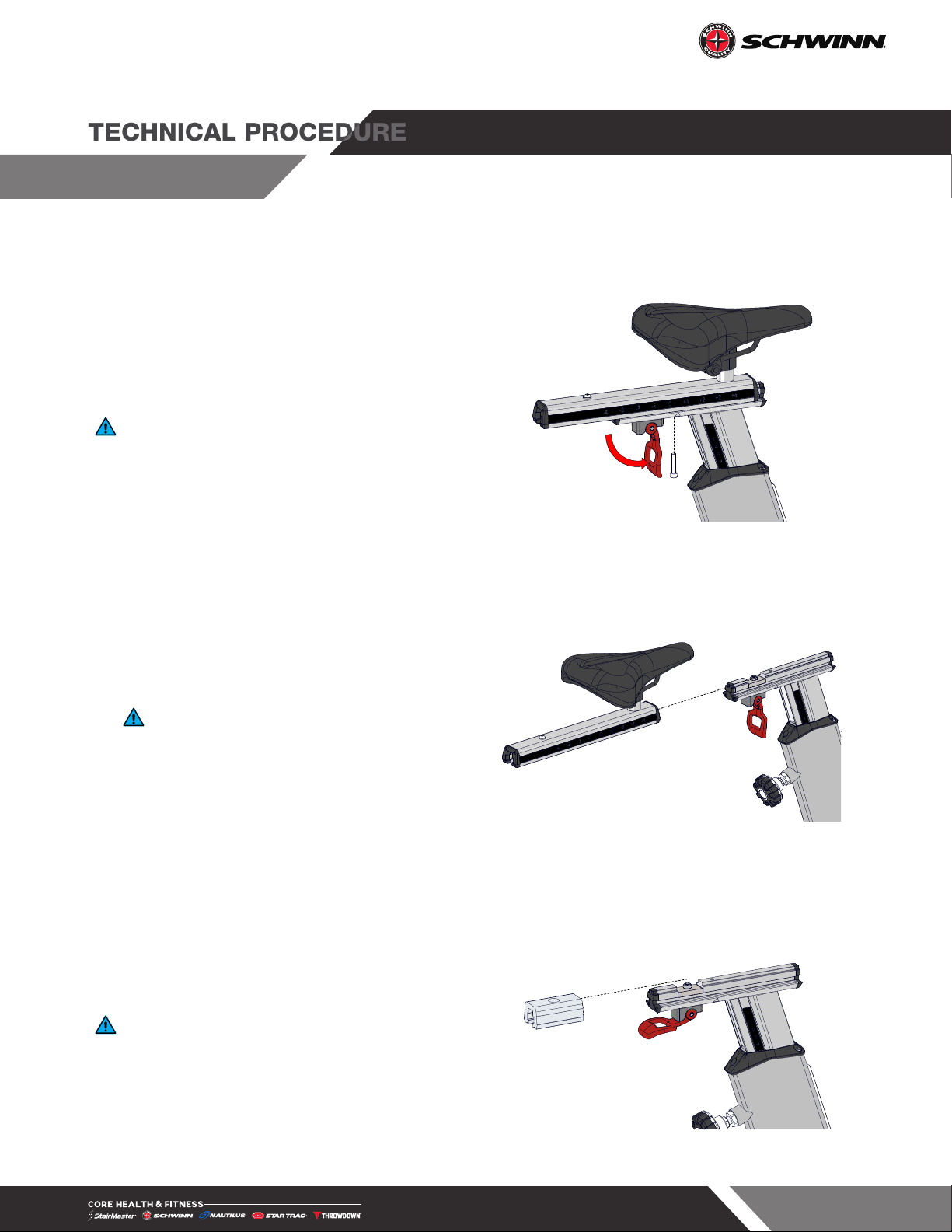
Seat
1. Use a 3mm allen key to remove the socket
head cap screw from the underside of the
seatpost.
Notice: When reinstalling the this screw, be sure
to torque to 2 Nm (9 Ft-Lbs).
Fig. 12
2. Remove the seat slider assembly from the
seat post.
Notice: If a torque wrench is not available,
please skip to Step 5.
Fig. 13
3. Install 300-0245 “BLOCK, GAUGE, TORQUE,
SEAT, UGC” onto the seat slider so the lever
adjustment nut can be accessed through the
hole int he top of the torque block.
Notice: Step 3 is ONLY valid for bikes PRIOR
to serial number GC7470L22091069 (Schwinn XA),
GC7520L21491157 (Schwinn ZA), GC7510L2213127
(Schwinn ZS), GC7480L22141001 (Schwinn XS).
Fig. 14
Page 9
637-8808 Rev. J
Technical Procedure
4. Ensure that the fore/aft adjustment lever
is closed, then use a torque wrench with a
10mm deep socket to tighten the fore/aft
lever adjustment nut to 4 Nm (2.95 Ft-Lbs).
5. Reinstall the seat slider and locking screw
from Steps 1+2. This will conclude the
procedure - DO NOT CONTINUE TO STEP 7.
6. With the fore/aft adjustment lever open,
tighten the adjustment lever nut 1/4 of a turn,
then close the adjustment lever and check
the function by reinstalling the seat slider
removed in Step 2 and pushing backwards
on the seat slider - it SHOULD NOT move.
7. Repeat Step 7 as needed until the seat slider
is tight. This will conclude the procedure. Fig. 15
Page 10
637-8808 Rev. J
Technical Procedure
Cycle Belt and Flywheel Replacement
Required Tools:
• 3mm Allen Key
• 4mm Allen Key
• 6mm Allen Key
• #2 Phillips Head Screwdriver
• 18mm Open-Ended Wrench
• 19mm Open-Ended Wrench x2
• Permanent Marker or Pencil
WARNING: Procedure below involves removal of the flywheel. The flywheel is heavy and two people are
recommended to complete this task. Keep flywheel on blanket or similar to prevent damage.
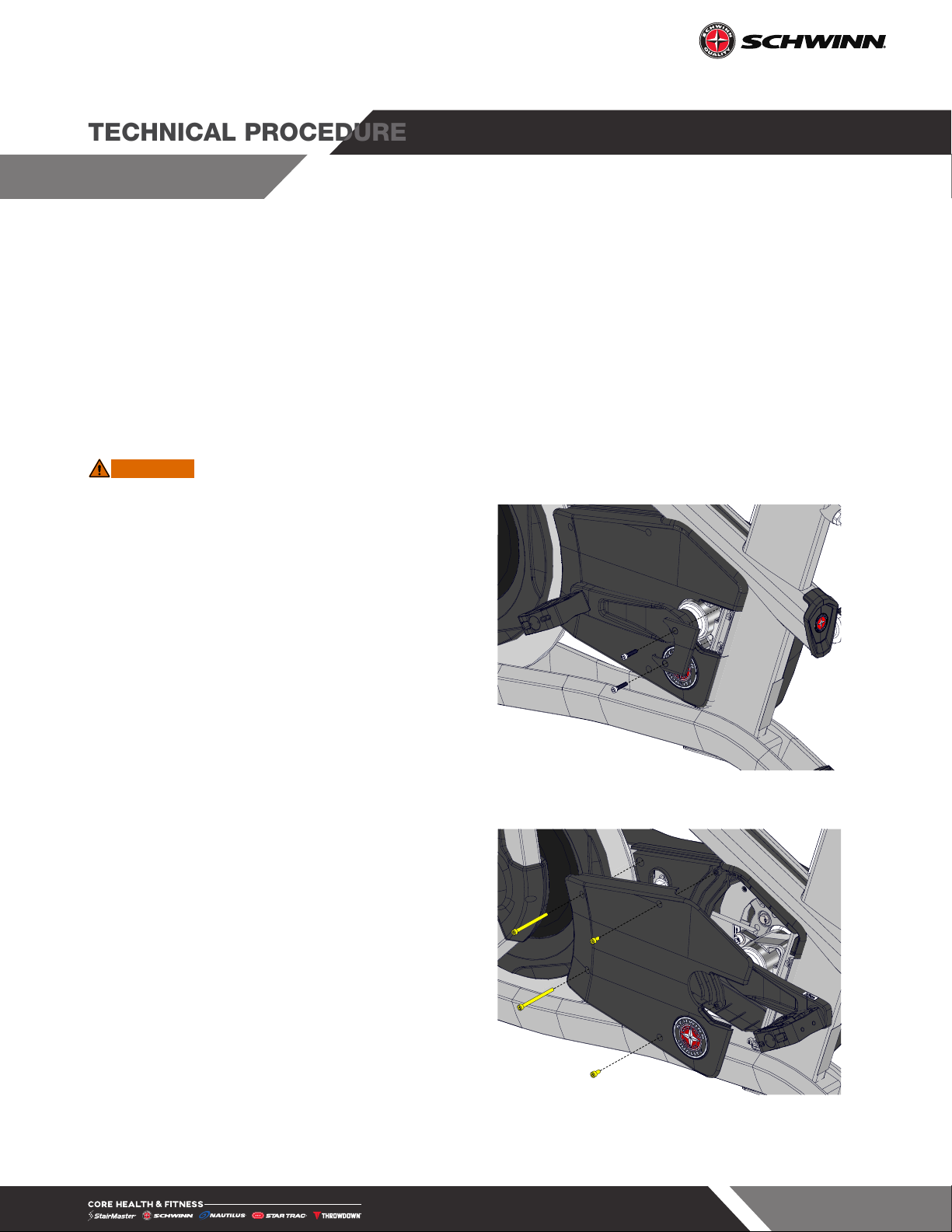
1. Use a 4mm allen key to remove he two (2)
socket head cap screws securing the left side
belt guard cap.
Fig. 16
2. Use a 4mm allen key to remove the four (4)
socket head cap screws securing the left side
belt guard to the bike, then remove the belt
guard.
Fig. 17
This manual suits for next models
1
Table of contents
Other Schwinn Bicycle manuals

Schwinn
Schwinn Roadster User manual

Schwinn
Schwinn HYBRID BICYCLE User manual

Schwinn
Schwinn FASTBACK TRAILER User manual

Schwinn
Schwinn 26" Adult Tricycle User manual

Schwinn
Schwinn S6767 User manual

Schwinn
Schwinn Runabout 13-SC250 User manual

Schwinn
Schwinn Paramount User manual

Schwinn
Schwinn Roadster User manual

Schwinn
Schwinn Classic Cruiser Installation and operating instructions

Schwinn
Schwinn S-14 Cruiser User manual


