Merida ONE 60 User manual
ONE-SIXTY III
ONE-FORTY II
2022-09-09 V 1
1
2
4
5
6
7
8
12
13
15
16
PAGE
We put a lot of effort into the development
of the new ONE-SIXTY/FORTY frame plat-
form to give you the best riding experience
possible. To help you get the most out of
your bike, we have created this setup- and
service guide. It contains all the important
settings and features in an easy-to-
understand format.
INTRODUCTION
SUSPENSION SETUP: FORK
SUSPENSION SETUP: SHOCK
SUSPENSION SETUP NOTES
WHEEL SIZE ADJUSTEMENT
DROPPER SEATPOST
COCKPIT HEIGHT / SERVICE PORT
STORAGE SOLUTIONS / ACCESOIRES
SPARE PARTS
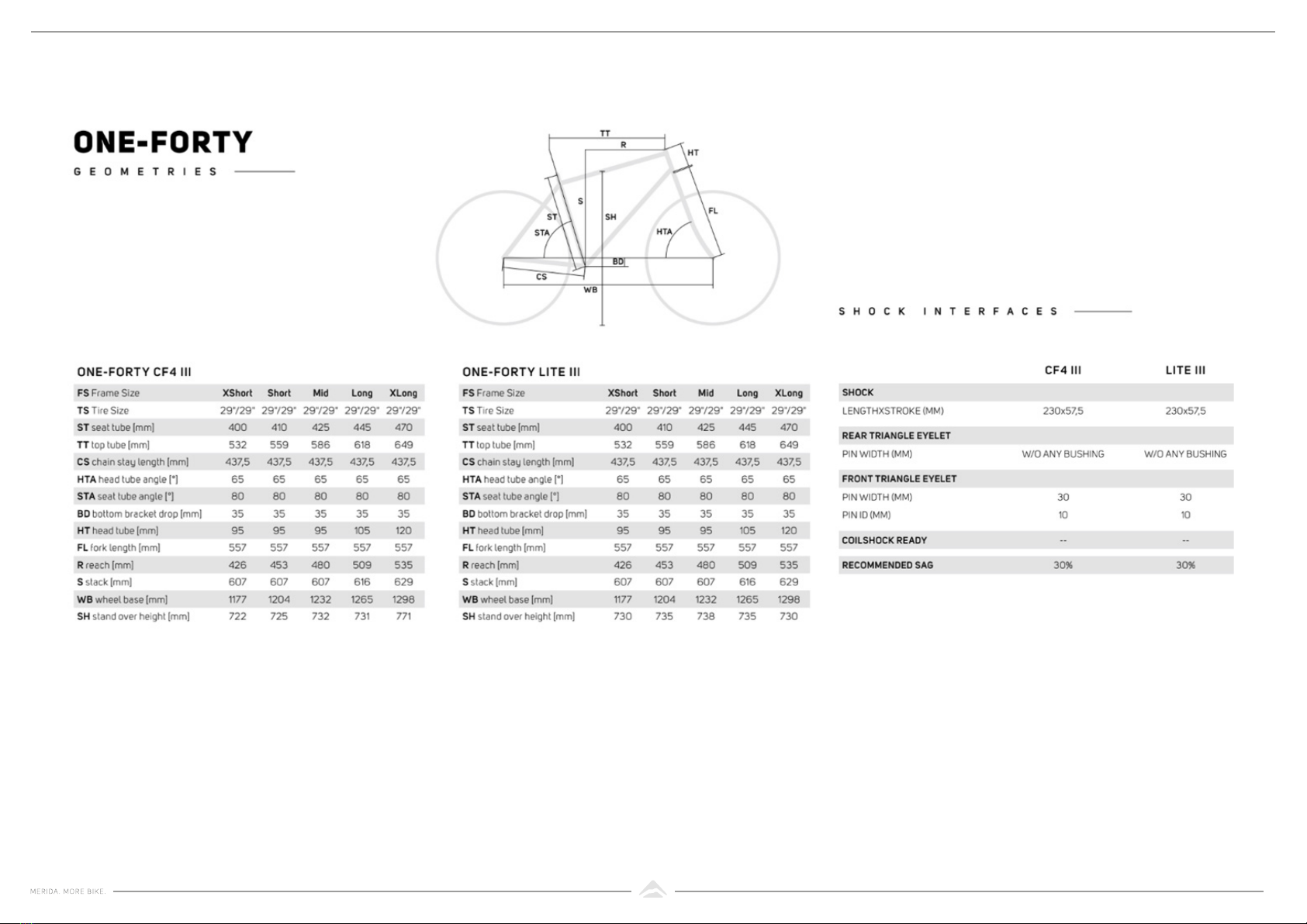
GEOMETRIES
FRAME INTERFACES
EXPLOSION DRAWINGS /
PARTS OVERVIEW
CONTENT

1
All suppliers of suspension forks provide
detailed guides which help you to find your
best set-up. Since they know their products
the best, we want to recommend using
their fork setup guide instead of creating our
own recommendations for the fork.
https://trailhead.
rockshox.com/de/
https://www.ride-
fox.com/ subhome.
php?m=bike#tuning
https://www.srsuntour.
com/en/service/
SUSPENSION FORK ROCK SHOX FOX SUSPENSION SR SUNTOUR
Our team prefers to measure the sag in the
seated riding position. This process is
simple and easier to replicate.
SETTING UP THE SUSPENSION
2
No matter how good the kinematics are,
the suspension will never be at 100%
without the right settings. Therefore, we
offer a recommendation for the ideal shock
setting. The advantage of our described sag
measuring position is that it’s easy to repeat
accurately and consistently..
We recommend 30% sag (negative travel)
with the method of measurement below,
but it is only a reference value. Depending
on your riding style and your preferences,
the sag could differ but 30% is the ideal
starting point.
Too much sag can make the bike feel slug-
gish and unresponsive. Too little sag will
make the bike feel harsh, massively reduce
the rear wheel grip and control.
The following is our way of measuring the
correct sag and all recommendations are
based on this approach. To keep the results
consistent, it is very important to always
follow the same method.
1. Adjust your preferred seat height
2. Turn the compression adjustments (if
available on your shock) to the fully
opened position
3. Sit on the saddle with fully extended
seat post travel. Carry all your clothing
and ride essential you‘d normally take
on a ride. See the picture above.
4. If necessary, hold the front brake, but
not the rear brake
5. Stand up and bounce a little bit on your
bike, then take a seat again
6. Push back the O-rings on the shock
7. Step down from the bike carefully. Avoid
moving the position of the O-ring!
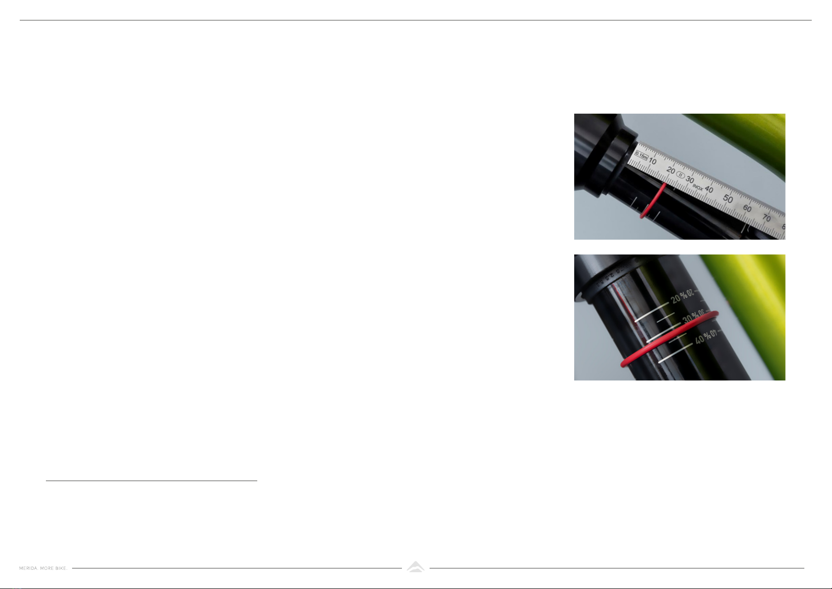
8. Measure the distance from the dust seal
to the O-ring:
9. If necessary, adjust your air pressure to
achieve the above values.
After each change of shock pressure,
slowly compress the shock by pushing the
saddle to equalize the pressure between
the positive and negative air chamber. You
can hear the equalization by the noise of air
whistling. Mostly it’s found at the sag point.
Model
ONE-SIXTY
ONE-FORTY
Shock
stroke
65 mm
57,5 mm
Sag (30% of
shock stroke
19.5 mm
17.3 mm
REAR SHOCK
30% SAG VALUES
RECOMMENDED METHOD OF
SAG MEASURMENT WITH AIR
SHOCKS

3
The ONE-SIXTY and ONE-FORTY models
are specified mainly with shocks from the
RockShox Super Deluxe series. Therefore
we recommend the following air pressure
figures as a first starting point.
If you want to use the ONE-SIXTY with
coil shocks, we recommend the following
spring rates for the shocks.
The ONE-SIXTY models are specified
mainly with shocks from the RockShox
Super Deluxe series. The rebound damping
is directly related to the air spring pressure
and needs to be adjusted after setting the
air pressure. Therefore we recommend the
following settings as a first starting point.
Rider weight
(including all
essentials)
Rider weight
(including all
essentials) LS rebound
(clicks from
fully closed)
Air pressure rear shock
RockShox Super Deluxe
ONE-SIXTY
Coil spring rate Air pressure
ONE-SIXTY ONE-FORTY
120 psi
140 psi
160 psi
180 psi
200 psi
225 psi
250 psi
300 Ibs
350 Ibs
400 Ibs
450 Ibs
500 Ibs
120 psi
140 psi
160 psi
180 psi
200 psi
220 psi
240 psi
260 psi
280 psi
50 kg
60 kg
70 kg
80 kg
90 kg
100 kg
110 kg
55 - 65 kg
65 -75 kg
75 - 85 kg
85 - 95 kg
95 -105 kg
12 (fully open)
11
9
8
6
5
3
1
0
145 psi
165 psi
185 psi
205 psi
225 psi
250 psi
275 psi
RECOMMENDED AIR
PRESSURES FOR ROCK SHOX
SUPER DELUXE SHOCKS
RECOMMENDED COIL
SRPING RATES FOR
COIL SHOCKS
REBOUND DAMPING

4
Experimenting with the suspension can be
fun! But modify only one variable and note
the settings accurately. Always count the
compression and rebound tunes from fully
closed position.
Please note: Not all suspension parts have
High-Speed and Low-Speed adjusters.
1
2
3
4
5
6
7
8
9
10
Setup Nr Pressure Compression Fork Rebound Fork
High
Speed
High
Speed
High
Speed
High
Speed
Fork
Low
Speed
Low
Speed
Low
Speed
Low
Speed X / 10
Compression Shock Rebound Shock Feeling
psi
psi
psi
psi
psi
psi
psi
psi
psi
psi
psi
psi
psi
psi
psi
psi
psi
psi
psi
psi
clicks
clicks
clicks
clicks
clicks
clicks
clicks
clicks
clicks
clicks
clicks
clicks
clicks
clicks
clicks
clicks
clicks
clicks
clicks
clicks
clicks
clicks
clicks
clicks
clicks
clicks
clicks
clicks
clicks
clicks
clicks
clicks
clicks
clicks
clicks
clicks
clicks
clicks
clicks
clicks
clicks
clicks
clicks
clicks
clicks
clicks
clicks
clicks
clicks
clicks
clicks
clicks
clicks
clicks
clicks
clicks
clicks
clicks
clicks
clicks
clicks
clicks
clicks
clicks
clicks
clicks
clicks
clicks
clicks
clicks
clicks
clicks
clicks
clicks
clicks
clicks
clicks
clicks
clicks
clicks
/ 10
/ 10
/ 10
/ 10
/ 10
/ 10
/ 10
/ 10
/10
/10
NOTES FOR YOUR
SUSPENSION SETTING
Pressure
Shock

5
1. Remove the rear wheel with the axle
lever
2. Disassemble the shock with 6 mm and
4 mm Allen keys
3. Loosen the outer bolts of the seatstay (A)
four turns. Tap those screw head lightly
with a hammer to ensure the flipchip (B)
loosens from its conical seat. Unscrew
the bolts afterwards completely.
1. Slightly compress the rear triangle to
get access to the flipchip. Remove and
twist both flip chips inside the rocker.
The line on the flipchip must be aligned
with the line of the desired wheel size
on the rocker.
We know that both rear wheel sizes (27.5”
for mullet and 29”) have pros and cons.
Therefore, we have taken into both rear
wheel sizes into account and allow a simple
change that leaves the important geometry
data such as reach, stack and the angles
untouched.
29” wheels are faster, have a better rollover
behaviour and are ideal for larger people
and for the wide range of usage. But thanks
to the 27.5“ rear wheel and corresponding
4mm shorter chainstay length, the mullet
set-up with the 27.5” rear wheel rides more
playfully and forgives more mistakes. The
greater bum clearance will especially suit
small riders on steep terrain.
4.
5. Assemble the screws (A) again. Be sure
to mount the washers in between.
Tighten the screws (A) with its imprinted
torque by using a torque wrench.
6. Mount the shock again with its imprinted
torque by using a torque wrench.
Please note that your tyre pressure has
also a massive impact on your riding.
Go and check the SRAM tyre pressure
guide:
https://axs.sram.com/guides/tire/pressure
WHEEL SIZE
ADJUSTEMENT
CHANGE THE REAR
WHEEL SIZE
A
A
B
B

6
1. Loosen screw (B) with a 2.5 mm Allen
key and open the flap A to the side.
2.
3.
4.
5.
6.
7.
8.
9.
10.
11.
12.
13.
14.
15.
16. Using an Allen key (2.5mm), turn the
screw (C) to the left (-) until the orange
rope stops moving. This can be obser-
ved through the viewing window
17. Close flap (A) and tighten screw B with
a 2.5 mm Allen key.
1. Loosen screw B with a 2.5 mm Allen
key and open the flap (A) to the side.
2. Press the remote lever to open the
valve, the seatpost will extend to its full
travel.
3. Close flap (A) and tighten screw (B) with
a 2.5 mm Allen key.
On the carbon frames you have the possibi-
lity to mount an Eightpins seatpost.
Eightpins Online Shop:
https://www.eightpins.com/prodkat/
komplettstuetze/
1. Press the remote lever to open the valve
and lower the seat post with the rider‘s
weight to the desired maximum exten-
sion position.
MERIDA TEAM TR DROPPER
SEATPOST ADJUSTMENT
EIGHTPINS SEATPOST
MAXIMUM TRAVEL LIMITATION
USAGE OF COMPLETE TRAVEL
2.
3.
4.
B
A
C
7
EAN: TBA
EAN: TBA
EAN: TBA
EAN: TBA
EAN: TBA
EAN: TBA
You may have noticed that this bike has a
relatively short head tube on all sizes. This
is part of our concept, because for smaller ri-
ders it’s often very complicated to lower your
cockpit height, but it’s easy to raise it up.
With 5 & 10mm ahead spacers and
different riser bars is possible to increase to
cockpit height to your preferred height.
Sometimes regular maintenance is not
enough and you need new bearing kit or a
completely new headset. Just search for
your model in the ACROS headset finder:
https://acros-components.com/en/replace-
ment-headsets
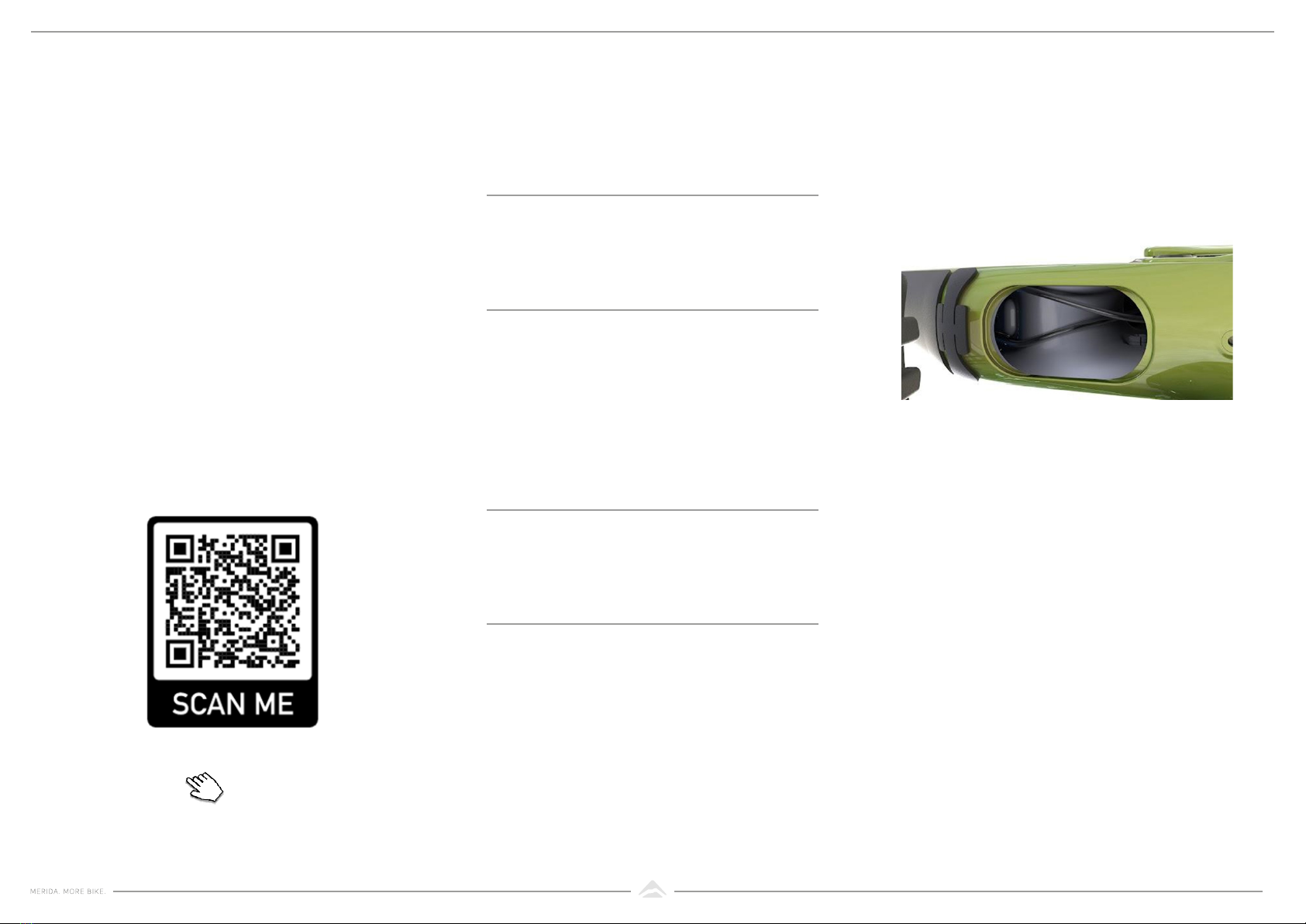
To ensure hassle free cable routing, we have
built a service port into the frame.
You have easy access to the cable-carry-
ing liners in the downtube as well as to the
cable of the dropper seatpost. For easy cable
routing start pushing the cable housing from
the back of the rear triangle to the service
port through the cable-carrying liner up to
the headtube.
COCKPIT HEIGHT MERIDA COCKPIT PARTS SERVICE PORT
40 mm
50 mm
EAN: 4057094026863
EAN: 4057094026870
MERIDA EXPERT handle bar
MERIDA EXPERT eTRII stem
MERIDA ahead spacers
MERIDA anti-rotation spacer
15 mm rise, 780 mm wide
aluminium
30 mm rise, 780 mm wide
carbon
45 mm rise, 780 mm wide
carbon
5 mm height
10 mm height
3 mm height

8
We discovered that we can store some
small things in the frame, after we enlar-
ged the service port opening a little bit. We
made a bag so you not lose anything in the
frame.
We put some small parts into the bag, like a
small pump, a spare UDH hanger, a tube-
less tyre puncture repair kit, a spare chain
quick link, some inner tube patches, a CO2
cartridge. It’s up to you, as long as the pa-
ckage isn’t too bulky. You could even think
about a spare inner tube when folded flat.
USING STORAGE SOLUTIONS
AND ACCESSORIES
MERIDA ESSENTIAL TOOL BAG
EAN: TBA
ONE-SIXTY / ONE-FORTY essential tool bag
9
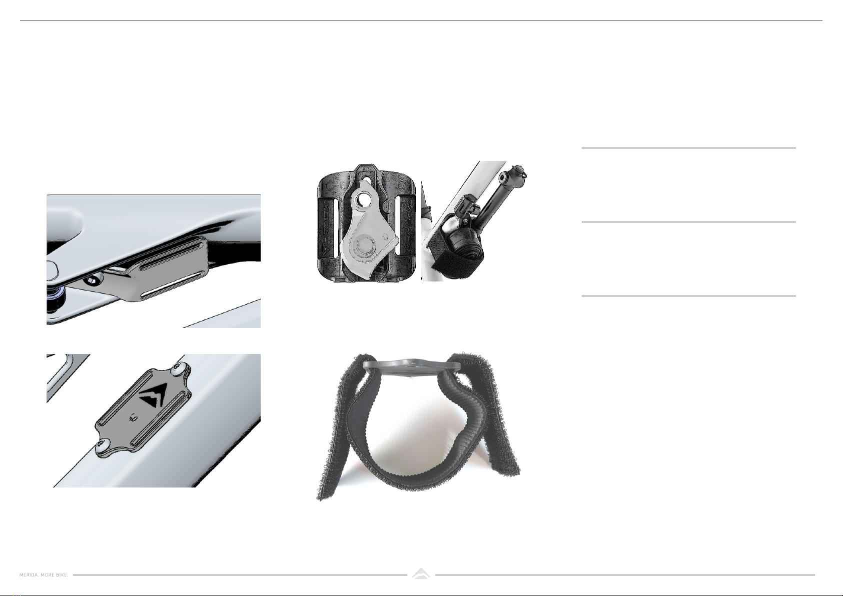
For all tube mounts we recommend to wrap
the strap like the following:
Depending on your frame you have several
possibilities to mount a tube or some other
accessories. On the ONE-SIXTY and ONE-
FORTY frame the tube base mount is located
at the front shock mount.
But you can also mount the Merida Trail
Mount, which can carry a spare UDH han-
ger, two 16g CO2 cartridges or a pump and
also a tube on top of it.
TUBE / TRAIL MOUNT
EAN: 4057094030136
EAN: 4057094030112
MERIDA TUBE / TRAIL
MOUNT PARTS
40 mm & 64 mm
bottle cage
carbon frame
carbon frame
EAN: TBA
MERIDA TRAILMOUNT w. Strap
MERIDA tube mount standard w. strap
MERIDA TRAILMOUNT compatible pump
40 mm & 64 mm
bottle cage

10
With our MERIDA TR rear axle lever, the rear
axle can be tightened. But the lever works
also as a 6mm and 4mm Allen key, with
which further parts like the stem and seat
clamp can be tightened on the ride.
To use the removable axle lever, just pull
the lever out on the non-drivetrain side of
the bike. To restore it, simply press it back in
again.
All ONE-SIXTY and ONE-FORTY models
include a tool box and multitool below the
saddle. The V-MOUNT enables mounting
the tool box and mini tool.
The multitool includes the following tools:
o Allen key: 2/2,5/3/4/5/6/8 mm
o Screw driver: +/-
o Torx: T10/T25/T30
To use the multitool, open the flap on the
tool box and pull it out. To restore it, just
press it in again and close the flap.
To remove the whole box from the saddle,
remove the tool out of the box and disas-
semble the flap from the box by pulling it
out. Unscrew the box from the V-MOUNT by
using a 3mm allen key.
REMOVABLE AXLE LEVER V-MOUNT WITH INCLUDED
MULTI TOOL
EAN: 4057094024029
EAN: 4057094020809
EAN: 4057094020793
with 6 mm / 4 mm
allen key
12-in-1
for installation below
the saddle
MERIDA removable axle lever
MERIDA Mini Tool
Mini Tool V-Mount Box

11
The ONE-SIXTY/ONE-FORTY is equipped
with two fender options. The short mudguard
protects the shock, seat tube and bearings
from dirt and stone chips. We recommend
that you always leave the short fender
mounted therefore we have integrated this
into the design concept. Additionally it has
the function to hold the chainstay protector
in place.
But so you are ready for the really muddy
trails, there is the option of an additional long
fender. This complements the short fender
and offers significantly more protection
against mud and water..
1. Remove the rear wheel
2. Attach long fender to the seat stays.
3. Put the long screws (A) through the seat
stay bridge of the frame and tighten
them to 4 Nm.
4.
5.
6.
7.
8.
9.
10.
11.
12.
13.
14.
15.
16.
17.
18.
19. Tighten the shorts screws (B) on the
inside of the seat stays with max. 2 Nm.
We recommend the use of some
medium strength thread-locking fluid.
20. Reinstall the rear wheel and double
check that there is enough clearance for
contact-free rotation.
INSTALLING THE DIFFERENT
FENDERS
MOUNTING THE LONG FENDER
EAN: TBAfor ONE-SIXTY /
ONE-FORTY
Long Fender
4.
5.
A
B

12
The SRAM derailleur hanger, which is used
across many bike brands, offers the great
advantage that the derailleur hanger is
available everywhere and easily. In the
event of a failure, you have an immediate
replacement!
The carbon frames have a recess for the
integrated FIDLOCK mount to have a flush
side view and they come as stock with the
integrated magnetic base. Aluminium mo-
dels can use the standard base.
If you don’t want to use the integrated base
it’s possible to mount a standard bottle
cage. Some cages will not fit properly in the
recess, so we have made a cover plate to
space them up.
A bottle comes with the twist bottle
connector, but can be purchased without the
connector as well.
SRAM UNIVERSAL DERAILLEUR
HANGER (UDH)
FIDLOCK MAGNETIC BOTTLE
EAN: 710845840135SRAM part number:
00.7918.089.000
SRAM UDH
SPARE PARTS
EAN: TBA
EAN: TBA
EAN: TBA
EAN: TBA
EAN: TBA
EAN: TBA
EAN: TBA
MERIDA FIDLOCK bottle, transparent
MERIDA FIDLOCK bottle, matt black
MERIDA FIDLOCK bottle, transparent
MERIDA FIDLOCK bottle, matt black
MERIDA FIDLOCK bottle, matt black
MERIDA cover plate for FIDLOCK „base up“
0.6 l, with connector and
standard base
0.6 l, with connector
0.6 l, with connector
0.6 l
0.6 l
Fidlock part number:
F9617-000102(BLK)
MERIDA FIDLOCK bottle, matt black
0.6 l, with connector and
standard base

13
14

15
FRAME INTERFACES

16
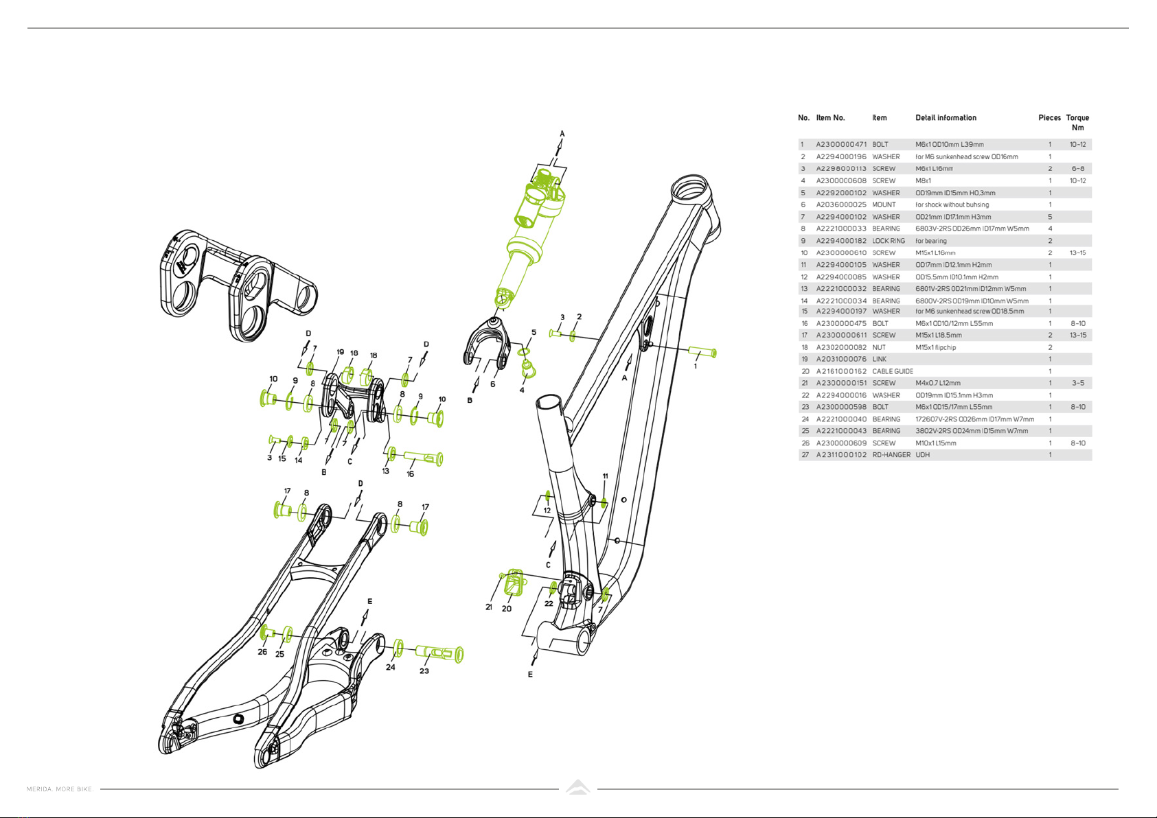
CARBON FRAME
EXPLODED VIEW
Item No can be purchased through
your local MERIDA dealer.
17
ALUMINIUM FRAME
SUSPENSION HARDWARE
Item No can be purchased through
your local MERIDA dealer.

18
ALUMINIUM FRAME
SMALL PARTS
Item No can be purchased through
your local MERIDA dealer.
Other manuals for ONE 60
1
This manual suits for next models
1
Table of contents
Other Merida Bicycle manuals


