Meridian 2300M Series User manual

14 Jacaranda Court
BEECHMONT QLD 4211, Australia
Phone: +61-(0)7-3103-0750
Fax: +61-(0)7-5604-1402
E-mail: sales@teletechnique.com
Web: www.teletechnique.com
ABN 34 383 278 861
Teletechnique is registered in the State of Queensland Australia as business number BN 21 956 534
1 August 2011
To whom it may concern
MERIDIAN TECHNOLOGIES INC PRODUCTS IN AUSTRALIA
Messrs Meridian Technologies Inc of Elmont NY, United States of America, design
and manufacture at their headquarters in Elmont (near New York) an extensive
range of quality equipment for use in fibre optic networks for broadcasting, CCTV,
and industrial automation.
Teletechnique is proudly representing Meridian Technologies Inc in Australia and
supports the products with local expertise.
For product information and requests for quote, please call 07 3103 0750.
Yours faithfully
Ger Vloothuis
General Manager

NetworkDiagnostics-LocalandRemoteAccess
SurfaceMountTechnology(SMT) forHighReliabilityandRepeatability
FaultTolerantSelf-HealingRingorLinearBusTopology
Multiple-MasterCapability
2x16CharacterLCDDisplayoneachModem
AsynchronousDataRatesupto125KbpsNRZ
UsesDigitalFPGATechnology
DataProtocolIndependent
RS-232D,RS-422,RS-485(2and4wire)andTTL
TrueTri-StateSensing(notimeoutsneeded)
SingleHandshake–RS-232D(RTS&CTS)
or2Channel125KbpsDataMultiplexer
FullHandshakingAvailable–RS-232D
DataRe-clocked&RegeneratedateachModem
99NodeCapability
IndividuallyAddressableModems
Anti-streaming(on/offorvariabletime)
LocalandRemoteLoopBackTest
LocalDryContactAlarm (N.O.)
BuiltInDualInputPowerRedundancy
AlarmedBatteryBackup
Dual Input: 12 VDC - 35 VDC, 9 VAC - 24 VAC
HotSwappableInputPower
FullyCompatiblewithSpectraSmart™PCBasedNetworkManagement
Build In BER Tester w/GUI
ESDInputProtection
ExceedsNEMATS-1/TS-2andCaltransSpecifications
FEATURES:
•
•
•
•
•
•
•
•
•
•
•
DESCRIPTION:
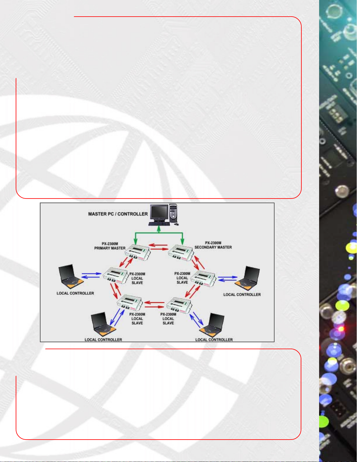
The2300Misastateoftheartselfhealing,counterrotatingmulti-dropdata
modemdesignedtoprovidetheuserwithtroublefreedatatransmissionin
bothringandstringconfigurations.Inadditiontobeingequippedwithallofthe
expectedfeatures, localandremotediagnosticcapabilitiesareincludedin
eachmodem.Theuser-friendlydiagnosticsmenucanbeaccessedviatwo
smallbuttonslocatedonthefrontpanel.Thesebuttonsareusedforscrolling
throughthe menufunctions.Thestatusofanyothermodemcanbeviewed
on the SpectraSmartTM System. Field technicians can perform local and
remotediagnostics without theaid of aPC. Parameters viewableon the
LCDdisplayareinternalmodemtemperature,powersupplyvoltages,opti-
calringstatus,locationoffiberbreaks,unitfailures andmanyothercritical
parameters.Ifaparameterisexceeded,aflashinglightandaudiblealarm
areactivatedatallmodems.Bothprimaryandsecondaryringsaremoni-
toredsimultaneouslybythenetworkdiagnostics.Iftheprimaryringisbro-
ken,the LCD will display theaddressofthemodemsoneachsideof the
breakprovidingquicktroublefree identification.Intheeventofafault,cus-
tomer data will automatically be transferred to the secondary ring.
SpectraSmartTM PC,awindowsbasedGUIdriven network management
system can be connected to the Master Primary and Master secondary
modemsviaanRS-232orRS-485cable.WhenaPCisused,theGUIwill
displaytheentireNetworkandachangeofcoloratthetroublelocation.The
SpectraSmartTM softwareworksinconjunctionwiththeLCDdisplaylocated
ontheindividualmodems. When operating normallythe PrimaryMaster
modemmonitorsquantityandnumericalsequenceofslavemodemsonthe
ringandeachmodemstoresthelastfivealarms,whichcanbedisplayedon
thelocalLCDdisplay.The2300Mfamilycombinessophisticatedself-heal-
ingringtopologyandcomputerbasedlocalandremotediagnosticstopro-
vide your network with round the clock monitoring. The self-healing ring
immediatelydetectsfaultsandreroutescommunicationstokeepyournet-
workoperationalwhilethebuiltindiagnosticsreducesthetimerequiredby
technicianstoanalyze,locateandrepairthefault.
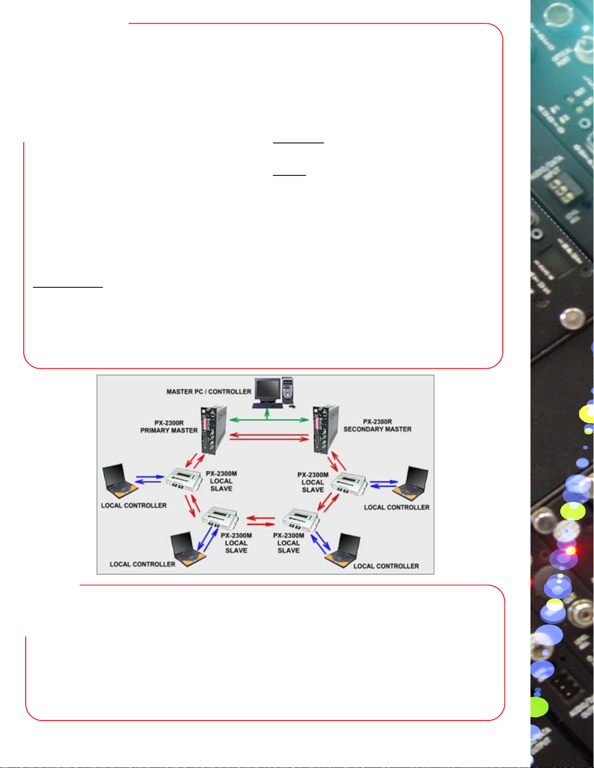
CONFIGURATIONS:
Themodemscanbeinstalledasastringorcounterrotatingfaulttolerant
rings.TheswitchselectablefeatureallowseachmodemtobesetasaMas-
terPrimary,MasterSecondaryoraSlave.TheMasterPrimaryandMaster
Secondary modems are connected to the PC by an RS-232 or RS-485
cableandprovideredundancyifMasterPrimaryortheopticalringisbro-
ken.
APPLICATIONS:
DataMultidropSelf-Healing
OpticalRingModem
SERIES2300M
CardAccessControl
SecurityTelemetrySystems
SCADA System
ComputerNetworks
ProcessControlSystems
ITS
•
•
•
•
•
•
•
•
•
•
•
•
•
•
•
DATA
DATA
DATA
DATA
DATA
DATA
DATA
DATA

SPECIFICATIONS:
Quality
MTBF. . . . . . . . . . . . . . . . . .
. . . . . . . . . . . . . . . . . . . . . . . >260,000 hours @ Ground Fix
35oC per MIL217F
Connectors
Optical . . . . . . . . . . . . . . . . .
Power . . . . . . . . . . . . . . . . . .
I/O Data. . . . . . . . . . . . . . . . .
(4) STTM, FC, SC
Dual 2 Pin Terminal Blocks
DB25 Female
* Measured @ 1Km (multimode), 10 Km (singlemode)
** Add 30mm to include mounting flanges
MeridianTechnologies Inc.
Visit our web side: www.meridian-tech.com or www.meridian-tech.tv
OPTICAL:
Power
Operating. . . . . . . . . . . . . . . .
. . . . . . . . . . . . . . . . . . . . . . . .
. . . . . . . . . . . . . . . . . . . . . . . .
Inputs. . . . . . . . . . . . . . . . . . .
500mA@ 12 VDC
300 mA@ 24 VAC
(Alarmed)
Dual
* Distance is limited to fiber loss and splices
** Higher output lasers available
Fiber Type/Size
(um)
Multimode* (SLED)
62.5/125
62.5/125
Singlemode(Laser)
9/125
9/125
Optical Output
(dBm)
-15
-16
-3**
-3**
RecieverSensitivity
(dBm)
-30
-30
-33
-33
Optical Budget
(dB)
15
14
30
30
Wavelength
(nm)
850
1300
1310
1550
Optical
Connector
ST,SC
ST,SC
ST,FC
ST,FC
OpticalDynamic
Range (dB)
30
30
30
30
Data
Formats. . . . . . . . . . . . . . . . . . . .
. . . . . . . . . . . . . . . . . . . . . . . . . .
. . . . . . . . . . . . . . . . . . . . . . . . . .
. . . . . . . . . . . . . . . . . . . . . . . . . .
Rate. . . . . . . . . . . . . . . . . . . . . . .
Bit Error Rate. . . . . . . . . . . . . . .
PWD (Pulse Width Distortion)
.
RS-232D, RS-422A,
RS-485 2w/4w, TTL,
SingleHandshake - RS-232
(Full HandshakingAvailable)
DC to 125 Kb/s (Async.)
10-9 *
<10% @ max. Data Rate Physical
Dimensions:
PX-2300M** . . . . . . . . . . . .
. . . . . . . . . . . . . . . . . . . . . . . . 152 mm (6”)L, 47 mm (1.8”)W
97 mm (3.8”)H
Enviromental
Operating Temperature. . . . .
Storage Temperature. . . . . . .
Relative Humidity. . . . . . . . .
-40oC to +74oC
-55oC to +85oC
0 to 95% Non-condensing
Indicators & LED
LCD Display. . . . . . . . . . . . .
LED Display (12). . . . . . . . .
. . . . . . . . . . . . . . . . . . . . . . . .
. . . . . . . . . . . . . . . . . . . . . . . .
. . . . . . . . . . . . . . . . . . . . . . . .
. . . . . . . . . . . . . . . . . . . . . . . .
2x16 Character Display
Alarm, Power A, Power B,
Master, Link A, Link B,
DiagnosticA, Diagnostic B,
Data TX, Data RX,
Handshake TX, Handshake RX

Data Multidrop String, Self-Healing
Optical Ring Modem, Rack Mount
SERIES 2300R
DATA
DATA
DATA
DATA
DATA
DATA
DATA
DATA
Network Diagnostics - Local and Remote Access
Surface Mount Technology (SMT) for High Reliability
and Repeatability
Fault Tolerant Self-Healing Ring or Linear Bus
Topology
Multiple-Master Capability
Asynchronous Data Rates up to 125 Kbps NRZ
Uses Digital FPGA Technology
Data Protocol Independent
RS-232D, RS-422, RS-485 (2 and 4 wire) and TTL
True Tri-State Sensing (no time outs needed)
Single Handshake – RS-232D (RTS & CTS)
or 2 Channel 125 Kbps Data Multiplexer
Data Re-clocked & Regenerated at each Modem
99 Node Capability
Individually Addressable Modems
Anti-streaming (on/off or variable time)
Local and Remote Loop Back Test
Local Dry ContactAlarm (N.O.)
Hot Swappable Input Power
Fully Compatible with SpectraSmart™ PC Based
Network Management
Built In BER Tester w/GUI
ESD Input Protection
Exceeds NEMA TS-1/TS-2 and Caltrans
Specifications
FEATURES: DESCRIPTION:
CONFIGURATIONS:
MARKETS:
ITS
Card Access Control
Security Telemetry Systems
SCADA System
The 2300R is a state-of-the-art, rack mount, multi-drop data mo-
dem designed to provide the user with trouble-free data transmis-
sion in both self-healing ring and Multidrop string configurations.
This 2-slot card modem has self-diagnostic capabilities that can
be monitored on a computer via the front-panel mounted RS-232
or USB ports. A front panel mounted RS-485 port is provided for
interconnecting the network diagnostics on two or more master
modems. The PC based Network Management system incorpo-
rates real time system diagnostics for monitoring various net-
work and modem parameters including, but not limited to: Optical
connectivity, Optical budgets, Power supply voltages, Individual
modem operating parameters, alarms & alarm history and network
BER. A GUI network representation monitors the fiber connectiv-
ity for other modems that are on the ring / string network. If a fiber
is broken an alarm activates, giving the user a visual representa-
tion of a broken fiber and its location in the network. Both primary
and redundant fiber rings are simultaneously monitored by the
network diagnostics. The 2300R product family combines so-
phisticated self-healing ring topology and computer based diag-
nostics to provide your network with round the clock monitoring.
The self-healing ring automatically detects faults and reroutes
communicationson the ringto keep yournetworkoperational while
the built in diagnostics reduces the time required by technicians to
analyze, locate and repair the fault.
The modems can be installed in a string or counter-rotating,
fault-tolerant ring network. The switch selectable feature allows
each modem to be set as a Master (primary or secondary) or
Slave. The Master modems are connected to the PC via the
RS-232 or USB ports. This modem interfaces with both additional
PX-2300R modems as well as Meridian’s PX-2300M, surface-
mount Multidrop modem. The 2300R can be installed in all of
Meridian’s card chassis, desk chassis and 19” racking frames.
These systems can be made a standalone system by using the
SR-1000/S, 2 slot desk / wall mount chassis (87VAC-264VAC)
•
•
•
•
•
•
•
•
•
•
•
•
•
•
•
•
•
•
•
•
•

SPECIFICATIONS:
MeridianTechnologies Inc.
Visit our web side: www.meridian-tech.com or www.meridian-tech.tv
OPTICAL:
ver 08/03
Fiber Type/Size
(um)
Multimode (SLED)
62.5/125
Singlemode (Laser)
9/125
Optical Output
(dBm)
-13
-3
RecieverSensitivity
(dBm)
-30
-33
Optical Budget
(dB)
17
30
Wavelength
(nm)
1300
1310
Optical
Connector
ST
ST,FC
Optical Dynamic
Range (dB)
30
30
Quality
MTBF. . . . . . . . . . . . . . . . . . >260,000 hours @ Ground Fix
35oC per MIL217F
Connectors
Optical . . . . . . . . . . . . . . . . . .
Power . . . . . . . . . . . . . . . . . . .
I/O Data . . . . . . . . . . . . . . . . .
(4) STTM, FC, SC
Dual 2 Pin Terminal Blocks
DB25 Female
Power **
Data
Formats . . . . . . . . . . . . . . . . . .
Rate . . . . . . . . . . . . . . . . . . . . .
Bit Error Rate. . . . . . . . . . . . . .
PWD (Pulse Width Distortion).
Data Re-transmit Time Delay . .
RS-232D, RS-422A,
RS-485 2w/4w, TTL,
Single Handshake - RS-232
DC to 125 Kb/s (Async.)
10-9*
<10% @ max. Data Rate
< 5 ms Physical
Dimensions:
PX-2300R . . . . . . . . . . . . . .
Weight:
Card . . . . . . . . . . . . . . . . . .
No. of Slots . . . . . . . . . . . . .
160 mm (6.3”)L, 100 mm (4”)W
44 mm (1.7”)H
Enviromental
Operating Temperature. . . . .
Storage Temperature. . . . . . .
Relative Humidity. . . . . . . . .
-40oC to +74oC
-55oC to +85oC
0 to 95% Non-condensing
Indicators & LED
LED Display (11). . . . . . . . Alarm, Power , Master,
Link A, Link B,
DiagnosticA, Diagnostic B,
Data TX (1), Data RX (2),
Data TX (2), Data RX (2)
Model Numbers:
PX-2300R-0 MM, 1300 nm, ST Connectors, 2 Fibers
PX-2300R-2/ST SM, 1310nm, ST Connectors, 2 Fibers
PX-2300R-2 SM, 1310nm, FC Connectors, 2 Fibers
PX-2300iR-0 MM, 1300nm, ST Connector, 1 Fiber
PX-2300iR-2/ST SM, 1310nm, ST Connector, 1 Fiber
PX-2300iR-2 SM, 1310nm, FC Connector, 1 Fiber
Card. . . . . . . . . . . . . . . . . . . . . 8 Watts
450 gms (16 Oz)
2
* Measured @ 1Km (multimode), 10 Km (singlemode)
** Add 30mm to include mounting flanges

PX-2300
SELF-HEALING RING & MULTIDROP FIBER OPTIC MODEM
User’s Manual

11/11/2006 2 Rev 2.0
TABLE OF CONTENTS
1.0 INTRODUCTION .............................................................................................................................................4
2.0 NETWORK CONFIGURATIONS ...................................................................................................................5
2.1 Self-healing ring ................................................................................................................................................9
2.2 Self-healing ring with Dual Master ...................................................................................................................9
3.0 DESCRIPTION OF THE EXTERNAL CONTROL.......................................................................................10
3.1 PX-2300M – Surface Mount Unit ...................................................................................................................10
3.2 Rotary switches................................................................................................................................................13
3.3 LEDs status.....................................................................................................................................................14
3.4 Rear connectors ..............................................................................................................................................15
4.0 INTERNAL COMPONENT CONTROLS....................................................................................................16
4.1 Jumpers 1 – 12.................................................................................................................................................16
4.2 Jumpers 13 - 24 (Antistreaming values) ..........................................................................................................17
4.3 LCD contrast potentiometer (PX-2300M only) ...............................................................................................18
5.0 INSTALLATION ............................................................................................................................................19
5.1 Master/Slave configuration..............................................................................................................................19
5.2 Modem addresses ............................................................................................................................................19
5.3 Connection to the diagnostic computer............................................................................................................20
5.4 Power supply ...................................................................................................................................................20
6.0 SYSTEM TESTING........................................................................................................................................20
6.1 Loopback testing..............................................................................................................................................21
6.2 Onboard SpectraSmart Network Local Diagnostics ........................................................................................22
7.0 PX-2300R Rack Mount Modem ......................................................................................................................29
7.1 PX-2300R Jumper Setting: ..............................................................................................................................35
7.2 USB Port Configuration ..................................................................................................................................35
8.0 SpectraSmart PC Network Management System.............................................................................................37
9.0 TROUBLESHOOTING ..................................................................................................................................41
10.0 SPECIFICATIONS..........................................................................................................................................42
11.0 Warranty ..........................................................................................................................................................43
12.0 APPENDIX - TABLES, FIGURES.................................................................................................................45

11/11/2006 3 Rev 2.0
1.0 INTRODUCTION
The Meridian Technologies’ series PX-2300 Multidrop Fiber Optic Data Modems are designed to accept
RS-232, RS-422, and 2 & 4-wire RS-485 signals and optically transmit them in simple string and ring
networks as well as in dual, counter-rotating, self-healing rings with dual masters for increased fault
protection and redundancy. Up to 99 modems can be connected in a single network to provide almost
unlimited connectivity. Applications include traffic signal control, industrial process controls, and SCADA
networks.
The PX-2300M is the stand-alone or surface mount model while the PX-2300R is the rack mount unit that
occupies two slots in a standard Meridian chassis.
The Meridian PX-2300 series modems are equipped with built-in self-diagnostics that monitor and report
the status of each of the modems on the network and the fiber itself. This feature is unique to the PX-
2300 modems and provides a significant advantage over competitive products. On the PX-2300M
(surface mount modem) local access to the diagnostic information is via a large, easy to read, LCD
display on the top of each modem.
The PX-2300 is also compatible with Meridian’s SpectraSmart™PC Diagnostic network management
system. SpectraSmart continuously monitors “real-time“ data for Meridian equipment to determine the
integrity and operational status of diagnostic-equipped fiber optic modems, optical interfaces, fiber, etc.
(See section 6.2 for more details on SpectraSmart). Remote access to SpectraSmart diagnostics is
available via an RS-232 interface to a computer. Access to the diagnostic information on the PX-2300R
is available via the USB or RS-232 interface to Meridian’s SpectraSmart software that resides on a
standard computer.
The modems regenerate fiber optic signals and provide greater system loss budgets (and increased
distance). Wide temperature operating range and isolated diagnostic RS-485 driver allow to use
modems in harsh environments where ground loops and EMI/RFI interference may occur
2.0 NETWORK CONFIGURATIONS
The PX-2300 modem is designed to connect central computers and controllers with multiple remote
workstation / terminal units through fiber optic cables. The Master modem receives asynchronous data
from the central computer or controller and transmits it over fiber optic cables to Slave modems at
distances up to 30 miles (50 km) between the modems – using singlemode fiber. The PX-2300 modem
supports RS-232 data with handshake, RS-485 data (2-wire or 4-wire) or RS-422 full duplex data at
communication speeds up to 115 Kbps.
PX –2300 modems can be configured to operate in the following ways:
Multi-drop (Bus or String): Typical configuration for multi-modem applications including traffic
controllers, railways & subways, and oil or gas pipelines where linear arrays of data communication
nodes are required. Data from host (Master) is transmitted to all remote modems or slaves. The remote
equipment addressed at the remote location will accept the data, perform the necessary function and
transmit its data back to the master via the other remote modems between itself and the master.
Figure 2-1 below illustrates a typical string or bus configuration using one master and a number of
remote or slave modems at various add/drop locations. Because of the dual optical paths, it is not
necessary that the master be located at one end of the string or bus. Utilizing both clockwise and
counter-clockwise optical paths allows slave modems to be placed on either side of the master providing
added logistical flexibility.

11/11/2006 4 Rev 2.0
Self-healing ring: This configuration is the most complex one and highlights the various features of
the PX-2300 modems. In such a network configuration, data is transmitted down both rings (one
clockwise and the other counter-clockwise). In addition to the user’s data, PX-2300 network and
diagnostic commands are transmitted on the fibers. These signals are used to monitor the integrity of the
fiber network and perform the necessary diagnostics and fail-safe network reconfiguration to ensure the
fail-safe operation of the PX-2300 network. The PX-2300 also supports dual master modems for even
greater protection and redundancy.
Figure 2-2 below illustrates how the PX-2300 modems can be configured in a SHR network. The head-
end computer or controller is connected to the modem configured as the master modem. Data from this
master is then transmitted in both directions around the ring and dropped off at each of the remote or
slave locations.
Since the customer’s data is asynchronous, and not guaranteed to be present at all times, Meridian uses
its proprietary network control/diagnostic signals to continuously monitor the network’s integrity in both
directions and provide network performance and fault location information back to the system controller.
The default transmit/receive direction for the data network’s data is in the clockwise direction (‘A’ ring). In
the event of a fiber break or modem failure, the modems automatically switch to the back up or counter-
clockwise rotating ‘B’ ring to detect the network’s data. Other SHR networks provide a simple local
contact closure to indicate or alarm that the network has failed or gone into the self-healing mode of
operation. Meridian’s PX2300 modems provide this same local contact closure for compatibility but also,
through the SpectraSmart network management system, provide both local and remote indication and
identification of the fault – a major technology breakthrough and significant cost advantage to network
management.
Figure 2-1
Multidro
p
Strin
g
Confi
g
uration

11/11/2006 5 Rev 2.0
As shown above, the Meridian PX2300 series digital fiber optic data modems can be easily configured
into string or ring networks. Key factors in their networking and expansion capabilities include the ability
to drop, add or repeat channels at any modem without signal degradation. Commonly referred to as a “
counter – rotating “ ring, the self-healing ring (SHR) architecture allows easy network expansion up to 99
slave modems, add or drop channels at any modem on the network and provide signal path redundancy
Figure 2-2
Typical Self-Healing Ring (SHR)
Configuration

11/11/2006 6 Rev 2.0
2.1 Self-healing ring
Self-healing ring with One Master
Figure 2-2 above illustrates how the SHR ring provides signal protection. A fiber break is shown on the
primary ring (‘A’) between Slave #1 & Slave #2. The master detects the broken fiber ring and ‘listens’ to
the network on the secondary ring. This secondary ring (‘B’) transmits data in the counter-clockwise
direction from the master to all of the slaves and then back to the master – providing uninterrupted
communications around the ring.
2.2 Self-healing ring with Dual Master
Self-healing ring with Redundant Masters
In a standard SHR with one master modem, this single master modem can represent a single-point
failure. Unlike the redundant fiber ring, the failure of this single master will cause the entire network to
fail. Figure 2-3 illustrates a similar SHR network that incorporates dual master modems (either surface or
rack mount types. This dual master configuration eliminates the single-point failure associated with an
individual master modem and provides an additional level of network protection and redundancy.
Figure 2-3
Typical Self-Healing Ring (SHR)
Configuration w/Dual Master

11/11/2006 7 Rev 2.0
Under normal operation, one master is designated as the primary and all data communication initiates
from it. If the primary master were to fail, the secondary master will take control of the network, again,
providing uninterrupted service. Using Meridian’s SHR diagnostic system, the status and integrity of both
master modems, each of the slaves, and the entire fiber network will be monitored and reported back to
each of the modems and to the control center – a feature unique to Meridian.
3.0 DESCRIPTION OF THE EXTERNAL CONTROL
3.1 PX-2300M – Surface Mount Unit
Figure 3-1 below shows a photograph of the circuit board and identifies each of the various I/O interfaces
and the various function switches for module configuration.
1 2 3 4 5 6 7 8 9
== == == == == == == == ==
== == == == == == == == ==
10 11 12 13 14 15 16 17 18
Figure 3-1
PX-2300M Module Functions

11/11/2006 8 Rev 2.0
Function Description
1. Button 2 - button for submenu scrolling
2. Button 1 - button for main menu scrolling
3. Connector RJ45 - RS-232/485 interface for SpectraSmart PC diagnostic
4. Connector USB “B” - USB interface for SpectraSmart PC diagnostic
5. Connector 2PIN - alarm relay contact closure
6. Connector DB-25 - input / output data stream
7. Jumpers 1 - 12 - interface mode selected
8. 2-Pin Connector - redundant power input (PWR B)
9. 2-Pin Connector - main power input (PWR A)
10 Potentiometer - LCD contrast adjust
11 Speaker - audible alarm
12 Rotary switches - modem address setting
13 Optic port 2 - transmit ring B – Tx B and receive ring A – Rx A
14. LCD - liquid crystal display
15. Optic port 1 - transmit ring A - Tx A and receive ring B - Rx B
16. Jumpers 13 - 24 - antistream value
17. DIP switch - configuration mode selected
18. LEDs - electrical & optical status indicators
DIP SWITCH FUNCTION
DIP switch settings
SWITCH NO. SETTING
ON ( up position) OFF (down position)
1 Master Slave
2 Primary Master Secondary Master
3 Ring Configuration
String / Bus Configuration
4 RS 232 Port Enabled RS 232 Port Disabled
5 RS 422 Port Enabled RS 422 Port Disabled
6 RS 485 (2 wire) Port Enabled RS 485 (2 Wire) Port Disabled
7 RS 485 (4 wire) Port Enabled RS 485 (4 Wire) Port Disabled
8 TTL Port Enabled TTL Port Disabled
9 Remote Loop back Enabled Remote Loop back Disabled
10 Local Loop back Enabled Local Loop back Disabled
11 Buzzer Enabled Buzzer Disabled
12 Anti Streaming Enabled Anti Streaming Disabled

11/11/2006 9 Rev 2.0
The 12-position DIP switch is located on the right side of the front panel.
The data format is selected by setting DIP switches 4 through 8. The available data formats are RS-232,
RS-422, RS-485 (2-wire or 4-wire) and TTL.
The local audible alarm can be enabled/disabled by setting switch 11.
Anti-Streaming is enabled & disabled via switch 12.
The modem status (Master primary/secondary or Slave) and network configurations (string/ring) are set
by switches 1, 2 & 3.
Please note that the position of these individual switches is detected when power is applied to the
specific modem. If these positions are changed while the modem is operational, it will be necessary to
reset the modem either by briefly removing power to the modem or (for a master modem) by using the
pushbuttons to ‘RESTART’ the modems. This reset function properly configures the modem to any new
settings that may have been changed.
3.2 Rotary switches
The three rotary switches located on the front of the modem are used by the internal diagnostics to
properly identify and communicate with each modem. Master modems can be set between 0 and 99
while each of the slave modems can be set from 1 to 99 (there is no #0 for slaves). Note that it is
important to set the slaves using consecutive numbers starting from 1 (closest to the Master).
The switches are factory set to ‘000’. This position is identified by the arrows on the switches in the 9
O’clock position. A small slotted screwdriver is used to set these switches.
3.3 LEDs status
LED Modem Status Indicators
LED IS GREEN LED IS ‘OFF’
ALARM Normal operation ALARM -- LED is red
POWER A Power present No power
POWER B Power present No power
MASTER Operating as a Master Slave
LINK A Receiving Optical Signal No signal present
LINK B Receiving Optical Signal No signal present
DIAG A Receiving a diagnostic signal via Line A No signal present
DIAG B Receiving a diagnostic signal via Line B No signal present
DATA 1T Data present on input side of Transmitter No data present
DATA 1R Data present on output side of Receiver No data present
DATA 2T Data present on input side of Transmitter No data present
DATA 2R Data present on output side of Receiver No data present

11/11/2006 10 Rev 2.0
3.4 Rear connectors
- + - +
Rear side of the PX2300M
Input Data is connected to the modem via the DB-25 connector (DATA I/O) on the rear of the modem.
Connections should be made following the information in Tables 1 and 4 . The modem is equipped with
dual power inputs (PWR A and PWR B). PWR A is the primary power input and will accept 12-24V AC or
DC. Where redundant power sources are required you can connect the power supply to PWR B. This
voltage should be less than or equal to the voltage applied to the PWR A input connector. A contact
closure (C.C.) for both local and global alarms output is available at the 2 pin connector on the rear the
side of the modem (See Specifications for contact details).
The RS-232 (RJ45) or USB “B” connectors are used to interface the modem to a standard Windows-
based computer for operating the SpectraSmart PC diagnostics. An additional RS-485 (RJ45) port is
available for interconnecting master modems either in the same ring (as a secondary master) or to
primary master modems in other strings and/or rings. This connection allows all of the rings and/or
strings to be connected to one host computer for the SpectraSmart PC diagnostics.
4.0 INTERNAL COMPONENT CONTROLS
There are two sets of jumpers inside the module that are used to set specific I/O characteristics of the
RS-232 & RS-485 signals and also to set the anti-streaming value for each modem. These jumpers are
accessed by removing the top cover of the module.
4.1 Jumpers 1 – 12
Internal jumpers 1 - 12 define the data protocol interface and are located directly behind the 25-pin data
connector on the rear of the module.
* JP 1 2 3 4 5 6 7 8 9 10 11 12
o o o o o o o o o o o o
A I I I I I I
o o o o o o o o o o o o
B I I
o o o o o o o o o o o o

11/11/2006 11 Rev 2.0
Jumper Driver A B
JP 1 RS-485 (diagnostic) 120 Ohm Rx Hi – Z
JP 2 RS-485 (diagnostic) 120 Ohm Tx Hi – Z
JP 3 RS–232 DCE DTE
JP 4 RS–232 DCE DTE
JP 5 RS-232 DCE DTE
JP 6 RS-232 DCE DTE
JP 7- JP10 Reserved
JP 11 RS-485 120 Ohm In Hi – Z
JP 12 RS-422 120 Ohm In Hi – Z
Hi – Z - high impedance
DTE - data terminal equipment (computer terminal handshaking)
DCE - data communications equipment (modem handshaking)
* - default factory setting of Jumpers
Input/Output termination resistors are usually necessary for RS-422 and RS-485 applications. Without
proper termination, the error rate of data transmission may be high due to an “echo” effect on the
electrical connection. With the addition of a termination resistor at the beginning or at the end of the
electrical bus, this “echo” effect is greatly reduced. The termination resistors are 120ohm resistors are
located inside the modem. Termination resistors are not required for RS-232 applications.
4.2 Jumpers 13 - 24 (Antistreaming values)
In order to prevent the network from ‘hanging-up’ in the event that one of the modems or ports continues
to transmit data on its own, the modems in the network can be set to terminate transmission after a
specified time-out (or Antistreaming time). Jumpers 13 through 24 are used to set the appropriate
timeout interval. This time can be set to 10ms, 0.1sec, 2sec, 30sec (see the table below for proper
jumper settings for the desired timeout interval. This set of jumpers is located under the top cover
directly in front of the front panel DIP switches.
JP 13 14 15 16 17 18 19 20 21 22 23 24
o o o o o o o o o o o o
I I
o o o o o o o o o o o o
JP 13 - JP 22 - - Reserved
JP 23
JP 24 ON
ON Antistream
30 sec *
JP 23
JP 24 OFF
ON 2 sec
JP 23
JP 24 ON
OFF 0.1 sec
JP 23
JP 24 OFF
OFF 10ms
* - factory setting of Jumpers 23 -24

11/11/2006 12 Rev 2.0
4.3 LCD contrast potentiometer (PX-2300M only)
The contrast of the LCD display can be adjusted by the potentiometer located on the left side near button
#1. It is accessible through the hole on the left side of the modem.
5.0 INSTALLATION
Following these instructions, the installation of the PX-2300 relatively simple and requires no adjustments
and a minimal amount of switch settings.
5.1 Master/Slave configuration
Unless otherwise requested, all modems are shipped from the factory set as Slaves. To set the modem
to the ‘Master’ mode of operation, the DIP switch on the front panel must be moved from the ‘Slave’ to
the ‘Master’ position (see the appropriate table in Section 3.1). For PX-2300M firmware version 3.12
and earlier , if the Master modem is connected to a computer for diagnostic purposes, it is necessary to
remove the modem cover and set the 3-pin jumper near the ‘menu‘ button # 1 to the opposite position.
Slave Master
5.2 Modem addresses
In order for the system diagnostics to properly interrogate the modems, it is necessary to set each
modem to its proper address. Master and Slave modems can be set from 0 to 99 and 1 to 99,
respectively. This is done by setting the three rotary switches on the front of the modem as mentioned in
Section 3.2. In the case of multiple strings or rings connected to the same diagnostic computer, the
interconnected master modems (via the RS-485 bus) must be numbered consecutively starting from ‘0’.
Please note that it is necessary to start with the number ‘0’ for the master modems. In a network with
dual master modems (primary and secondary) both master modem addresses must be set to the same
address. Slave modem addresses must begin with address #1 in both ring & string networks. These
slave modem addresses should be consecutively addressed starting from the master and going in the
clockwise direction around a typical ‘ring’ network (see Fig.2).
In a string network the Master modem does not need to be located at one end of the string and, if fact,
can be located at any convenient place in the network. It is not recommended to use multiple master
(primary & secondary) modems in a string network. Slave numbering should continue on the left side of
the network (starting with the modem closest to the master).
5.3 Connection to the diagnostic computer
As previously mentioned, the Master modem is connected to the diagnostic computer via the RS-232 or
USB ports on the surface mount modems (PX-2300M). Rings with both primary and secondary Master
modems use the RS-485 connector to interconnect these master modems together. Only the primary
Master modem needs to be connected to the diagnostic computer. Diagnostic communication will then
be through the Primary Master modem only. The PX-2300M modem (surface mount) and the PX-2300R
modem used either USB or RS-232 ports for connection to the diagnostic computer.

11/11/2006 13 Rev 2.0
5.4 Power supply
The PX-2300M, surface mount modems are equipped with dual inputs that will accept 12-24V AC or DC.
The primary power source is connected to the ‘PWR A’ connector. Where available, a redundant power
source can be connected to the ‘PWR B’ input connector. Please note that the input voltage of the
redundant power source must be equal to or less than the voltage of the primary voltage source. If the
primary power source is lost the SpectraSmart diagnostic system on the host computer with display the
message: “Power input PWR A is not established “.
6.0 SYSTEM TESTING
There are two ways to perform system testing and network diagnostics. Network ‘quantitative’ testing
can be done with the use of the local and remote loop-back testing (in conjunction with a BERT test
equipment unit. The other is by using the PX-2300’s built-in network diagnostic system.
6.1 Loopback testing
The PX-2300 modem offers two loop back options to check data communications:
•local loop-back
•remote loop-back.
Local loop-back can be achieved by connecting the PX-2300 modem to a Bit Error Rate Tester (BERT),
see Figure 6-1.
To enable the local loop back function on the modem, set DIP switch 10 on the front panel of the modem
to the ON position. Electrical connections to the modem are determined to be normal if data
communications is within the specified BER.
To enable the remote loop back feature, set DIP switch 9 on the front panel of the modem to the ON
position. If data communications are within the required specification, perform this operation on each
modem in the ring until the trouble is found.

11/11/2006 14 Rev 2.0
6.2 Onboard SpectraSmart Network Local Diagnostics
The PX-2300M modem is equipped with built in self-diagnostics that are accessed through the LCD
display and the two small push buttons on the top face of the module. These buttons are used for
scrolling through the menu functions of the LCD display (PX-2300M).
Each modem can display its own parameters as well as the operational status of the ring or string (Fig.6-
2 to 6-20). Parameters of any Slave modem on the ring/string can be viewed by its Master PX-2300M
modem (Fig. 6-17 – 6-20). Parameters viewable on the LCD display are: internal modem temperature,
power supply voltages, optical ring status, alarm history, software revision and various other parameters.
If one of the modem’s operational parameters exceeds its critical level, a flashing light and audible alarm
(if turned on) are activated at that modem. This information can be polled at the master modem using
either the internal diagnostics (PX-2300M) or via the SpectraSmart software in conjunction with the PX-
2300R. Both primary and secondary (redundant) rings are monitored simultaneously by the self-
diagnostics. If the primary ring is broken, the LCD will display the location of the break (between which
two locations) providing the ability to quickly identify and isolate the fault location.
PX-2300M
LLOOP
TxA RxB
PX-2300M
RLOOP
PX-2300M
RLOOP
BER
Tester
Fig. 6-1
Loop Back Operation
Ring B
Ring A

11/11/2006 15 Rev 2.0
Fig. 6-2 Fig.6-3
Fig.6-4 Fig. 6-5
Fig. 6-6 Fig.6-7
Fig. 6-7 Fig.6-8
Fig. 6-9 Fig.6-10
Table of contents
Other Meridian Modem manuals