MERLO PANORAMIC Operating instructions
Tel. +39 0171614111 - Fax +39 0171614100
www.merlo.com - info@merlo.com
PANORAMIC-02 (GB) VALID FROM SAV C422222
USER AND MAINTENANCE MANUAL
VARIABLE REACH TRUCK
TRANSLATION OF THE ORIGINAL INSTRUCTIONS

INDEX
INTRODUCTION ..........................................................................................................................................................1
MACHINE TECHNICAL INFORMATION.....................................................................................................................2
STICKERS WITH CONTROL DESCRIPTIONS - LEAFLETS IN THE CAB...............................................................3
CONTROLS AND INSTRUMENTS..............................................................................................................................4
OPERATING INSTRUCTIONS.....................................................................................................................................5
ORDINARY MAINTENANCE .......................................................................................................................................6
PERIODICAL SAFETY CONTROLS ..........................................................................................................................7
ATTACHMENTS AND OPTIONAL EXTRA.................................................................................................................8
HYDRAULIC CIRCUITS' DIAGRAMS .........................................................................................................................9
ELECTRICAL SYSTEM .............................................................................................................................................10

1 - INTRODUCTION
1 - 1
CONTENTS
VALIDITY OF THE MANUAL..........................................................................................................................................................2
GENERAL NOTES .........................................................................................................................................................................2
INTENDED USE OF THE MACHINE..............................................................................................................................................2
OPERATOR MANUAL....................................................................................................................................................................2
WORK ENVIRONMENT.................................................................................................................................................................3
FIRST COMMISSIONING OR RECOMMISSIONING AFTER A LONG SHUTDOWN....................................................................3
MACHINE GARAGING...................................................................................................................................................................4
TYRES............................................................................................................................................................................................4
ORIGINAL MERLO SPARES .........................................................................................................................................................4
MACHINE SCRAPPING.................................................................................................................................................................4
WARRANTY...................................................................................................................................................................................5
ORDINARY MAINTENANCE OPERATIONS..................................................................................................................................5
INFORMATION FOR DRIVING THE MACHINE ON PUBLIC ROADS...........................................................................................5
SAFETY AND ACCIDENT PREVENTION MEASURES.................................................................................................................6
FIRE PREVENTION MEASURES ..................................................................................................................................................7
"CE" COMPLIANCE........................................................................................................................................................................8
END OF SECTION .........................................................................................................................................................................9

1 - INTRODUCTION
1 - 2
VALIDITY OF THE MANUAL
This manual is valid for the following MERLO machine models:
DEUTZ 74 kW (100CV) ENGINE
• P37.12PLUS – P38.12PLUS – P38.13PLUS – P38.14PLUS – P40.9PLUS – P40.17PLUS – P60.10 – P72.10
KUBOTA 55.4 Kw (75CV) ENGINE
• P38.12 – P38.13 – P38.14 – P40.17
KUBOTA 74 Kw (100CV) ENGINE
• P38.13EE – P40.17EE – P60.10EE – P72.10EE
Pay attention to these sub-divisions when consulting the Operator's Manual.
GENERAL NOTES
This machine has been designed and manufactured according to MERLO specifications. In order to avoid accidents and
ensure the best performances over time, the machine must not be modified or altered in any way and all safety rules, as well as
the general operation instructions described in chapter "SAFETY PREVENTION MEASURES” of this instruction manual must
be respected.
Any change made to either the machine or its attachments by subjects other than Merlo S.p.A. shall forfeit the manufacturer's
liability and suspend warranty. Any civil or criminal consequences shall fall on the subject who has made the change.
All information, images and specifications contained in this manual are based on the updated product at the time of publication.
MERLO S.p.a. reserves the right to make all the necessary changes deemed necessary without prior notice.
Entrust the machine only to qualified and skilled staff whose characteristics are compliant with existing legal requirements. The
non observance of that indicated in this document may cause personal or material damage.
The handling of both the machine and loads must be carried out in an operating range free of people.
INTENDED USE OF THE MACHINE
This machine is designed and manufactured for agricultural and industrial applications. Any use in other sectors is to be
considered not compliant with its intended use.
Compliance and strict adherence to the Manufacturer's specifications for use, storage and maintenance are also fundamental
for the intended use of this machine.
This machine must only be used by qualified, skilled and authorized personnel. Operators must be familiar both with the
various components of this machine and with the safety procedures to be followed if the need arises.
Any arbitrary changes made to this machine without prior written authorization from the Manufacturer exempt Merlo S.p.A. from
any civil and/or criminal liability.
OPERATOR MANUAL
Before using your MERLO machine, it is necessary to carefully read the OPERATION AND MAINTENANCE MANUAL to fully
understand all the operation, maintenance and safety information it contains.
The operator's manual is an integral part of the machine, it shall be written in a language spoken or at least understood by the
operator and be held in the document holding pocket behind the driver's seat, so that it can be consulted at any time. Should
the manual be damaged or made illegible in any of its parts, please order a new copy from the Merlo Technical Assistance
service, by providing the identification code written in the bottom left-hand corner of the front page.
The stickers and leaflets found on the machine must always be present and accessible to the driver. Should these be
unreadable, damaged or missing, it is necessary to order them again from the Merlo Technical Assistance Service indicating
the superimposed code or referring to chapter "ADHESIVE CONTROL LABELS" of the machine operator manual.
If the machine is fitted with special applications supplied under specific customer request, which are not included in the official
list of accessories, the related instructions can be found in the last page of this manual.
Any device and/or label found on the machine and not described by the present manual are related to applications installed
under specific customer request; in this case the specific operating instructions shall be supplied separately.
The complete or partial reproduction of the Merlo operator manual is forbidden.

1 - INTRODUCTION
1 - 3
SYMBOLS USED IN THE MANUAL
The operator manual contains some graphic symbols which help the user understand the importance of instructions and
highlight any specific precautions to be taken or general notes:
WARNING!
This symbol indicates important messages aimed at ensuring driver and vehicle safety. In such cases it is
necessary to carefully read the text following the symbol and strictly follow the instructions given.
NOTE!
This symbol indicates a closer description of an instruction and aims at highlighting a part of the text.
HEXAGONAL WRENCH
This symbol is used to identify the dimension of the wrench to be used for some operations described in the
manual.
The type of wrench is indicated only if different from the standard one.
OPERATOR MANUAL SYMBOL
This symbol is shown on some machine plates and warns the operator that the explanations contained in the
Operator manual shall be carefully read before using the control.
WORK ENVIRONMENT
The machines manufactured by Merlo S.p.a., are designed to be used within the following environmental temperature ranges:
- minimum temperature: - 20°C
- maximum temperature: + 40°C
Always take the atmospheric and climatic conditions of the workplace into account.
Special applications may be provided on request for particularly cold or hot environments.
A single fire extinguisher should be fitted on the machine when the workplace does not have external fire extinguishing
equipment and the risk of fires exists.
The machine is supplied with a leaflet stating the maximum permissible wind under normal operating conditions. Before using
the machine read the table showing the Beaufort scale to estimate wind strengths, so that you can check whether there are the
right conditions to ensure safety when working at a certain height. Please note that the maximum permissible value is 12.5 m/s
(level 6 on the "Beaufort scale").
CONFIGURATION FOR UNDERGROUND OPERATIONS
Merlo machines are fitted for outdoor use.
When using them in closed, underground environments or in places where a risk of explosion exists, special equipment can be
fitted on the machine. These shall be defined when ordering the machine and its attachments.
FIRST COMMISSIONING OR RECOMMISSIONING AFTER A LONG SHUTDOWN
Before operating the machine for the first time, or after a long shutdown, the following operations should be carried out:
- check that the machine is not damaged
- check that the mechanical parts of the machine are in prime condition and not rusted
- check both the engine coolant level and the coolant level for the service hydraulic system
- check the tire wear level
- check that the lights and the electrical equipment work correctly
- check for any oil leaks from the fittings or the pipes of the hydraulic system
- check both the battery electrolyte level and the battery charge
- check that all protection devices are in their correct positions
- thoroughly grease all the mobile parts of the machine

1 - INTRODUCTION
1 - 4
MACHINE GARAGING
If the machine needs to be shut down for a prolonged period of time, it should be garaged in a place where it is not exposed to
atmospheric agents, and should be protected to avoid any damage. Before being garaged, the machine should be cleaned
down and all its mechanical parts properly lubricated to prevent rusting.
Check that the temperature of the garaging location is between 0°C and 50°C. For temperatures below 0°C and not more than -
29°C, the density of the antifreeze fluid in the cooling circuit of the engine must be checked. The main operations to be carried
out before garaging the machine for a prolonged period of time are listed below. Please follow these instructions:
- clean down the whole machine.
- perform a general visual inspection of the machine, so that you can identify any structural damage and/or deep abrasions
on painted surfaces.
- perform a general visual inspection of the machine, so that you can check whether all safety plates and stickers are in place
and in prime condition. Replace the damaged or illegible plates and/or stickers with new ones, to be ordered from the Merlo
Technical Assistance Service.
- lubricate and grease all mechanical parts, as well as all the pins exposed to the air.
- garage the machine in a sheltered place, and park it on a flat, compact surface.
- engage the parking brake
- take the engine start key out of the dashboard, lock the cab door and store the key in a safe place.
TYRES
Only use tyres approved by Merlo S.p.a.
If tyres are deteriorated or show excessive wear, they must be replaced with new tyres with the same characteristics. Fit tyres
suited to the operating surface conditions - several types of tyres exist (for agricultural or industrial use, sandy terrains etc.). If
needed, or in case of abnormal wear, contact your dealer. Do not fit polyurethane-filled or fluid-filled tyres if not explicitly
authorised by Merlo S.p.a.
WARNING! The list of tyres that are authorized and installed on your machine are shown in the paragraph
PERFORMANCE AND FEATURES of chapter TECHNICAL INFORMATION. In the event a type of tire needs to be
replaced with another model in the list of those authorized, contact the Merlo Technical Assistance Service, since tire
replacement may also require the replacement of the safety devices electronic management unit and load tables.
ORIGINAL MERLO SPARES
Maintenance operations on Merlo machines should be carried out only with original and approved spare parts. In this way, the
customer is legally covered and has the following advantages:
- guaranteed quality of spare parts
- guaranteed training of the technical staff
- support in preventive maintenance operations
- support in diagnosis operations
If NON original Merlo spare parts are used, the customer runs the following risks:
- from a technical point of view, this may damage or cause general operation problems to the machine
- from a legal point of view, the customer may be deemed directly liable in case of accidents
- from an economic point of view, any claims for repairs carried out in the warranty period (materials and labour) may be
rejected.
In this case Merlo S.p.A holds itself free from any liability, and the warranty terms on the machine shall no longer be applicable.
Finally, only Merlo S.p.A has all the technical and engineering know-how which ensures maximum expertise in the
maintenance if its machines.
MACHINE SCRAPPING
When the machine is scrapped, it shall be disposed of in proper dumps, in compliance with current legislation. Before
scrapping the machine, separate plastic or rubber parts, as well as electric or electronic parts, from other components. Recover
used oil and dispose of it in proper collection centres.
Parts which are solely made of plastic, aluminium or steel can be recycled if they are collected in proper collection centres.
WARNING! Used oil shall be properly recovered, and not released into the environment. Current legislation
classifies it as a hazardous substance, therefore it shall be disposed of in proper collection centres.

1 - INTRODUCTION
1 - 5
WARRANTY
To benefit from the Manufacturer's warranty, the operator shall take all the precautions described in the Operator's Manual, with
particular reference to the following:
- comply with the operating limits defined by the Manufacturer
- never make any changes to the machine without prior written authorization from the Manufacturer
- always carry out all the maintenance operations prescribed by the Manufacturer
- always use Merlo original spare parts
- make sure that the personnel operating the vehicle have the necessary skills and are properly trained.
The Manufacturer's warranty shall not apply if the conditions above are not met, or are only partially met.
If spare parts which are not approved by the Manufacturer are used, any warranty shall be made void and the Manufacturer
shall be exempt from any liability for malfunctions or accidents.
The removal or modification of safety guards exonerates the Manufacturer from any liability for damage caused to property
and/or persons.
ORDINARY MAINTENANCE OPERATIONS
In order to ensure that the machine is used in maximum safety, reliability and efficiency conditions, it is key to regularly carry
out all ordinary maintenance operations following closely the instructions provided by the present operator manual.
Do not use the machine unless all maintenance operations and any necessary repair work have been executed.
Should the operator notice that the machine does not operate as it should or it does not meet all safety requirements, the
anomaly shall be immediately communicated to the person in charge.
Before carrying out any work on the machine, the engine must be stopped, the travel direction selector must be brought to its
central position and the gear selector must be in neutral gear.
Maintenance operations must be carried out by qualified and skilled staff. For any work on parts which fall outside the scope of
ordinary maintenance operations - as defined by the present operator manual - contact the Merlo Technical Support Service.
It is strictly forbidden and highly dangerous to modify any machine component by changing its original structure. it is further
forbidden to change the hydraulic and electric setup or modify the safety systems. Otherwise, Merlo S.p.A shall be relieved
from any civil or criminal liability.
INFORMATION FOR DRIVING THE MACHINE ON PUBLIC ROADS
For all information on how to drive the machine on public roads, always refer to the applicable laws of the country where the
machine is used.

1 - INTRODUCTION
1 - 6
SAFETY AND ACCIDENT PREVENTION MEASURES
WARNING!
To prevent any conditions of risk, avoid accidents and injuries, minimize failures and improve the functionality and the
durability of your machine, always operate your machine correctly, obey the rules described in the following sections
of this paragraph, and take all the necessary precautions while working.
Merlo S.p.A. declines liability for any damage, accident or injury if the code of conduct described in the following sections of this
paragraph is not applied:
• SAFE USE CONDITIONS OF THE MACHINE
- the machine is not intended for use in sectors other than the one it was designed for; any use other than the one specified
by the manufacturer shall be considered improper.
- the machine shall be used by only one operator, sitting in the driver's cab.
- the machine should only be used by qualified, competent and authorized personnel. The operator shall read and
understand all the instructions provided in this operator's manual, be sufficiently trained on the correct use of the machine,
and hold a driving licence. Should the operator have any doubts on either the use of the machine or the interpretation of the
manual, they shall contact the Manufacturer.
- to drive the machine from one spot to another, the operator shall sit correctly in the driver's seat; if this is not the case, the
system will automatically lock the hydrostatic transmission.
- never operate the machine if you feel tired or sick, or if you are under the effect of alcohol, prescription drugs or illicit drugs.
- if you need to work either under poor visibility conditions or at night, always switch on the work headlights available on your
machine. As an alternative, you can install a proper external lighting system in the area you are working in.
- any arbitrary changes made to your machine shall exempt Merlo S.p.A. from any liability for any damages or injuries to the
operator, third parties or property.
- inspect your machine very carefully every time before use.
- if you stop your machine on sloping ground, place wheel chocks (if present) under its wheels.
- avoid operating the machine on a muddy, sandy or soft ground.
- never use the controls or the pipes on the machine as hand holds; these components are mobile and cannot offer a stable
grip.
- check tire inflation pressure at regular intervals, and make sure that it corresponds to the pressure value shown on the rim,
which has been determined based on the kind of soil the machine is supposed to be operated on.
- never use your machine to transport people or animals.
- never use your machine to lift people or animals.
- always refer to the load chart of your machine, which defines the maximum load capacity depending on the extension of the
telescopic boom.
- never leave your machine unattended while the engine is still running or when loads are hanging from the telescopic boom.
- before getting off the machine and before carrying out any maintenance operations, apply the parking brake, switch off the
engine and take the engine start key out of the dashboard.
- always fasten your seat belt while driving your machine from one spot to another on a site.
• PERSONAL PROTECTION SYSTEMS
- the personnel shall use both safety devices and personal protective
equipment during machine operation, servicing and maintenance. Machine
operators shall avoid wearing jewellery or loose clothes that may get caught
in machine parts or gears.
- if you usually work in particularly dusty or dry environments, you are
advised to inspect the filters of the cab ventilation system periodically and
to wear respiratory protection devices, such as dust masks or masks
equipped with filters.
- some personal protective equipment are shown here by way of example
only. Such devices should be used by telehandler operators while working
on and servicing their machines, as described in this chapter and in chapter
"ROUTINE MAINTENANCE":
- Head protection helmet (fig. 1)
- Safety shoes (fig. 2)
- Safety gloves (fig. 3)
- Safety overalls (fig. 4)
- Safety goggles (fig. 5)
- Safety face mask (fig. 6)
- Respiratory mask (fig. 7)
- Earmuffs (fig. 8)
- such devices shall be made available by either the employer or the foreman, based on their risk assessment.

1 - INTRODUCTION
1 - 7
• MACHINE OPERATING AREA
- Before operating the machine, always check the workplace with extreme care, so as to prevent dangerous situations.
Check the lie of the land and the soil condition, so as to equip your machine with the necessary equipment for safe
operation.
- The operator shall make sure that no people or animals stand in or pass through the machine working area while the
machine is in operation.
- Avoid any accidental contact between the telescopic boom and high-voltage overhead lines; keep a minimum distance of at
least 5m.
• SAFETY PLATES AND STICKERS
- safety plates and stickers applied on your machine provide important information; obeying the rules written on them is
essential to your safety.
- make sure that the safety stickers and plates on your machine are in prime condition. Periodically clean all stickers and
plates with a cloth dampened with a mild soap and water solution. Should stickers and plates be damaged or illegible,
replace them with new original ones, to be ordered from Merlo Technical Support Service, and to be placed in the position
shown in the Operator's Manual.
• SAFETY DEVICES
- before operating your machine, make sure that all safety devices are in good condition and placed in their correct positions;
should guards and safety devices be faulty or damaged, stop working and file a replacement/repair claim.
- it is prohibited to either remove or tamper with safety devices.
• CLEANING YOUR MACHINE
- during machine operation the operator shall have enough visibility of the working areas which are considered dangerous;
therefore, rear-view mirrors shall always be kept clean and in good condition.
- remove any foreign matter (rubble, tools, various objects) from your machine, since they may damage it or injure the
operator.
- periodically inspect the wear level of hydraulic hoses; if they are worn, replace them.
FIRE PREVENTION MEASURES
Follow the instructions below:
- make sure that a fire extinguisher having a proper capacity is always available on board, and refill it periodically.
- inform machine operators about the measures to be taken in case of fire.
- note that all fuels and most lubricants and hydraulic fluids are flammable.
- never smoke or set anything aflame while refilling fluids, and never pour fuel.
- always switch off the engine before refuelling.
- never refuel in poorly ventilated rooms.
- before starting the engine make sure that there are no leaks or residual traces of fuel, lubricant, or other fluids which may
cause small fires.
- short-circuits may cause fires. Periodically check the condition of the battery terminals, of cables and of the electrical
equipment.
- never store flammable substances in places which are not suitable for that purpose; never prick or burn pressurized
receptacles or spray cans; never let materials soaked in flammable substances accumulate.
- be careful where you store rags or materials soaked in flammable substances.
- to minimize the risk of spontaneous ignition, periodically clean the machine with proper devices (either a high-pressure
water jet cleaner or compressed air).
- use appropriate fire extinguishers: carbon dioxide extinguishers, foam extinguishers, chemical fire extinguishers.
- avoid using water jets; only use this method to cool down surfaces exposed to fire.
- never use petrol, solvents or other flammable or toxic fluids to clean mechanical parts; use commercial, non-flammable,
non-toxic solvents instead.
- never perform welding operations near tanks, pipes, cans, cables, or flammable materials in general.
- if a weld needs to be made, protect flammable parts with proper shields.
- before making a weld always disconnect both battery terminals.

1 - INTRODUCTION
1 - 8
"CE" COMPLIANCE
Your machine complies with the safety requirements of the European directives (2006/42/CE)
(2004/108/CE) for the protection and safety of people from potential hazards deriving from
machine operation.
To ensure the operator's safety, the cab is built in compliance with the following standards:
- ISO 3449 FALLING-OBJECT PROTECTIVE STRUCTURES (FOPS)
- ISO 3471 TIP-OVER PROTECTION STRUCTURES (ROPS)
As it complies with the above mentioned requirements of the Safety directive, your machine is
labelled with the "CE" marking.
• MACHINE-PRODUCED VIBRATIONS
Your machine has been designed and built in compliance with international ergonomic standards.
The vibrations sent by the machine to the upper limbs of the operator's body are irrelevant, as the machine operation does not
require a lengthy contact of upper limbs with vibrating parts. In any case, the value of such vibrations does not exceed 2.5
m/sec² Vibrations sent from the machine to the operator's body are less than 0.5 m/sec² (RMS).
• ELECTROMAGNETIC INTERFERENCE
This machine complies with Directive 2004/108/CE on electromagnetic interference which may arise between some electronic
device on the vehicle and further external devices.
Make sure that all extra electric devices fitted on the machine comply with the said standard and that they do not produce any
interference with the vehicle's on-board devices.
Also, make sure they are all labelled with the specific "CE" marking.
• NOISE
AIRBORNE NOISE
This machine complies with Directive 2000/14/CE (Legislative Decree n.262 dated 04 October 2002) concerning "acoustic
emissions in to the environment by machinery and attachments intended for operation outdoors".
The sound power level of your machine is determined on the basis of measurements carried out on an identical machine in
accordance with measurement methods of airborne noise generated by "fork lift trucks with cantilever loading and combustion
engines", whose validity applies at the time of publication of this manual.
The following table shows the sound power level (Lwa) measured:
TYPE OF MEASUREMENT SOUND POWER LEVEL
Guaranteed sound power level (Lwa) 106 dB(A)
During equipment operation, higher noise levels may be measured due to particular working conditions, the surrounding
environment and additional noise sources.
NOTE!
The guaranteed sound power level (Lwa) is also shown on a sticker applied on the inside of the cab window.
NOISE INSIDE THE CAB
Noise inside the cab heard by the operator is detected on the basis of the UNI 12053 standard detailing "sound pressure level
at the operator's position".
The sound pressure level of your machine is determined on the basis of on measurements performed on an identical machine
in accordance with the measurement methods described in the above-mentioned standards, whose validity applies at the time
of publication of this manual.
The following table shows the sound pressure level measured inside the cab (LpAZ):
TYPE OF MEASUREMENT SOUND PRESSURE LEVEL
Sound power level (LpAZ) 77 dB
1 - INTRODUCTION
1 - 9
The value of uncertainty KpA is 2 dB.
The operating cycle used during measurement is as follows:
• LIFTING (a=0,18)
• MINIMUM (b=0,58)
• TRACTION (c=0,24)
References a, b, c are coefficients proportional to usage time.
During equipment operation, higher noise levels may be measured due to particular working conditions, the surrounding
environment and additional noise sources.
• CE CERTIFICATE OF CONFORMITY
END OF SECTION

2 - MACHINE TECHNICAL INFORMATION
2 - 1
CONTENTS
CAB INTERIOR KEY WORD..........................................................................................................................................................7
(P) CONTROL PANEL KEY WORDS...........................................................................................................................................13
DESCRIPTION OF THE COMMAND PANEL (P1).......................................................................................................................14
INSTRUMENT PANEL (C) DESCRIPTION ..................................................................................................................................14
NOMENCLATURE FOR DYNAMIC LOAD CONTROL DISPLAY (D)...........................................................................................15
DIMENSIONS - P37.12 PLUS......................................................................................................................................................16
DIMENSIONS - P38.12 PLUS – P38.12.......................................................................................................................................16
DIMENSIONS - P38.13 PLUS – P38.13 – P38.13EE...................................................................................................................17
DIMENSIONS - P38.14 PLUS – P38.14.......................................................................................................................................17
DIMENSIONS - P40.9 PLUS........................................................................................................................................................18
DIMENSIONS – P40.17 PLUS – P40.17 – P40.17EE..................................................................................................................18
DIMENSIONS - P60.10 – P60.10EE ............................................................................................................................................19
DIMENSIONS - P72.10 – P72.10EE ............................................................................................................................................19
PERFORMANCE AND FEATURES .............................................................................................................................................20
LOAD CHART...............................................................................................................................................................................22
SERIAL NUMBER OF THE MACHINE.........................................................................................................................................28
IDENTIFICATION AND TYPE APPROVAL PLATES....................................................................................................................28
TIGHTENING TORQUES FOR ISO METRIC THREADS.............................................................................................................30
END OF SECTION .......................................................................................................................................................................30

2 - MACHINE TECHNICAL INFORMATION
2 - 2
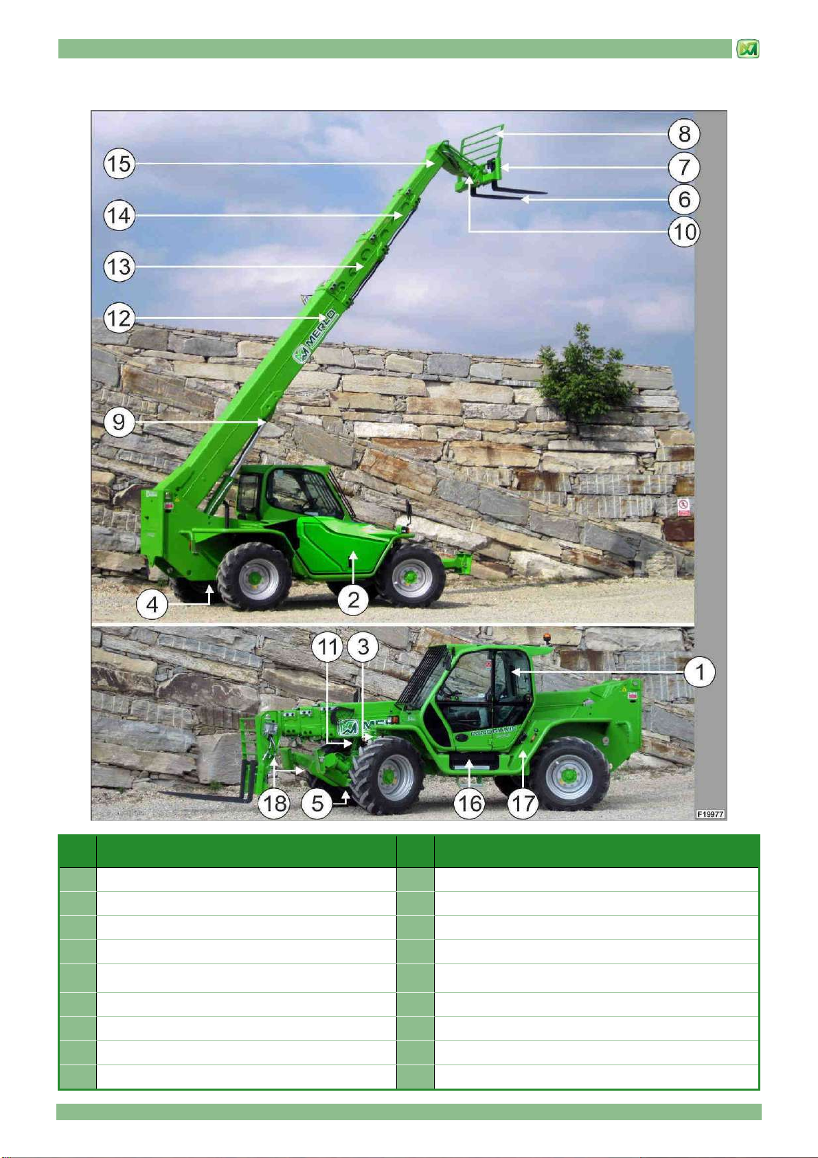
NOMENCLATURE MACHINE EXTERIOR
Please, pay attention to the identification of the machine sides, because they will be re quoted in the manual.
REF. DESCRIPTION
A Front side
B Rear side
C Left-hand side
D Right-hand side
P37.12 PLUS - P40.9 PLUS
REF.
DESCRIPTION REF.
DESCRIPTION
1 Operator cab 9 Fork tilt jack
2 Engine compartment and battery compartment 10 Crossways tilt correction jacks
3 Front axle - brake callipers - wheel reducers 11 First boom
4 Rear axle - brake callipers - parking brake calliper -
wheel reducers 12 Second boom
5 Forks 13 Third boom ((only P37.12 PLUS)
6 Attachment carriage 14 Fuel tank
7 Protection on carriage 15 Hydraulic oil tank
8 Telescopic boom lifting jacks
2 - MACHINE TECHNICAL INFORMATION
2 - 3
P38.12 PLUS - P38.13 PLUS – P38.12 – P38.13 – P38.13EE
REF.
DESCRIPTION REF.
DESCRIPTION
1 Operator cab 9 Fork tilt jack
2 Engine compartment and battery compartment 10 Crossways angle correction jacks
3 Front axle - brake callipers - wheel reducers 11 First boom
4 Rear axle - brake callipers - parking brake calliper -
wheel reducers 12 Second boom
5 Forks 13 Third boom
6 Attachment carriage 14 Fuel tank
7 Protection on carriage 15 Hydraulic oil tank
8 Telescopic boom lifting jacks 16 Stabilisers
2 - MACHINE TECHNICAL INFORMATION
2 - 4
P38.14 PLUS – P38.14
REF.
DESCRIPTION REF.
DESCRIPTION
1 Operator cab 9 Fork tilt jack
2 Engine compartment and battery compartment 10 Crossways angle correction jacks
3 Front axle - brake callipers - wheel reducers 11 First boom
4 Rear axle - brake callipers - parking brake calliper -
wheel reducers 12 Second boom
5 Forks 13 Third boom
6 Attachment carriage 14 Fuel tank
7 Protection on carriage 15 Hydraulic oil tank
8 Telescopic boom lifting jacks 16 Stabilisers
2 - MACHINE TECHNICAL INFORMATION
2 - 5
P40.17 PLUS – P40.17 – P40.17EE
REF.
DESCRIPTION REF.
DESCRIPTION
1 Operator cab 10 Telescopic boom lifting jack
2 Engine and battery compartment 11 Fork tilt jack
3 Electronic control unit compartment 12 Crossways angle correction jacks
4 Rear axle - brake callipers - wheel reducers 13 First boom
5 Front axle - brake callipers - parking brake calliper -
wheel reducers 14 Second boom
6 Forks 15 Third boom
7 Attachment carriage 16 Fourth boom
8 Protection on carriage 17 Fuel tank
9 Telescopic boom lifting jack 18 Hydraulic oil tank
2 - MACHINE TECHNICAL INFORMATION
2 - 6
P60.10 - P72.10 – P60.10EE – P72.10EE
REF.
DESCRIPTION REF.
DESCRIPTION
1 Operator cab 8 Telescopic boom lifting jacks
2 Engine compartment and battery compartment 9 Fork tilt jack
3 Front axle - brake callipers - wheel reducers 10 Crossways angle correction jacks
4 Rear axle - brake callipers - parking brake calliper -
wheel reducers 11 First boom
5 Forks 12 Second boom
6 Attachment carriage 13 Fuel tank
7 Protection on carriage 14 Hydraulic oil tank
2 - MACHINE TECHNICAL INFORMATION
2 - 7
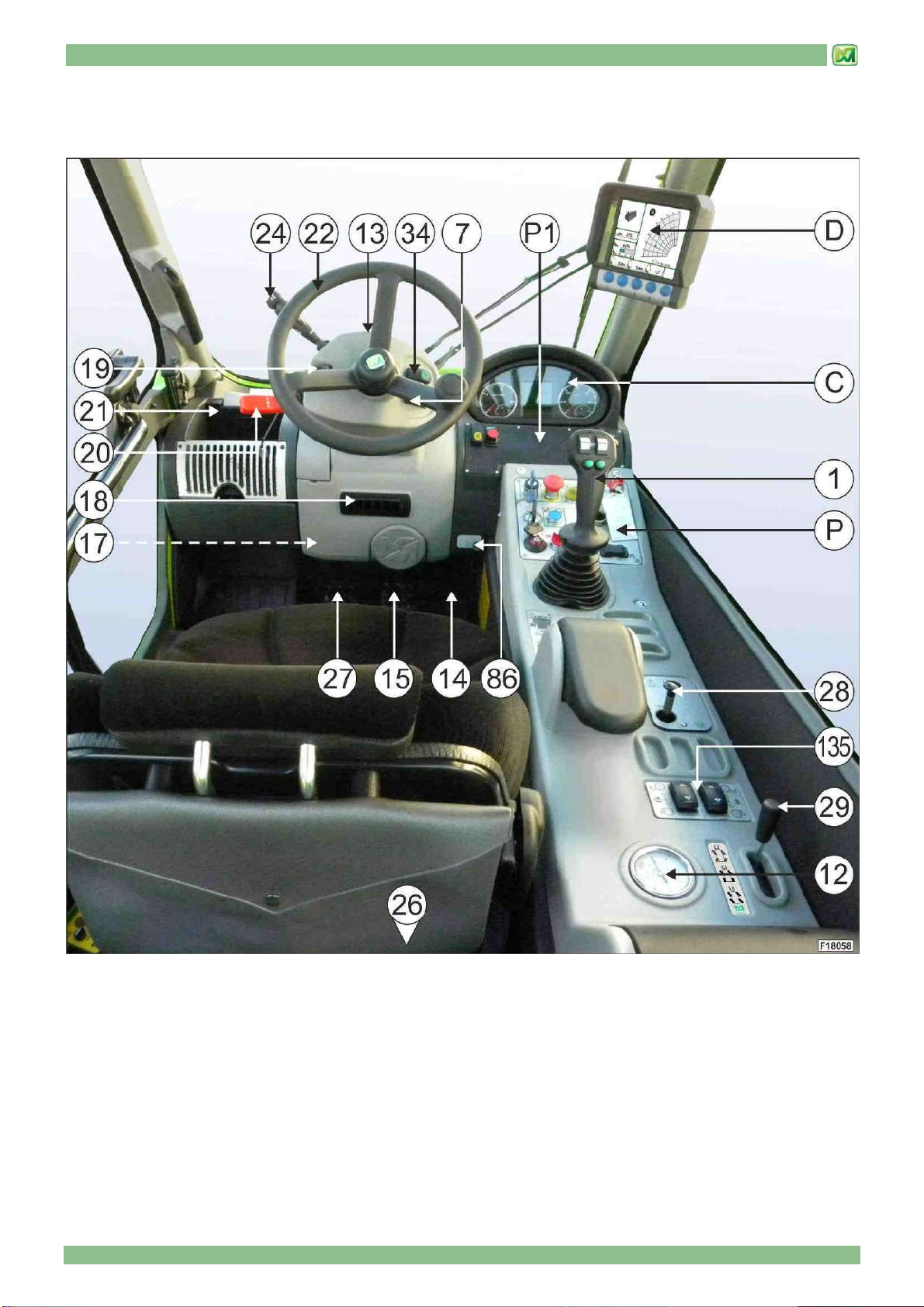
CAB INTERIOR KEY WORD
(only for models P37.12PLUS – P38.12PLUS – P38.13PLUS – P38.14PLUS – P40.9PLUS – P40.17PLUS – P60.10 – P72.10)

2 - MACHINE TECHNICAL INFORMATION
2 - 8
REF. DESCRIPTION
1 Telescopic boom control joystick
7 Rear windscreen-wiper switch
12 Pressure gauge for hydraulic system oil or hydrostatic transmission system
13 Spirit level
14 Accelerator pedal
15 Brake pedal
17 Steering wheel trim lock lever
18 Air vent
19 Gear control
20 Drive direction selector
21 Load chart and safety instruction holder
22 Steering wheel
24 Parking lights switch/ low beam lights / Direction indicators / head lights / Horn
26 Lever for the selection of the air suction from inside/outside the cab
27 Driving speed adjustment pedal
28 Small emergency pump for releasing parking brake
29 Steering mode selection lever
34 Front windscreen wiper and screen-washer switch
86 Hand accelerator
135 Stabiliser command switches
(only for models P38.12 PLUS – P38.13 PLUS – P38.14 PLUS – P40.17 PLUS)
C Instrument panel
D Attachments dynamic control display
P – P1 Control panels
2 - MACHINE TECHNICAL INFORMATION
2 - 9
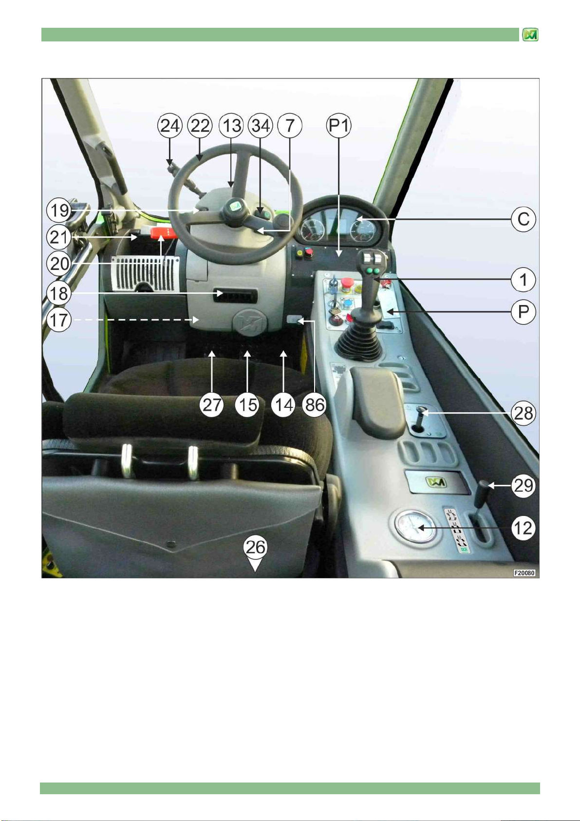
(only for models P60.10EE – P72.10EE)
Table of contents
Popular Truck manuals by other brands


freightliner
freightliner Custom Classic MT45 2022 Maintenance manual

Komatsu
Komatsu Galeo HD605-7E0 brochure

Trane
Trane Thermo King TriPac EVOLUTION installation manual

Mitsubishi
Mitsubishi Fuso FK 2008 owner's manual

Clarke
Clarke PT550BD Operation & maintenance instructions

Haklift
Haklift HAVA1200ELE Original instructions