Hyster B274 Operating instructions

Hyster B274 (H50CT) Internal Combustion Engine
Trucks Service Repair Manual

ELECTRICAL SYSTEM
S50CT [B267];
H2.0-2.5CT (H50CT) [B274]
PART NO. 4120745 2200 SRM 1771

SAFETY PRECAUTIONS
MAINTENANCE AND REPAIR
• The Service Manuals are updated on a regular basis, but may not reflect recent design changes to the
product. Updated technical service information may be available from your local authorized Hyster®
dealer. Service Manuals provide general guidelines for maintenance and service and are intended for
use by trained and experienced technicians. Failure to properly maintain equipment or to follow in-
structions contained in the Service Manual could result in damage to the products, personal injury,
property damage or death.
• When lifting parts or assemblies, make sure all slings, chains, or cables are correctly fastened, and
that the load being lifted is balanced. Make sure the crane, cables, and chains have the capacity to
support the weight of the load.
• Do not lift heavy parts by hand, use a lifting mechanism.
• Wear safety glasses.
• DISCONNECT THE BATTERY CONNECTOR before doing any maintenance or repair on electric lift
trucks. Disconnect the battery ground cable on internal combustion lift trucks.
• Always use correct blocks to prevent the unit from rolling or falling. See HOW TO PUT THE LIFT
TRUCK ON BLOCKS in the Operating Manual or the Periodic Maintenance section.
• Keep the unit clean and the working area clean and orderly.
• Use the correct tools for the job.
• Keep the tools clean and in good condition.
•Always use HYSTER APPROVED parts when making repairs. Replacement parts must meet or ex-
ceed the specifications of the original equipment manufacturer.
• Make sure all nuts, bolts, snap rings, and other fastening devices are removed before using force to
remove parts.
• Always fasten a DO NOT OPERATE tag to the controls of the unit when making repairs, or if the unit
needs repairs.
•Be sure to follow the WARNING and CAUTION notes in the instructions.
• Gasoline, Liquid Petroleum Gas (LPG), Compressed Natural Gas (CNG), and Diesel fuel are flamma-
ble. Be sure to follow the necessary safety precautions when handling these fuels and when working
on these fuel systems.
• Batteries generate flammable gas when they are being charged. Keep fire and sparks away from the
area. Make sure the area is well ventilated.
NOTE: The following symbols and words indicate safety information in this
manual:
WARNING
Indicates a hazardous situation which, if not avoided, could result in death
or serious injury.
CAUTION
Indicates a hazardous situation which, if not avoided, could result in minor
or moderate injury and property damage.
On the lift truck, the WARNING symbol and word are on orange back-
ground. The CAUTION symbol and word are on yellow background.

©2014 HYSTER COMPANY
TABLE OF CONTENTS
General .....................................................................................................................................................................1
Engine Control Module (ECM), Yanmar Diesel Engine ....................................................................................... 2
Remove ................................................................................................................................................................ 2
Install ...................................................................................................................................................................2
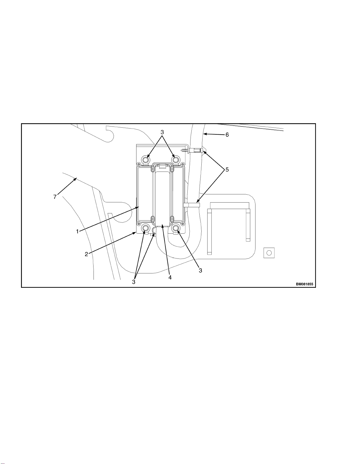
Display Switch Cluster ........................................................................................................................................... 3
Remove ................................................................................................................................................................ 3
Install ...................................................................................................................................................................5
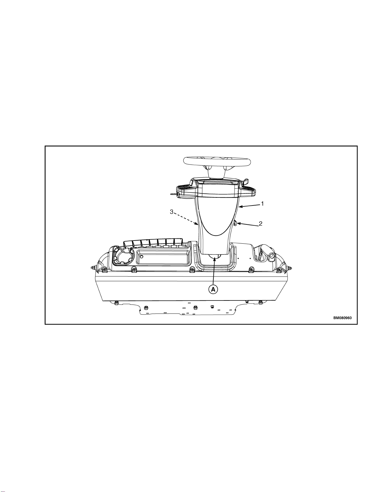
Direction Control Lever ...................................................................................................................................... 5
Remove ............................................................................................................................................................ 5
Install .............................................................................................................................................................. 6
Key Switch ...........................................................................................................................................................6
Remove ............................................................................................................................................................ 6
Install .............................................................................................................................................................. 7
Display Switch Cluster Panel Bezel and Overlay ............................................................................................. 7
Remove ............................................................................................................................................................ 7
Install .............................................................................................................................................................. 7
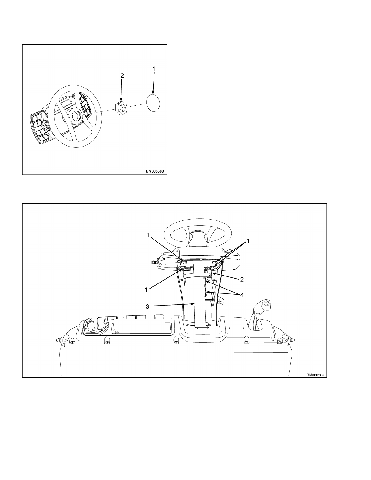
Steering Column Repair ......................................................................................................................................... 8
Remove ................................................................................................................................................................ 8
Disassemble .........................................................................................................................................................9
Assemble ............................................................................................................................................................10
Install .................................................................................................................................................................10
Sensors and Switches ............................................................................................................................................10
General .............................................................................................................................................................. 10
Dash Panel, Kick Panel, and Seal Plate, Remove and Install ................................................................... 10
Remove ......................................................................................................................................................10
Install ........................................................................................................................................................11
Accelerator Pedal Position Sensor ................................................................................................................... 12
Remove .......................................................................................................................................................... 12
Install ............................................................................................................................................................ 13
Brake Fluid Level Switch ................................................................................................................................. 13
Remove .......................................................................................................................................................... 13
Install ............................................................................................................................................................ 14
Brake Pedal Position Sensor ............................................................................................................................ 14
Remove .......................................................................................................................................................... 14
Install ............................................................................................................................................................ 15
Parking Brake Position Sensor ........................................................................................................................ 16
Remove .......................................................................................................................................................... 16
Install ............................................................................................................................................................ 16
Seat Sensor (Operator Presence System) ........................................................................................................ 16
Non-Suspension Seat ....................................................................................................................................16
Remove ......................................................................................................................................................16
Install ........................................................................................................................................................18
Full Suspension Seats .................................................................................................................................. 18
Remove ......................................................................................................................................................18
Install ........................................................................................................................................................18
Transmission Pressure Sensors (Transducers) ............................................................................................... 19
Remove .......................................................................................................................................................... 19
Install ............................................................................................................................................................ 19
Transmission Temperature Sensor ..................................................................................................................19
Remove .......................................................................................................................................................... 19
Table of Contents
i

TABLE OF CONTENTS (Continued)
Install ............................................................................................................................................................ 20
Rear Horn Button Switch .................................................................................................................................20
Remove .......................................................................................................................................................... 20
Install ............................................................................................................................................................ 20
Engine and Fuel Sensors and Switches, PSI 2.4L Dual Fuel Trucks ............................................................ 21
Engine and Fuel Sensors, Yanmar 2.6L Diesel Trucks .................................................................................. 21
Engine Speed Sensor .................................................................................................................................... 21
Remove ......................................................................................................................................................21
Install ........................................................................................................................................................22
Oil Pressure Sensor ...................................................................................................................................... 22
Remove ......................................................................................................................................................22
Install ........................................................................................................................................................22
Engine Coolant Temperature (ECT) Sensor ............................................................................................... 22
Remove ......................................................................................................................................................22
Install ........................................................................................................................................................22
Fuel/Water Separator Sensor .......................................................................................................................22
Remove ......................................................................................................................................................22
Install ........................................................................................................................................................23
Glow Plug Relay ............................................................................................................................................23
Remove ......................................................................................................................................................23
Install ........................................................................................................................................................26
Power Distribution Module (PDM) and Component Parts ................................................................................. 26
Power Distribution Module (PDM) as a Unit .................................................................................................. 26
Remove .......................................................................................................................................................... 26
Install ............................................................................................................................................................ 27
Power Distribution Module (PDM) Components .............................................................................................28
Remove and Install .......................................................................................................................................28
Battery ................................................................................................................................................................... 28
Remove .............................................................................................................................................................. 28
Install .................................................................................................................................................................28
Lights ..................................................................................................................................................................... 29
Work Lights (Front and Rear) ..........................................................................................................................29
Remove .......................................................................................................................................................... 29
Install ............................................................................................................................................................ 29
Strobe Light .......................................................................................................................................................29
Remove .......................................................................................................................................................... 29
Install ............................................................................................................................................................ 30
LED Tail, Backup, and Brake Lights .............................................................................................................. 30
Remove .......................................................................................................................................................... 30
Install ............................................................................................................................................................ 31
Reflectors ...........................................................................................................................................................31
Remove .......................................................................................................................................................... 31
Install ............................................................................................................................................................ 31
This section is for the following models:
(S50CT) [B267];
H2.0-2.5CT (H50CT) [B274]
Table of Contents
ii

Thanks very much for your reading,
Want to get more information,
Please click here, Then get the complete
manual
NOTE:
If there is no response to click on the link above,
please download the PDF document first, and then
click on it.
Have any questions please write to me:
admin@servicemanualperfect.com

General
The removal and replacement procedures for the
following electrical components are covered in this
manual:
• Display Switch Cluster
• Power Distribution Module (PDM)
• Lights
• Sensors and switches
• Battery
Some of the components used are made of plastic.
When using screws to replace and install plastic
components, the screws should be rotated
counterclockwise until the screw thread turns over
the last thread in the plastic part. The screw can
then be turned clockwise to make a connection.
This prevents "cutting" new threads and damaging
the existing thread in the plastic part.
If any welding must be done, obtain proper
authorization from a Resident Service Engineer. If
authorization is given, be sure to follow the
procedures in the CAUTION below.
CAUTION
When welding, always disconnect the negative
battery cable from battery and disconnect the
ground wire from the ground stud on the frame.
See Figure 1. To prevent damage to the Electronic
Control Unit (ECU), remove it from the lift truck.
For lift trucks equipped with LPG engine see Fuel
System PSI 2.4L 0900SRM1757 for procedure to
remove ECU from lift truck.
For lift trucks equipped with diesel engines see
section Engine Control Module (ECM), Yanmar
Diesel Engine in this manual for procedure to
remove ECM from lift truck.
NOTE: VIEW SHOWN IS FROM THE LEFT SIDE.
MAJOR COMPONENTS AND ELECTRICAL
CONNECTIONS NOT SHOWN FOR CLARITY.
1. GROUND STUD
2. TANK OPENING FOR HYDRAULIC FILTER
3. POWER DISTRIBUTION MODULE (PDM)
4. BATTERY
Figure 1. Welding Preparation
For more information on how to perform welding
repairs to lift truck and overhead guard, see
Periodic Maintenance 8000SRM1774.
2200 SRM 1771 General
1

Engine Control Module (ECM), Yanmar Diesel Engine
REMOVE
NOTE: ECM for Yanmar engine is located on left-
hand side of frame.
1. Disconnect negative battery cable.
2. Remove two conduit clips from wire harness
and bracket. See Figure 2.
3. Disconnect ECM connector from ECM. See Fig-
ure 2.
4. Remove four capscrews and ECM from bracket.
See Figure 2.
5. Remove capscrew and bracket from frame. See
Figure 2.
1. ECM
2. BRACKET
3. CAPSCREW
4. ECM CONNECTOR
5. CONDUIT CLIP
6. WIRE HARNESS
7. FRAME
Figure 2. ECM, Yanmar Diesel Engine
INSTALL
1. Install bracket and capscrew on frame. See Fig-
ure 2.
2. Install ECM and four capscrews on bracket. See
Figure 2.
3. Connect ECM connector to ECM. See Figure 2.
4. Install two conduit clips to wire harness and
bracket. See Figure 2.
5. Connect negative battery cable.
Engine Control Module (ECM), Yanmar Diesel Engine 2200 SRM 1771
2

Display Switch Cluster
REMOVE
NOTE: The Display Switch Cluster is a non-repair-
able part. See Parts Manual for replacement part
number.
1. Disconnect ground wire.
2. Lift up on the steering wheel slightly and pull
up on the tilt lever. Fully lower the steering col-
umn.
3. Remove upper steering column cover by pulling
up on upper steering column cover to release
the latches (one on either side), and pulling
cover away from steering column. See Figure 3.
NOTE: TOP VIEW OF DASH SHOWN.
A. INDICATES TO PULL UP TO UNLATCH
1. UPPER STEERING COLUMN COVER
2. STEERING COLUMN TILT LEVER
3. LOWER STEERING COLUMN COVER
Figure 3. Upper Steering Column Cover Removal
4. Remove the horn button and disconnect the
horn wires.
NOTE: A puller tool may be required to remove the
steering wheel.
5. Remove the lock nut securing the steering
wheel and remove steering wheel from steering
column. Take care to not damage the horn
wires. See Figure 4.
2200 SRM 1771 Display Switch Cluster
3

Figure 4. Steering Wheel Removal
Legend for Figure 4
1. HORN BUTTON
2. LOCK NUT
6. Disconnect the Display Switch Cluster harness
from the Display Switch Cluster. Remove the
four bolts securing the Display Switch Cluster.
Slide the display panel off of the steering col-
umn. See Figure 5.
NOTE: TOP DOWN VIEW SHOWN.
1. BOLTS
2. DISPLAY SWITCH CLUSTER HARNESS
3. STEERING COLUMN
4. HORN WIRES (CONTACT PADS)
Figure 5. Display Switch Cluster Removal
Display Switch Cluster 2200 SRM 1771
4

INSTALL
1. Install Display Switch Cluster onto steering
column. Install four bolts to secure panel to
steering column and tighten bolts to
19 N•m (168 lbf in). See Figure 5.
2. Connect the Display Switch Cluster to the dis-
play harness.
3. Install steering wheel onto steering shaft and
tighten the lock nut until steering wheel is fully
seated. The final torque for the lock nut is 40 to
54 N•m (30 to 40 lbf ft). See Figure 4.
4. Connect horn wires to horn button. Install horn
lock nut and horn button into steering wheel.
5. Install upper steering column cover by aligning
the two latches and pushing down until
latched. See Figure 3.
DIRECTION CONTROL LEVER
Remove
NOTE: The direction control lever is located on left
side of Display Switch Cluster. The direction con-
trol lever is non-repairable and must be replaced as
an assembly. See the Parts Manual for replace-
ment part number.
1. Insert two small, flat-blade or Phillips screw-
drivers, with a 3.175 mm (0.125 in.) or less,
wide blade or die end, into the opening on the
Display Switch Cluster on an outward angle
enough to compress the spring tab on the direc-
tion control lever. See A, Figure 6.
2200 SRM 1771 Display Switch Cluster
5

NOTE: DISPLAY SWITCH CLUSTER SHOWN OUTSIDE OF LIFT TRUCK FOR CLARITY. FLAT-BLADE
SCREWDRIVERS SHOWN.
A. STEP 1 B. STEP 2
1. DIRECTION CONTROL LEVER
2. FLAT-BLADE SCREWDRIVER
3. DISPLAY SWITCH CLUSTER
Figure 6. Direction Control and Turn Signal Removal
2. Pry the spring tab toward the body of the direc-
tion control lever or turn signal lever and, at
the same time, pull on the handle of the lever
enough to free the tab of the interior lock of the
Display Switch Cluster. See B, Figure 6.
3. Repeat the previous steps on the opposite side
of the direction control lever. Remove the direc-
tion control lever from the Display Switch Clus-
ter.
Install
Install the direction control lever into the opening
of the Display Switch Cluster until the locking tabs
are engaged in the Display Switch Cluster.
KEY SWITCH
Remove
1. Fully lower the steering column and remove the
upper steering column cover by pushing in on
both sides of the cover to release the latches
(one on either side), and pulling cover away
from steering column. See Figure 3.
2. Remove torx head capscrews. See Figure 7.
Display Switch Cluster 2200 SRM 1771
6

1. BEZEL
2. OVERLAY
3. KEY SWITCH
4. TORX HEAD SCREW
5. INSERT SCREWDRIVER IN SLOT AT THIS LO-
CATION
Figure 7. Display Switch Cluster Panel Bezel, Grid, and Key Switch Removal
3. Slide key switch assembly out of Display
Switch Cluster. See Figure 7.
Install
1. Install new key switch assembly into Display
Switch Cluster. Install torx head capscrews
(T-15) to secure key switch to Display Switch
Cluster. Tighten torx head capscrews to
1.1 N•m (9.7 lbf in). See Figure 7.
2. Install upper steering cover on steering column.
Align latches on upper steering cover to holes
on steering column and push upper steering
cover into place on steering column.
DISPLAY SWITCH CLUSTER PANEL
BEZEL AND OVERLAY
Remove
1. Insert a small, flat-bladed screwdriver into the
top slot on the inner edge of the bezel and pry
outward. Repeat procedure at the lower slot on
the bezel. Be careful to not damage bezel and
overlay when removing bezel. Lift bezel off of
Display Switch Cluster. See Figure 7.
2. Remove overlay from Display Switch Cluster.
Install
Place new overlay on display panel and install a
new bezel by inserting the outer edge in the display
and then pressing down the inner edge.
2200 SRM 1771 Display Switch Cluster
7

Steering Column Repair
REMOVE
1. Raise hood. Disconnect battery.
2. Remove floor mat and floor plate. See Frame
0100SRM1766 for removal procedure. Remove
kick panel, dash panel, and seal plate. See
Dash Panel, Kick Panel, and Seal Plate, Re-
move and Install for procedures.
3. Lower steering column to its lowest position.
4. Remove upper steering column cover by pulling
up on base of upper steering column cover to re-
lease latches (one on either side), and pulling
cover away from steering column. See Figure 3.
5. Remove steering wheel and instrument display
panel. See section Display Switch Cluster for
removal procedures.
6. Remove two screws and remove lower steering
column cover. See Figure 8.
1. SCREWS
2. LOWER STEERING COLUMN COVER
Figure 8. Lower Steering Column Cover
Steering Column Repair 2200 SRM 1771
8

7. Disconnect Display Switch Cluster harness
from display panel. Remove harness from steer-
ing column.
8. Remove four bolts (1, Figure 9) holding steering
column to cowl.
9. Raise steering column to disengage steering
shaft from steering control unit.
DISASSEMBLE
1. Remove steering shaft retention clip. See Fig-
ure 9.
2. Remove horn contact pads. See Figure 9.
1. BOLTS
2. PIVOT BOLTS
3. HORN WIRES
4. STEERING SHAFT RETENTION CLIP
5. HORN HARNESS
6. STEERING COLUMN
7. GAS CYLINDER
8. COWL
9. LOWER STRUT PIVOT PIN
10. HYDRAULIC CONTROL VALVE
11. STEERING CONTROL UNIT (SCU)
12. STEERING SHAFT
13. HORN CONTACT PADS
Figure 9. Steering Column
3. Remove lower strut pivot pin from gas cylinder.
See Figure 9.
4. Remove steering column pivot bolts and steer-
ing shaft. See Figure 9.
2200 SRM 1771 Steering Column Repair
9

ASSEMBLE
1. Install steering shaft and install steering col-
umn pivot bolts. See Figure 9.
2. Install lower strut pivot pin in the gas cylinder.
See Figure 9.
3. Install horn contact pads. See Figure 9.
4. Install steering shaft retention clip. See Fig-
ure 9.
INSTALL
1. Lubricate end of steering shaft with multipur-
pose grease. Install end of steering shaft into
steering control unit.
2. Using four bolts, install steering column to
cowl. Tighten bolts to 38 N•m (28 lbf ft). See
Figure 9.
3. Connect Display Switch Cluster harness to Dis-
play Switch Cluster panel. Install Display
Switch Cluster harness onto steering column.
4. Install lower steering column cover and two
screws onto steering column. See Figure 8.
5. Install instrument display panel and steering
wheel. See section Display Switch Cluster for
procedures.
6. Move steering column to it lowest position. In-
stall upper steering column cover by aligning
two latches and pushing down until latched.
See Figure 3.
7. Install floor plate, floor mat, and seal plate. See
Frame 0100SRM1766 for procedures.
8. Install kick panel and dash panel. See Dash
Panel, Kick Panel, and Seal Plate, Remove and
Install for procedures.
9. Connect battery and lower hood.
Sensors and Switches
GENERAL
CAUTION
Before removing and replacing any sensors or
switches, ALWAYS disconnect the battery. Failure
to disconnect the battery can cause damage to
the sensor or switch and other electrical compo-
nents. Always cover or protect the sensor or
switch connector from contamination after dis-
connecting the harness mating part.
DO NOT use solvent-based cleaners to clean area
around sensors or switches.
All sensors and switches used on these trucks are
non-repairable parts. Replace with new sensors or
switches whenever a sensor or switch malfunctions
and is not operating correctly. See Parts Manual
for replacement part numbers. Before installing
new sensors or switches, use a clean cloth and
make sure the area around the sensor or switch is
clean and free of oils and contaminates.
When removing and replacing sensors or switches,
be sure to tag connectors to aid in correct recon-
necting.
Dash Panel, Kick Panel, and Seal Plate,
Remove and Install
Remove dash panel, kick panel, and seal plate be-
fore removing and replacing the following sensors
and switches:
• Accelerator pedal position sensor
• Brake fluid level switch
• Service brake pedal position sensor
• Park brake sensor
After replacement of sensors and switches the dash
and kick panels need to be installed on lift truck.
Remove
1. Lower the steering column to its lowest posi-
tion.
Steering Column Repair 2200 SRM 1771
10

2. Remove upper steering column cover. See sec-
tion Steering Column Repair for procedures.
3. Remove five Allen Head screws securing the
dash panel to the top of the cowl. See Figure 10.
4. Pull kick panel up from bottom and out to re-
move kick panel from seal plate and clips on
dash.
5. Remove dash panel from cowl.
6. Remove three capscrews from seal plate and re-
move seal plate. See Figure 10.
1. ALLEN HEAD SCREWS
2. COWL
3. DASH PANEL
4. KICK PANEL
5. KICK PANEL NOTCHES
6. SEAL PLATE
7. CAPSCREWS
8. CLIPS
Figure 10. Dash Panel, Kick Panel, and Seal Plate Removal
Install
1. Using three capscrews, install seal plate.
Tighten capscrews to 10.8 N•m (95.6 lbf in).
See Figure 10.
2. Place dash panel on cowl and secure dash to
cowl using five Allen Head screws. Tighten Al-
len Head screws to 3.5 N•m (31 lbf in).
3. Align notches on kick panel to clips on dash and
push kick panel into place on seal plate. See
Figure 10.
4. Install upper steering column cover. See section
Steering Column Repair for procedures.
2200 SRM 1771 Sensors and Switches
11

ACCELERATOR PEDAL POSITION
SENSOR
Remove
1. To access the battery, raise the hood. Discon-
nect the battery.
2. Remove upper steering column cover (see Dis-
play Switch Cluster) and the dash and kick
panel. See Dash Panel, Kick Panel, and Seal
Plate, Remove and Install.
3. Remove lever bracket capscrews and move hy-
draulic lever assembly toward operator seat.
See Figure 11.
1. LEVER BRACKET CAPSCREWS
2. COWL
Figure 11. Hydraulic Control Valve Removal
NOTE: Tag electrical connectors prior to disconnect
to aid in correct reconnect.
4. Disconnect throttle position sensor from wiring
harness.
5. Remove three bolts, throttle base, and pedal as-
sembly from cowl. See Figure 12.
1. BOLTS
2. PEDAL ASSEMBLY
3. COWL
Figure 12. Accelerator Pedal and Throttle Base
Removal
6. Remove two pan head screws, two lockwashers,
and throttle position sensor from throttle base.
See Figure 13.
Sensors and Switches 2200 SRM 1771
12

1. PAN-HEAD SCREW
2. LOCKWASHER
3. THROTTLE POSITION SENSOR
4. THROTTLE BASE
5. D SHAPED THROTTLE SHAFT END
Figure 13. Throttle Position Sensor
Install
1. Insert new throttle position sensor into opening
on throttle base plate. See Figure 13.
2. Rotate sensor so that the D shaped throttle
shaft end slides into throttle position sensor.
See Figure 13.
3. Rotate sensor counterclockwise until locating
pin on sensor lines up with hole in throttle base
plate.
4. Install throttle position sensor onto throttle
base using two lockwashers and two pan head
screws. Tighten screws to 2.25 N•m (20 lbf in).
5. Install throttle base plate, pedal assembly, and
three bolts onto cowl. Tighten bolts to 19 to
25 N•m (168 to 221 lbf in). See Figure 12.
6. Connect throttle position sensor connector to
wiring harness as tagged during removal.
7. Install lever bracket onto cowl. Install clevis
and retention pins, and connect levers to con-
trol valve. See Figure 11.
8. Install kick panel and dash. See Dash Panel,
Kick Panel, and Seal Plate, Remove and Install
for installation procedures.
9. Install upper steering column cover. See Dis-
play Switch Cluster.
10. Connect battery and lower the hood.
11. Adjust throttle pedal stop, see Frame
0100SRM1766 for adjustment procedure.
BRAKE FLUID LEVEL SWITCH
Remove
NOTE: The brake fluid level switch is a component
of the brake fluid reservoir, located inside the res-
ervoir. When the switch is replaced, the reservoir
must be replaced as well.
2200 SRM 1771 Sensors and Switches
13

1. Raise the hood. Disconnect the battery.
2. Lower steering column to lowest position and
remove upper steering column cover (see Dis-
play Switch Cluster) and the dash and kick
panel). See Dash Panel, Kick Panel, and Seal
Plate, Remove and Install.
NOTE: Tag electrical connector prior to disconnect-
ing to aid in correct reconnect.
3. Disconnect brake fluid level switch from cowl
harness.
CAUTION
Disposal of lubricants and fluids must meet local
environmental regulations.
NOTE: Tag and plug hose during removal to aid in
installation.
4. Remove reservoir from bracket and drain fluid
from reservoir. Disconnect reservoir supply
hose from reservoir. Plug hose to prevent air
from getting into hose. See Figure 14.
Figure 14. Brake Fluid Level Switch
Legend for Figure 14
1. RESERVOIR SUPPLY HOSE
2. BRAKE FLUID RESERVOIR
3. COWL
4. BRAKE FLUID LEVEL SWITCH (INSIDE RESER-
VOIR)
5. BRAKE FLUID RESERVOIR MOUNTING
BRACKET
Install
1. Connect reservoir supply hose to a new reser-
voir. See Figure 14.
2. Install new reservoir onto bracket and fill with
new brake fluid. See Periodic Maintenance
8000SRM1774 for brake fluid specifications.
3. Connect brake fluid level switch to cowl har-
ness.
4. Install kick panel and dash. See Dash Panel,
Kick Panel, and Seal Plate, Remove and Install
for procedures. Install upper steering column
cover. See Display Switch Cluster for proce-
dures.
5. Connect the battery and lower the hood.
BRAKE PEDAL POSITION SENSOR
Remove
1. Raise the hood. Disconnect the battery.
2. Remove upper steering column cover (see Dis-
play Switch Cluster) and the dash and kick
panel. See Dash Panel, Kick Panel, and Seal
Plate, Remove and Install.
NOTE: Tag electrical connector prior to disconnect
to aid in correct reconnect.
3. Disconnect brake pedal position sensor from
cowl harness. See Figure 15.
Sensors and Switches 2200 SRM 1771
14
This manual suits for next models
1
Table of contents
Other Hyster Truck manuals