Big Joe PDBB-20-T12 Use and care manual

Big Joe Manufacturing Company • Des Plaines, IL 60018 MANUAL NO. 901357
Rev C, 12/08/06
PDBB-20-T12
POWER DRIVE INTERMEDIATE
LIFT TRUCK
Serial Number 375067 and Higher
Operation
Maintenance
Repair Parts List


901357 i
TABLE OF CONTENTS
Section Page Section Page
1 DESCRIPTION ............................................................1-1
1-1. INTRODUCTION. .............................................1-1
1-2. GENERAL DESCRIPTION...............................1-1
1-3. SAFETY FEATURES. ......................................1-2
2 OPERATION ...............................................................2-1
2-1. GENERAL. .......................................................2-1
2-2. OPERATING PRECAUTIONS. ........................2-1
2-3. BEFORE OPERATION.....................................2-1
2-4. POWER DRIVE CONTROL HANDLE..............2-4
2-4.1. CONTROL HANDLE. .......................................2-4
2-4.2. STEERING ARM CONTROLS. ........................2-4
2-4.3. DRIVING AND STOPPING PROCEDURES. ...2-4
2-5. BELLY-BUTTON SWITCH GUARD. ................2-5
2-6. STEERING ARM RETURN SPRING. ..............2-5
2-7. LIFT/LOWER/STOP CONTROL.......................2-5
2-1. PARKING. ........................................................2-5
3 PLANNED MAINTENANCE ........................................3-1
3-1. GENERAL. .......................................................3-1
3-2. MONTHLY AND QUARTERLY CHECKS. .......3-1
3-3. GEL CELL BATTERY CARE............................3-1
3-3.1. GENERAL. .......................................................3-1
3-3.2. CHARGING BATTERIES .................................3-1
3-3.3. REMOVING BATTERIES FROM CHARGER ..3-3
3-4. LUBRICATION. ................................................3-3
3-5. LIFT CHAIN MAINTENANCE...........................3-3
4 TROUBLESHOOTING ................................................4-1
4-1. GENERAL ........................................................4-1
4-2. GEL CELL BATTERY CHARGER 004987
TROUBLESHOOTING .....................................4-3
4-2.1. DIP SWITCH SETTING (Figure 4-1)................4-3
4-2.2. THERMISTOR..................................................4-3
4-2.3. CIRCUIT BREAKER TESTING ........................4-3
4-2.4. POWER TRANSFORMER TESTING...............4-3
4-2.5. CIRCUIT BOARD TESTING.............................4-3
4-3. TRANSISTOR CONTROLLER
TROUBLESHOOTING .....................................4-4
4-3.1. FAULT DETECTION. .......................................4-4
4-3.2. HAND HELD PROGRAMMER. ........................4-4
4-3.3. FAULT RECORDING. ......................................4-4
4-3.4. FAULT RECOVERY.........................................4-4
4-3.5. GENERAL CHECKOUT. ..................................4-5
4-3.6. ADJUSTMENT. ................................................4-5
4-3.7. DIAGNOSTICS AND TROUBLESHOOTING. ..4-6
5 STEERING ARM, CONTROL HEAD AND
PIVOT TUBE SERVICING ..........................................5-1
5-1. GENERAL. .......................................................5-1
5-2. BELLY-BUTTON SWITCH ADJUSTMENT. .....5-1
5-3. POTENTIOMETER TESTING AND
ADJUSTMENT .................................................5-3
5-4. CONTROL HEAD SWITCH REPLACEMENT..5-3
5-5. SPEED CONTROL SWITCH RETURN
SPRING REPLACEMENT................................5-3
5-6. STEERING ARM RETURN SPRING
ADJUSTMENT................................................. 5-4
5-7. STEERING ARM RETURN SPRING
REPLACEMENT. ............................................. 5-4
5-8. PIVOT TUBE FLANGED BUSHING
REPLACEMENT. ............................................. 5-6
5-9. ELECTRICAL CONTROL CABLE
REPLACEMENT. ............................................. 5-7
6 BRAKE SERVICING ................................................... 6-1
6-1. DEADMAN SWITCH ADJUSTMENT............... 6-1
6-2. DEADMAN SWITCH REPLACEMENT............ 6-1
6-3. ELECTRIC BRAKE.......................................... 6-4
6-3.1. BRAKE ADJUSTMENT SERIAL NUMBER
376500 TO 377143.......................................... 6-4
6-3.2. BRAKE ADJUSTMENT SERIAL NUMBER
377144 AND HIGHER ..................................... 6-4
6-3.3. REMOVAL ....................................................... 6-5
6-3.4. DISASSEMBLY AND REASSEMBLY ............. 6-5
6-3.5. INSTALLATION ............................................... 6-5
7 TRANSMISSION, DRIVE WHEEL, AND
LOAD WHEEL SERVICING........................................ 7-1
7-1. DRIVE WHEEL REMOVAL. ............................ 7-1
7-2. TRANSMISSION, MOTOR AND BRAKE
ASSEMBLY REMOVAL................................... 7-1
7-3. TRANSMISSION, MOTOR AND BRAKE
ASSEMBLY INSTALLATION........................... 7-3
7-4. LOAD WHEELS. .............................................. 7-4
8 ELEVATION SYSTEM SERVICING ........................... 8-1
8-1. GENERAL........................................................ 8-1
8-2. LIFT CHAIN WEAR INSPECTION................... 8-1
8-3. LIFT CHAIN LENGTH ADJUSTMENT............. 8-1
8-4. LIFT CHAIN REPLACEMENT. ........................ 8-1
8-5. LIFT CYLINDER REMOVAL............................ 8-1
8-6. RAM HEAD REMOVAL. .................................. 8-3
8-7. LUBRICATION OF MAST................................ 8-3
9 HYDRAULIC SYSTEM SERVICING........................... 9-1
9-1. RELIEVING SYSTEM PRESSURE. ................ 9-1
9-2. FLOW CONTROL VALVE REPLACEMENT. .. 9-1
9-3. SUCTION LINE FILTER REPLACEMENT. ..... 9-2
9-4. LINE OR FITTING REPLACEMENT................ 9-2
9-5. HYDRAULIC PUMP AND MOTOR
ASSEMBLY. .................................................... 9-3
9-5.1. PUMP AND MOTOR ASSEMBLY REMOVAL. 9-3
9-5.2. HYDRAULIC PRESSURE ADJUSTMENT. ..... 9-3
9-6. LIFT CYLINDER REPAIR................................ 9-3
10 ELECTRICAL COMPONENTS ................................. 10-1
10-1. BATTERIES................................................... 10-1
10-2. EMERGENCY POWER DISCONNECT ........ 10-3
10-3. ELECTRICAL CONTROL PANEL ................. 10-3
10-3.1.MAINTENANCE............................................. 10-3
10-3.2.CLEANING .................................................... 10-3

ii 901357
TABLE OF CONTENTS - Continued
Section Page Section Page
10-3.3.DIAGNOSTIC HISTORY................................ 10-3
10-3.4.TEST THE FAULT DETECTION CIRCUITRY10-5
10-3.5.PANEL REMOVAL ........................................ 10-5
10-3.6.PANEL DISASSEMBLY AND
REASSEMBLY............................................... 10-5
10-3.7.PANEL INSTALLATION ................................ 10-5
10-4. PUMP MOTOR. ............................................. 10-5
10-5. DRIVE MOTOR.............................................. 10-5
10-6. BATTERY CHARGER....................................10-5
10-7. TRAVEL LIMIT SWITCH. ...............................10-5
10-7.1. SERIAL NUMBER 375067 TO 377143.........10-5
10-7.2. SERIAL NUMBER 377144 AND HIGHER ....10-5
10-8. HORN.............................................................10-5
11 ILLUSTRATED PARTS BREAKDOWN .................... 11-1
LIST OF ILLUSTRATIONS
Figure Page Figure Page
1-1 NAME PLATE ..................................................... 1-1
1-2 PDBB-20-T12 LIFT TRUCK ................................ 1-3
2-1 SAMPLE OF OPERATOR CHECK LIST ............ 2-3
2-2 CONTROL HANDLE ........................................... 2-4
2-3 STEERING ARM BRAKING POSITION ............. 2-5
3-1 CHARGE INDICATOR ........................................ 3-2
4-1 DIP SWITCH SETTINGS .................................... 4-3
4-2 WIRING DIAGRAM (SHEET 1)......................... 4-10
4-3 WIRING DIAGRAM (SHEET 1)......................... 4-12
4-4 WIRING DIAGRAM (SHEET 1)......................... 4-14
4-5 ELECTRICAL SCHEMATIC (SHEET 1) ........... 4-16
5-1 BELLY-BUTTON SWITCH ADJUSTMENT......... 5-1
5-2 CONTROL HEAD ASSEMBLY ........................... 5-2
5-3 CONTROL HEAD POTENTIOMETER
ADJUSTMENT .................................................... 5-3
5-4 STEERING ARM AND ELECTRICAL CABLE .... 5-5
5-5 PIVOT TUBE AND TRANSMISSION
ASSEMBLY......................................................... 5-6
5-6 ELECTRICAL CONTROL CABLE
REPLACEMENT ................................................. 5-8
6-1 BRAKE ENGAGE/DISENGAGE ......................... 6-1
6-2 BRAKE AND ACTUATOR................................... 6-2
6-3 PIVOT TUBE AND TRANSMISSION
ASSEMBLY......................................................... 6-3
6-4 DUST RING REMOVAL...................................... 6-4
6-5 BRAKE ADJUSTMENT....................................... 6-4
6-6 TRANSMISSION/MOTOR/BRAKE ASSEMBLY. 6-5
7-1 TRANSMISSION/MOTOR/BRAKE ASSEMBLY. 7-1
7-2 PIVOT TUBE REMOVAL TOOL ......................... 7-1
7-3 PIVOT TUBE AND TRANSMISSION
ASSEMBLY......................................................... 7-2
7-4 LOAD WHEELS .................................................. 7-4
8-1 ELEVATION SYSTEM ........................................ 8-2
9-1 HYDRAULIC SYSTEM........................................ 9-1
9-2 LIFT CYLINDER.................................................. 9-4
10-1 BATTERIES AND EMERGENCY POWER
DISCONNECT .................................................. 10-1
10-2 BATTERIES AND EMERGENCY POWER
DISCONNECT .................................................. 10-2
10-3 EMERGENCY POWER DISCONNECT............ 10-4
10-4 CONTACTOR.................................................... 10-4
10-5 TRANSISTOR CONTROL ELECTRICAL
CONTACTOR PANEL ....................................... 10-6
10-6 ELECTRICAL COMPONENTS.......................... 10-7
11-1 CONTROL HEAD ASSEMBLY.......................... 11-2
11-2 STEERING ARM ............................................... 11-4
11-3 PIVOT TUBE ASSEMBLY................................. 11-5
11-4 BRAKE AND ACTUATOR ................................. 11-6
11-5 TRANSMISSION, MOTOR AND BRAKE ASSY 11-8
11-6 BASE AND FRAME........................................... 11-9
11-7 DECAL LOCATION ......................................... 11-10
11-8 LOAD WHEELS............................................... 11-11
11-9 ELEVATION SYSTEM..................................... 11-12
11-10 PLATFORM ..................................................... 11-14
11-11 BOOM, SELF RETRACTING LIFELINE AND
SAFETY BELT................................................. 11-15
11-12 HYDRAULIC SYSTEM .................................... 11-16
11-13 LIFT CYLINDER .............................................. 11-18
11-14 BATTERIES..................................................... 11-20
11-15 BATTERIES..................................................... 11-22
11-16 CHASSIS MOUNTED ELECTRICAL
COMPONENTS............................................... 11-24
11-17 PLATFORM MOUNTED ELECTRICAL
COMPONENTS............................................... 11-26
11-18 PLATFORM MOUNTED ELECTRICAL
COMPONENTS............................................... 11-28
11-19 DRIVE MOTOR ............................................... 11-30
11-20 HYDRAULIC PUMP AND MOTOR
ASSEMBLY ..................................................... 11-31
11-21 ELECTRICAL CONTROL PANEL ................... 11-32
11-22 EMERGENCY POWER DISCONNECT.......... 11-34
11-23 CONTACTOR.................................................. 11-35
11-24 GEL CELL BATTERY CHARGER................... 11-36
11-25 GEL CELL BATTERY CHARGER
INSTALLATION .............................................. 11-37
11-26 GEL CELL BATTERY CHARGER................... 11-38
11-27 GEL CELL BATTERY CHARGER
INSTALLATION ............................................... 11-39
11-28 GEL CELL BATTERY CHARGER................... 11-40

901357 iii
LIST OF TABLES
Table Page Table Page
2-1 OPERATOR CHECKS ...........................................2-2
3-1 MONTHLY AND QUARTERLY INSPECTION AND
SERVICE CHART ..................................................3-1
3-2 RECOMMENDED LUBRICANTS...........................3-3
3-3 LUBRICATION DIAGRAM......................................3-4
3-4 LUBRICATION CHART ..........................................3-4
4-1 TROUBLESHOOTING CHART ............................. 4-1
4-2 FAULT RECOVERY EXCEPTIONS. ..................... 4-4
4-3 ADJUSTMENT SETTINGS.................................... 4-6
4-4 LED CODES .......................................................... 4-6
4-5 TROUBLESHOOTING CHART ............................. 4-7

iv 901357
OPERATOR INSTRUCTIONS
WARNING
Do not operate this truck unless you have been trained
and authorized to do so and have read all warnings
and instructions in operator's manual and on this truck.
Do not operate this truck until you have checked its
condition. Give special attention to Tires, Horn, Lights,
Battery, Controller, Lift System, (including platform,
chains, cables and limit switches), Brakes, Steering
Mechanism, Guards and Safety Devices.
Operate truck only from designated operating position.
Never place any part of your body into the mast struc-
ture or between the mast and the truck. Do not carry
passengers. Keep feet clear of truck.
Observe applicable traffic regulations. Yield right of
way to pedestrians. Slow down and sound horn at
cross aisles and wherever vision is obstructed.
Start, stop, travel, steer and brake smoothly. Slow
down for turns and on uneven or slippery surfaces that
could cause truck to slide or overturn. Use special
care when traveling without load as the risk of overturn
may be greater.
Travel with lifting mechanism in the lower position.
Always look in direction of travel. Keep a clear view,
and when load interferes with visibility, travel with load
or lifting mechanism trailing, except when traveling
downhill.
Use special care when operating on ramps—travel
slowly, and do not angle or turn. Travel with lifting
mechanism or load downhill.
Do not overload truck. Trucks are designed to handle
loads up to 650 pounds at a 19” load center. Loads
include personnel.
Do not handle unstable or loosely stacked loads. Use
special care when handling long, high or wide loads to
avoid losing the load, striking bystanders, or tipping
the truck.
Elevate platform only to pick up or stack a load. Watch
out for obstructions, especially overhead.
Do not allow anyone to stand or pass under load or lift-
ing mechanism.
When leaving truck, neutralize travel control. Fully
lower lifting mechanism and set brake. When leaving
truck unattended, also shut off power and remove the
key.
PREPARATION FOR USE
Upon receipt, visually inspect the truck. If any damage
is found, report it to the carrier and to your Big Joe
dealer immediately.
Check lift truck for scratches and dents. Check to
make sure that the lift chains are free of slack. Inspect
for oil leaks and loose wiring connections. Make cer-
tain that all accessories and attachments that were
ordered are supplied.
Before the lift truck is moved, the battery must be
checked, recharged if necessary, and connected.
Refer to “Battery Care” in SECTION 3 for battery
checking instructions.
Refer to Section 2 for operating instructions to test the
brakes and lift control.
If you do not obtain the proper results, or if improper
operation occurs, refer to troubleshooting in SECTION
4.
901357 1-1
SECTION 1
DESCRIPTION
1-1. INTRODUCTION.
This publication describes the Power Drive Intermedi-
ate (PDBB-20-T12) lift truck manufactured by Big Joe
Manufacturing Company, Des Plaines, Illinois, 60018.
Included are operating instructions, planned mainte-
nance instructions, lubrication procedures, corrective
maintenance procedures and a complete parts list with
parts location illustrations.
Users shall comply with all requirements indicated in
applicable OSHA standards and current edition of
A.N.S.I. B56.1 Part II. By following these requirements
and the recommendations contained in this manual,
you will receive many years of dependable service
from your Big Joe lift truck.
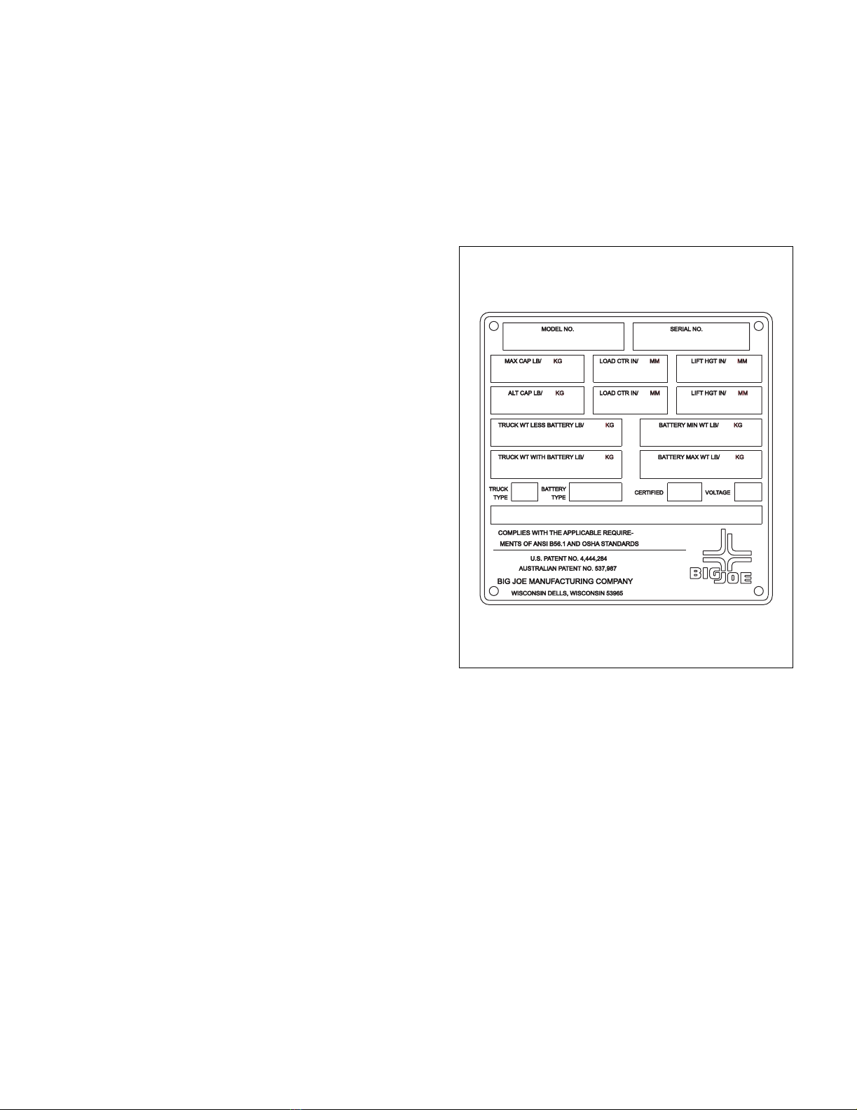
The model number will be found on the (Figure 1-1)
along with the serial number, lifting capacity, and load
center.
1-2. GENERAL DESCRIPTION.
Maximum load for personnel, merchandise and equip-
ment is 650 lounds.
The forward and reverse motion is controlled by the
speed controller switch in the control head. Stopping
and turning is controlled by the steering arm. Lift and
Lower is controlled by a control box attached to the
platform.
The battery-powered lift truck is quiet and without
exhaust fumes.
The reversible DC motor propels the lift truck in for-
ward and reverse direction throughout the available
speed range. The lift truck can ony be driven with plat-
form lowered. Drive is cutout when the platform is
raised above a preset limit.
Figure 1-1 Name Plate
R6209

1-2 901357
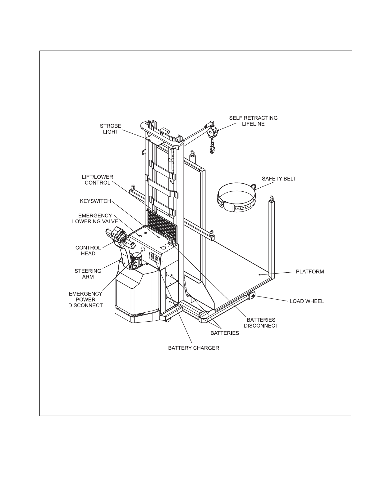
1-3. SAFETY FEATURES.
The PDBB-20-T12 is designed and engineered to pro-
vide maximum safety for operator and payload. Some
of the safety features incorporated into the design are:
• A platform surrounded by a chain and equipped with
a safety belt and self-retracting lifeline for operator
safety while the platform is in the raised position.
• Dead-man brake to apply mechanical brake and cut
off drive power when the steering arm is released.
• Belly-button switch to reverse truck should the oper-
ator accidentally pin himself against a wall or
obstruction when backing up.
• Travel disconnect switch to restrict movement when
platform is raised above the preset limit.
• All control functions automatically return to “OFF”
when released.
• Externally accessible quick-disconnect battery plug
and an emergency power disconnect within opera-
tor's reach.
• Separately fused control circuits and power circuits.
• Readily accessible HORN button.
• A lowering buzzer to provide audible alert that the
platfrom is being lowered.
• Pressure compensated flow control valve regulates
maximum lowering speed within prescribed limits.
• An emergency lowering valve provides a means of
manually lowering the operator.
• High visibility color scheme of truck and the strobe
light provide visual alert of the trucks presence.
• A keyswitch toguard against unauthorized operation.
901357 1-3
Figure 1-2 PDBB-20-T12 LIFT TRUCK
R6214

1-4 901357
NOTES

901357 2-1
SECTION 2
OPERATION
2-1. GENERAL.
This section gives detailed operating instructions for
the PDBB-20-T12 lift truck. The instructions are
divided into the various phases of operations, such as
operating the lift, driving, and stopping. Routine pre-
cautions are included for safe operation.
2-2. OPERATING PRECAUTIONS.
WARNING: Improper operation of the lift truck may
result in operator injury, or load and/or lift
truck damage. Observe the following
precautions when operating the
PDBB-20-T12 lift truck.
The following safety precautions must be adhered to
at all times.
• All warnings and instructions must be read and
understood before using the equipment.
• Equipment must not be altered in any way.
• Equipment must be inspected by a qualified person
on a regular basis.
• Be certain that required restraining means such as
safety belts, lifelines, and chains are properly used.
• Safety belt buckles must be visually inspected to
assure proper and secure connection before use.
• The self retracting lifeline should be attached to the
back Dee ring only on the safety belt.
• Replace any safety belt or life line that sustains per-
manent deformation or is otherwise damaged.
• Be certain that the lifting mechanism is operating
smoothly throughout its entire lift height, both empty
and loaded.
• Be sure that mast is vertical--do not operate on a
side slope.
• Be sure the platform is not tilted forward or rearward
when elevated.
• Be sure the truck has a firm and level footing.
• Before personnel are elevated, mark area with
cones or other devices to warn of work by elevated
personnel.
• Avoid overhead wires and obstructions.
• Personnel are to remain on the platform floor. Use of
railings, planks, ladders, etc., on the platform for pur-
pose of achieving additional reach or height is pro-
hibited.
• Personnel and equipment on the platform must not
exceed the available space.
• Lower platform to floor level for personnel to enter
and exit. Do not climb on any part of the truck in
attempting to enter and exit.
• When traveling, always lower the load as far as pos-
sible.
• Observe applicable traffic regulations. Yield right of
way to pedestrians. Slow down and sound horn at
cross aisles and wherever vision is obstructed.
• Operate truck only from designated operating posi-
tion. Never place any part of your body between the
mast uprights. Do not carry passengers.
2-3. BEFORE OPERATION
Table 2-1 covers important inspection points on
PDBB-20-T12 lift truck which should be checked prior
to operation. Depending on use, some trucks may
require additional checks.
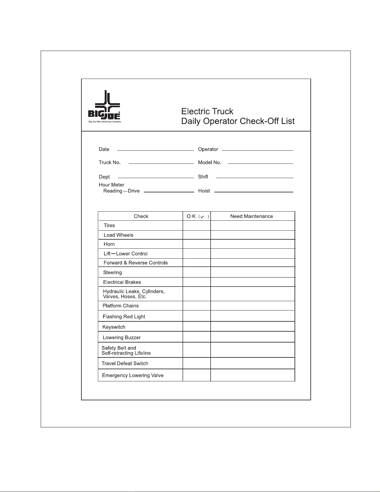
Figure 2-1 shows a sample format for a Operator
Checklist, which can be modified as necessary to fit
your operation.
WARNING: Periodic maintenance of this truck by a
QUALIFIED TECHNICIAN is required.
CAUTION: A QUALIFIED SERVICE TECHNICIAN
should check the truck monthly for
proper lubrication, proper fluid levels,
brake maintenance, motor maintenance
and other areas specified in the SEC-
TION 3.
WARNING: If the truck is found to be unsafe and in
need of repair, or contributes to an
unsafe condition, report it immediately to
the designated authority. Do not operate
it until it has been restored to a safe
operating condition. Do not make any
unauthorized repairs or adjustments. All
service must be performed by a qualified
maintenance technician.

2-2 901357
Table 2-1 Operator Checks
ITEM PROCEDURE
Platform chains Verify that platform chains are
present and functional.
Flashing red light Verify that the flashing red light
operates when the keyswitch is
engaged.
Lowering buzzer Verify that buzzer sounds when
the DOWN button on the plat-
form is pressed.
Safety belt and
lifeline
Verify that the safety belt and
self-retracting lifeline are
present, installed with locking
carabiner (when applicable),
and functioning properly.
Transmissionand
hydraulic sys-
tems.
Check for signs of fluid leakage.
Chains, cables
and hoses
Check that they are in place,
secured correctly, functioning
properly and free of binding or
damage.
Guards Check that safety guards are in
place, properly secured and not
damaged.
Safety signs Check that warning labels,
nameplate, etc., are in good
condition and legible.
Horn Check that horn sounds when
operated.
Steering Check for binding or looseness in
steering arm when steering.
Travel controls Check that speed controls on
control handle operate in all
speed ranges in forward and
reverse and that belly button
switch functions.
Wheels Check drive wheel for cracks or
damage. Move truck to check
load for freedom of rotation.
Hydraulic
controls
Check operation of lift and lower
to their maximum positions.
Brakes Check that brakes actuate when
steering arm is raised to upright
position, and when lowered to
horizontal position.
Deadman/
Parking brake
Check that steering arm raises to
upright position when released
and brake applies.
Battery discon-
nect
Check that battery can be
disconnected and recon-
nected. Check for connector
damage.
Drive limit switch Allow for enough space to oper-
ate truck in high speed. Elevate
forks approximately two feet,
then test drive truck to check if
drive is cut out.
ITEM PROCEDURE
901357 2-3
Figure 2-1 Sample of Operator Check List
R6201
2-4 901357
2-4. POWER DRIVE CONTROL HANDLE.
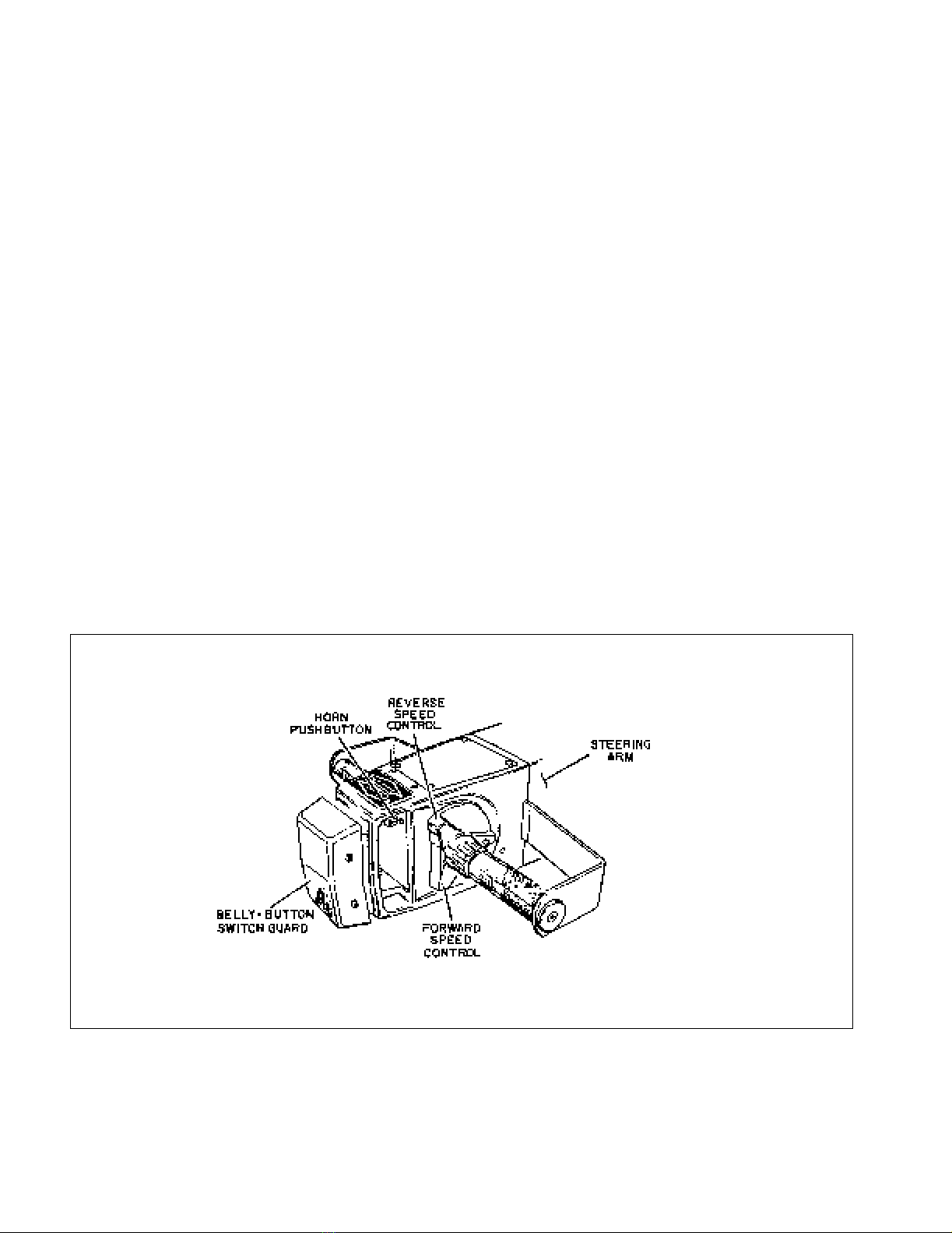
2-4.1. Control Handle.
Two triangular shaped speed controls provide for easy
thumb actuation. Controls include an infinitely variable
forward and reverse speed control, a belly-button
reversing switch, and a horn. See Figure 2-2.
2-4.2. Steering Arm Controls.
Lowering the steering arm to the horizontal or raising
to the vertical applies the brake (See Figure 2-3). All
traction control power is shut off when the brake is
engaged. When the steering arm is in the upright posi-
tion, the brake acts as a parking brake. Deadman
braking occurs when the handle is released and spring
action raises it to the vertical position.
When the lower portion of the triangular speed control
knob is pressed forward, contacts are closed for first
speed in the forward direction. Pressing the speed
control farther closes a contact for second speed and
farther, third speed. Pressing the upper portion of the
speed control governs the three reverse speeds in the
same manner.
2-4.3. Driving and Stopping Procedures.
The following procedure describes driving and stop-
ping the PDBB-20-T12 lift truck.
1. Turn the key switch to the on position.
2. Grasp the grips of the steering arm so that the
speed control can be comfortably operated by the
thumbs.
3. Lower the steering arm to a comfortable position
above horizontal to disengage the brake and to
energize the electrical circuits.
4. To move forward, slowly press the lower portion of
the speed control. Press the forward speed con-
trol farther to increase speed.
5. To stop, release the speed control and lower the
steering arm to the horizontal position. In this
position, the electrical brake activates.
The brake may also be applied by raising the
steering arm to the upright position.
6. To travel in reverse, lower the steering arm to a
comfortable position and slowly press the upper
portion of the speed control.
NOTE: Acceleration in reverse is the same as in the
forward direction.
Figure 2-2 Control Handle
R6202

901357 2-5
Figure 2-3 Steering Arm Braking Position
2-5. BELLY-BUTTON SWITCH GUARD.
The belly-button switch guard minimizes the possibility
of the driver being pinned by the steering arm while
driving the lift truck in reverse. If the guard presses
against the driver while the lift truck is being driven in
reverse, the guard actuates a switch which changes
the direction of the lift truck to forward direction in low
speed.
2-6. STEERING ARM RETURN SPRING.
The steering arm return spring automatically raises the
steering arm to the upright position when the steering
arm is released. If the steering arm snaps up abruptly,
or does not return fully, the steering arm return spring
requires adjustment. Return truck to maintenance
group for adjustment.
2-7. LIFT/LOWER/STOP CONTROL.
The LIFT/LOWER/STOP pushbuttons on the platform
are used raise and lower the platform at a fixed rate of
speed.
Proceed as follows to raise and lower the platform.
1. If truck is equipped with a key switch, turn it to the
on position.
WARNING: Check the space above the mast and the
load to be sure that there is sufficient
room for raising the platform. Make sure
the load is centered and does not
exceed capacity.
1. To raise the platform, push in the LIFT button and
hold until lift carriage reaches desired lift height.
2. To lower the forks, push in and hold the LOWER
button until platform is at the desired height.
2-1. PARKING.
When finished with moving loads, drive truck to its
maintenance or storage area. Disconnect batteries
from TRUCK receptacle and connect to CHARGER
receptacle. Charge batteries as necessary. Refer to
battery care instructions, paragraph 3-3.
R6203

2-6 901357
NOTES

901357 3-1
SECTION 3
PLANNED MAINTENANCE
3-1. GENERAL.
Planned maintenance consists of periodic visual and
operational checks, parts inspection, lubrication, and
scheduled maintenance designed to prevent or dis-
cover malfunctions and defective parts. The operator
performs the checks in SECTION 2, and refers any
required servicing to a qualified maintenance techni-
cian who performs the scheduled maintenance and
any required servicing.
3-2. MONTHLY AND QUARTERLY CHECKS.
Table 3-1 is a monthly and quarterly inspection and
service chart based on normal usage of equipment
eight hours per day, five days per week. If the lift truck
is used in excess of forty hours per week, the fre-
quency of inspection and service should be increased
accordingly. These procedures must be performed by
a qualified service technician or your Big Joe service
representative.
3-3. GEL CELL BATTERY CARE.
3-3.1. General.
These Gel Cell Batteries are maintenance-free. Any
attempt to open the battery will void the warranty.
Ultra-deep discharging of brand new batteries
should be avoided for at least 15 cycles. To dramat-
ically extend battery life, ultra-deep discharge should
be avoided. The shallower the average discharge, the
longer the battery life.
3-3.2. Charging Batteries
Charging requirements will vary depending on depth of
discharge and temperature. Follow safety rules when
placing a battery on charge.
Proceed as follows:
1. Park truck at charging station with platform low-
ered and key switch off.
2. Check the condition of the AC cord, the battery
connector and battery cables. If there are any cuts
in the cable, any exposed wires, loose plugs or
connectors, DO NOT attempt to charge the bat-
teries. Contact appropriate personnel for repairs
to be made.
3. Serial Number 375067 to 380099: Disconnect
the batteries from the truck and connect batteries
to the charger. Make sure connectors are mated
properly.
Serial Number 38100 and Higher: There is no
need to switch the battery connector. An AC
charging relay is used.
4. Connect the AC cord to the truck and then plug
into the 120 VAC power supply.
Table 3-1 Monthly and Quarterly Inspection and Service Chart
VISUAL CHECKS
INTERVAL INSPECTION OR SERVICE
Monthly Check drive motor for proper operation
Monthly Check pump motor for proper operation
Monthly Check electrical brake for proper operation
Monthly Check load wheels for wear
Monthly Check drive wheel for wear
Monthly Inspect wiring for loose connections and damaged insulation
Monthly Inspect contactor tips for excessive pitting and wear
Monthly Check deadman brake switch for proper operation
Monthly Check lift chain tension, lubrication & operation (See paragraph 3-5.)
Quarterly Check lift cylinder wiper ring and packing for leakage
Quarterly Check for excessive jerking of steering arm when stopping or starting
Semi-annually Replace hydraulic filter assembly
Semi-annually Inspect for chain wear (See paragraph 8-2.)

3-2 901357
5. The battery charger is fully automatic and will
cycle automatically (depending on amount of
charge needed). Charge status can be observed
as follows (Refer to Figure 3-1):
a. The top three LED’s indicate charger status.
At start of charge the RED (Charge) LED will
be ON indicating the batteries are connected
and charging. After the batteries charge to
approximately 80% the Yellow LED comes
ON. After a time (1 hour minimum) the Green
LED comes ON indicating battery ready.
NOTE: The battery charger includes an override
timer which terminates the charge if the cycle
does not complete after 18 hours of charging.
This time-out condition is indicated by the
green LED flashing off and on, and it indi-
cates a fault condition which should be inves-
tigated. This will occur if the charger cannot
raise the battery voltage to the preset voltage
limit. Possible causes indicate a battery fault,
a charger fault, low AC power supply voltage,
or excessive discharge. The override timer
can be reset by switching the AC power to the
charger off.
b. The lower four red LED’s indicate current
flow. Normally at start of charge, if the batter-
ies are discharged, all four red LEDs will be
on indicating maximum 25A charge current.
As the batteries charge the current drops and
the LEDs go OFF as the current drops to
20A, 15A, 10A and 5A respectively.
Figure 3-1 Charge Indicator

901357 3-3
3-3.3. Removing Batteries from Charger
1. The Green “READY“ LED stays on until the
charger is unplugged from AC outlet.
2. Disconnect AC plug from the power supply and
then remove it from the truck.
3. Disconnect the batteries from the charger and
connect the batteries to the truck. Make sure con-
nectors are mated properly.
3-4. LUBRICATION.
Refer to Table 3-2 for the recommended types of
grease and oil. Table 3-4 identifies the items requiring
lubrication.
3-5. LIFT CHAIN MAINTENANCE.
Fully raise and lower platform while observing chains
as they move over all chain sheaves. Ensure chain is
aligned and tracking properly and all links are pivoting
freely. With platform fully lowered, spray or brush on a
film of SAE 30 or 40 engine oil.
Table 3-2 Recommended Lubricants
(See Table 3-4 for Application)
No. 1 Transmission oil—EP SAE 80W-90
No. 2 Grease—Lithium base, general purpose.
No. 3 Hydraulic oil-Heavy duty with a viscosity of
150 SUS (in temperatures below 32°F
use 100 SUS) foam suppressing agent
and rust and oxidation inhibitors.
Big Joe Part No.900855 (1 gallon)
900893 (1 quart)
No. 4 SAE 30 or 40 Engine lubricating oil

3-4 901357
Table 3-3 Lubrication Diagram
Table 3-4 Lubrication Chart
FIG 3-3
INDEX
NO.
LOCATION METHOD OF
APPLICATION
TYPE
(Table
3-3)
APPLICATION
OF
LUBRICANT
1 Hydraulic System
Capacity-6 quarts
— No. 3 With lift carriage fully lowered, fill
reservoir with hydraulic oil to
"FULL" mark on dip stick.
2 Platform rollers Gun No. 2 Pressure lubricate.
3 Load Wheels Gun No. 2 Pressure lubricate.
4 Mast rollers Gun No. 2 Use point adapter for Female
grease fitting.
5 Outer and inner mast Brush No. 2 Full length of channel where rollers
operate
6 Ram head sheaves Gun No. 2 Pressure lubricate.
7 Transmission
Capacity 4 1/2 pints
Can No. 1 Fill to Hex plug (Fill level plug)
level. Remove vent and fill
through vent hole.
8 Steering arm elbow Can No. 4 1 or 2 drops each time serviced.
9 Lift Chains Brush or Spray No. 4 See Paragraph 3-5.
R6215
Table of contents
Other Big Joe Truck manuals


 Operator's manual")


