Merloni Elettrodomestici 85510 Operating and installation instructions

Merloni Elettrodomestici UK Ltd
© 2004 Reg. Office: Peterborough PE2 9JB Registered in London: 106725
Service
Information
CREDA
RF PANEL
HEATERS
Models Covered:
400 mm High
85510 (800W) RF/E408
85520 (1000W)RF/E410
85530 (1200W)RF/E412
85540 (1500W)RF/E415
85550 (2000W)RF/E420
200 mm High
85610 (800W) RF/E208
85620 (1000W)RF/E210
85630 (1200W)RF/E212
85640 (1500W)RF/E215
400 mm High - IP24
85820 (600W) RF/E406S
85840 (1000W)RF/E410S
5411760 Issue 1 Feb. 2004

2
SAFETY NOTES & GENERAL SERVICING ADVICE
1.This Manual is NOT intended as a comprehensive repair/maintenance guide to the appliance.
It should ONLY be used by suitably qualified persons having technical competence, applicable
product knowledge, and suitable tools and tests equipment.
2. If you are in the slightest doubt we strongly recommend that you contact your installer or contact
Applied Energy Products Ltd. - Technical Help Desk (Tel. 08709 000430).
3. For all other customers, consult your local distributor or other authorised service agent.
4. Earth Continuity and Insulation Resistance checks must precede servicing.
5. The heater must be connected to fixed wiring via a double pole isolating switch having a
contact separation of 3 mm in each pole and in accordance with I.E.E. regulations
currently in force and in accordance with any local code of practice.
6. It can be dangerous to attempt 'DIY' repairs/maintenance on complex equipment and the
Company recommends that any problem with the appliance is referred to its own Service
Organisation.
7. WARNING:
ALWAYS ISOLATE THE HEATER FROM THE ELECTRICAL SUPPLY/SUPPLIES before
undertaking any maintenance work. As the heater may have more that one electrical feed to the unit,
it is essential to ensure that all electrical supplies are isolated from the heater.
8. Personal safety precautions must be taken to protect against accidents caused by sharp edges on
metal and plastic parts.
9. Genuine Creda spare parts should always be used.
10. The mains lead is specially produced by Creda. In the event of damage, a replacement should be
ordered from Creda and installed by a qualified electrician. We therefore strongly recommend that
you contact your installer or Applied Energy Products Ltd. - Technical Help Desk (Tel.: 08709
000430).
11. WARNING:
The surface temperatures of this heater are within the requirements of the EU directives. However,
the temperatures are sufficiently high to cause scald injury to bare flesh. Aged or infirm persons or
young children should not be left unsupervised in the vicinity of the heater, unless a suitable guard is
fitted.
12. The heater should not be mounted directly below an electric outlet.
13. Vinyl floor coverings and varnished floors require a minimum clearance of 120 mm to the underside
of the heater.
14. After servicing the appliance must be rechecked for electrical safety.
Originator - E. Arnold, Service Technical Engineer

3
INDEX
Safety Notes & General Servicing Advice . . . . . . . . . . . . . . . . . . . . . . . . . . . . . . . . . 2
Introduction . . . . . . . . . . . . . . . . . . . . . . . . . . . . . . . . . . . . . . . . . . . . . . . . . . . . . . . . . . 3
Technical Specification . . . . . . . . . . . . . . . . . . . . . . . . . . . . . . . . . . . . . . . . . . . . . 4 - 5
Safety in Use . . . . . . . . . . . . . . . . . . . . . . . . . . . . . . . . . . . . . . . . . . . . . . . . . . . . . . . . . 5
Installation . . . . . . . . . . . . . . . . . . . . . . . . . . . . . . . . . . . . . . . . . . . . . . . . . . . . . . . . 6 - 7
Wiring Diagram . . . . . . . . . . . . . . . . . . . . . . . . . . . . . . . . . . . . . . . . . . . . . . . . . . . . . . . 7
Setting The Controls. . . . . . . . . . . . . . . . . . . . . . . . . . . . . . . . . . . . . . . . . . . . . . . . . . . 8
CredaSaver . . . . . . . . . . . . . . . . . . . . . . . . . . . . . . . . . . . . . . . . . . . . . . . . . . . . . . 9 - 11
RF Receiver . . . . . . . . . . . . . . . . . . . . . . . . . . . . . . . . . . . . . . . . . . . . . . . . . . . . . . . . . 12
Installing & Setting the Credazone Controller . . . . . . . . . . . . . . . . . . . . . . . . . 13 - 16
Quick Reference Chart for Fault Diagnosis . . . . . . . . . . . . . . . . . . . . . . . . . . . . . . . 17
Dismantling Procedure. . . . . . . . . . . . . . . . . . . . . . . . . . . . . . . . . . . . . . . . . . . . 18 - 19
INTRODUCTION
These heaters were introduced into the Creda range in September 2001 and have a 1 year
guarantee period.
The servicing period of these products began in March 2003.
All Panels are electric Panel Convectors with integral adjustable thermostats.
The thumb wheel thermostats are adjustable between 5°C to 30°C and positioned on the top right
side facia. These thermostatic heaters can also be controlled by a remote non-wire radio frequency
transmitter (CredaZone1 or 4) with the Receiver or plug-in (85711).
A timer control plug-in (85712) is also available.
All panels include a double pole on/off switch, with a contact separation gap of 3 mm situated on the
lower right hand side of the heater and an electrical 4 core cable is fitted as standard.
Position of Rating Plate
The Rating Plate is positioned on the top right hand side of the heater, immediately behind the
’Do Not Cover’ legend.
4
TECHNICAL SPECIFICATION
Weekly programmable
A single CredaZone controller can control several RF Panels
Radio communication 433 MHz
Range 35m (free sight)
Meets requirements of the EUs low voltage directive (73/23EEC) and directive concerning
electromagnetic compatibility (89/31/EEC).
Thermostatic control
Frost protection 5 - 15°C
Setback temperature 5 - 30°C
Comfort temperature 5 - 30°C
* Splash proof version suitable for use in bathrooms. IP24C. Incorporates a slash proof cover with
Manual reset.
CONTROLLERS
Model
No. Code Rating
(W)
Supply
Single
Phase AC
Current
(amps) Width
(mm) Height
(mm) Depth
(mm)
Fixing
Centres
(mm) Other
85510 RF/E408 800 230-240V 3.5 645 400 80 370
85520 RF/E410 1000 230-240V 4.3 735 400 80 460
85530 RF/E412 1200 230-240V 5.4 915 400 80 640
85540 RF/E415 1500 230-240V 6.5 1095 400 80 820
85550 RF/E420 2000 230-240V 8.7 1365 400 80 1090
85610 RF/E208 800 230-240V 3.5 1095 200 80 820
85620 RF/E210 1000 230-240V 4.3 1275 200 80 1000
85630 RF/E212 1200 230-240V 5.4 1545 200 80 1270
85640 RF/E215 1500 230-240V 6.5 1725 200 80 1450
85820 RF/E406S 600 230-240V 2.6 555 400 80 280 *
85840 RF/E410S 1000 230-240V 4.3 735 400 80 460 *
Model No. Description Method
85710 CredaZone 4 RF Controller Hand held / Wall Mounting
85711 Plug-in Receiver Plug-in
85712 Plug-in Creda Saver Plug-in
85715 CredaZone 1 RF Controller Hand held / Wall Mounting
85713 Covers for Controls

5
OPTIONAL CONTROLLERS (Not supplied)
• CredaZone 1 or 4
Remote controller requires 3 x AAA 1.5V alkaline batteries. (Battery lifetime 2 years.)
Hand held or wall mounted.
Note: - Requires CredaZone Receivers.
• CredaZone Receiver
Plug-in cartridge with integral thermostat back-up.
Note: - Requires CredaZone 1 or 4 Controllers.
• Creda Saver
Plug-in pre-programme cartridge.
15 preset programmes which can be adjusted to suit (Day/Hour).
Economy mode thermostat on Creda Saver.
•Covers
Cover to prevent unwanted heater operation.
This is in 2 parts for the thermostat knob and the on/off switch (Contact supplier).
SAFETY IN USE
DO NOT spill liquids onto the appliance. If you do, switch the heater OFF and get a qualified
electrician to check it.
When young children, elderly or infirm people are present, the appliance should be adequately
guarded.
DO NOT poke objects through the grille ventilation slots or any other apertures in the heater casing.
DO NOT use polishes on the heater or on furniture near to it.
If you are the householder, DO NOT attempt to repair it yourself. In case of breakdown or other
failure, switch off the heater at the wall switch and consult your supplier, local electricity supplier or
Applied Energy Products Ltd. Always ensure that the heater is switched off at the wall switch and
the fuse removed before any repair is carried out.
The mains lead is specially produced by Creda. In the event of damage, a replacement should be
ordered from Creda and installed by a qualified electrician.

6
INSTALLATION
Before drilling walls to fit the wall brackets, check that there are no cables or pipes buried in the wall.
Wall fixings must be appropriate for the construction of the wall.
The heater should be mounted horizontally and not be mounted directly below an electric outlet.
Position the heater to avoid curtains etc. being within 100 mm (4”) around the top and ends of the
heater. Vinyl floor coverings and varnished floors require a minimum clearance of 120 mm to the
underside of the heater.
Heater types 85820 and 85840 are suitable for use in bathrooms or shower rooms.
For these installations the heater must be positioned so that a person in the bath or shower cannot
touch switches and other controls.
Ensure that all packaging material is removed from the heater.
1. Fix the wall bracket to the wall, allowing for the minimum clearance requirement (listed in the
tables below). The wall bracket may also serve as a template (see drawing). Please ensure the
wall bracket(s) is positioned in accordance with the drawing.
2. Align the bottom of the heater onto the bottom hooks of the wall bracket. Raise the heater
towards an upright position and secure the wall bracket safety strap(s), before finally securing
the heater to the top wall brackets.
Cat. No. Watts L A
85610 800W 1095 820
85620 1000W 1275 1000
85630 1200W 1545 1270
85640 1500W 1725 1450
Cat.No Watts L A
85510 800W 645 370
85520 1000W 735 460
85530 1200W 915 640
85540 1500W 1095 820
85550 2000W 1365 1090
Cat.No Watts L A
85820 600W 555 280
85840 1000W 735 460
Fig. 1
Mounting Positions
7
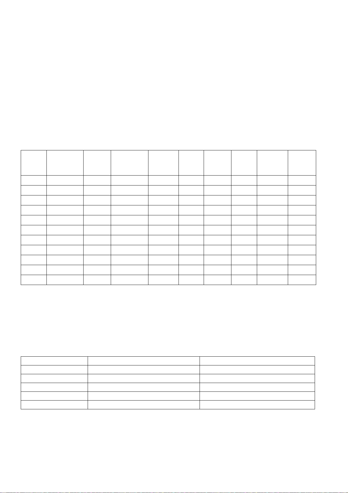
CONNECTING THE HEATER TO THE MAINS
All heaters incorporate a 4 core mains cable.
The heater must be connected to fixed wiring via a double pole isolating switch having a contact
separation of 3 mm in each pole and in accordance with I.E.E. regulations currently in force and in
accordance with any local code of practice.
GREEN & YELLOW EARTH
BLUE NEUTRAL
BROWN LIVE
BLACK CONTROL CABLE LIVE (Pilot Wire)
Note: - The Live Black Pilot wire allows a 5° night set-back which can be controlled by a remote
timer and must be disconnected before service.
If the Night Set Back Control is not required, the Black control cable can be ignored, however, the
cable must be made safe within the appliance. Refer to Night Set Back Control below.
NIGHT SET BACK CONTROL
The heater has an in-built temperature reduction function that is designed to be controlled by a
remote central controller (time switch). When the controller sends a signal (230 - 240V applied) via
the control cable, the thermostat will reduce the room temperature by approximately 4°C in relation
to the set temperature.
SCHEMATIC WIRING DIAGRAM
Fig. 2
8
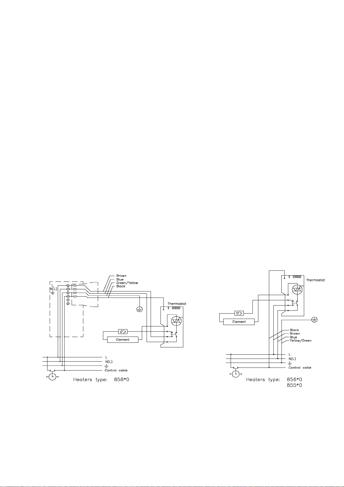
SETTING THE CONTROLS
Ensure that the appliance is securely fixed to the wall with the correct electrical connections made.
Switch on the heater by pressing the switch A, and turn the thermostat dial (B) to 30 (max.).
Red LED Cshould come on, indicating that the heater is on and working. When the required room
temperature is reached, slowly turn the thermostat dial Bbackwards from the 30 until the light C
goes out. The minimum setting 5 offers frost protection.
Warning - the surface of the heater can be hot
Commissioning Period
NOTE! The internal element(s) have a protective oil covering. This will evaporate when the heater is
switched on for the first time and may emit a harmless smoke for the first few minutes.
Rooms must be well ventilated during the commissioning period.
SAFETY DEVICE
The heater has a built-in safety device, which disconnects the power, if for example, the heater is
accidentally covered. The item(s) covering the heater must be immediately removed!
NOTE: The safety device will automatically reconnect the power supply as soon as the temperature
in the heater returns to normal (excluding 85820 and 85840).
Heater models 85820 and 85840 have an integral manual re-set cut-out.
As soon as the temperature in the heater returns to normal, lift and tilt the heater forward and press
the red button on the rear of the heater. The electrical supply will be restored to the heater.
Fig. 4
Red
Light
Green
Light
Light
Antenna Button
Fig. 3
Heater Controls
Creda Zone Receiver

9
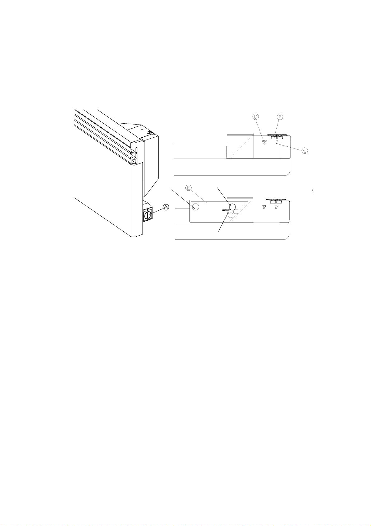
CREDASAVER
CREDA PLUG-IN CONTROL MODULE (Optional)
C = Mode Button
D = Set / Pause Button
E = Display
F = Selected Mode Indicators
G = Thermostat Knob
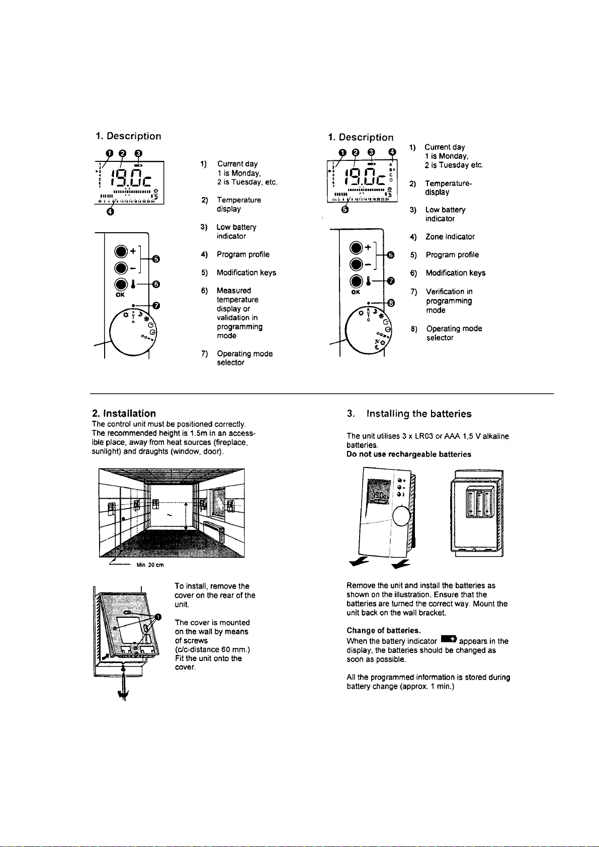
1. Description
The CREDASAVER is a timed control, which can be plugged into all Creda thermostat heaters,
type 85**0.
It gives you the ability to control the heater with up to 15 pre-defined programmes.
In the Comfort Mode, the heater will be regulated according to the temperature chosen with
the heater thermostat knob indicated by red light (C) Fig. 3.
In the Economy Mode, the temperature will be regulated according to the position of the
thermostat knob (located on the side) on the CREDASAVER plug-in unit.
When in the Economy Mode, the Green LED (D) Fig. 3 on the heater will be on.
Note: - For the controller to operate you MUST programme the present date and time.
2. Installation
1. Switch off the heater.
2. Plug-in the CREDASAVER into the left-hand side of the thermostat housing.
3. Adjust the thermostat knob (B) Fig. 3 on the heater to the desired comfort temperature.
4. Adjust the thermostat knob (G) Fig. 5 on the CREDASAVER to the desired Setback
Temperature.
5. Switch on the heater. Wait until the display (E) Fig. 5 appears with two horizontal lines.
When installed for the first time or after a prolonged period of power failure, the Creda Saver will
lose its settings. This is indicated by the display (E) Fig. 5 showing two horizontal lines.
3. Choice of Programme & Adjustment of Hour / Day
This is done by means of the two keys on the CREDASAVER.
The MODE-key (C) Fig. 5 is used for choosing adjustment mode, e.g Programme Day, Hour
and Minutes.
The SET/PAUSE- key (D) Fig. 5 is used for altering the settings within each mode.
4. To Start
1. Press the MODE key once. The PROG red LED (F) Fig. 5 will light up with the first programme
'P0'.
2. Choose a programme by pressing the SET/PAUSE key until the desired programme comes up.
FECD
G
Fig. 5
Credasaver
Module
10
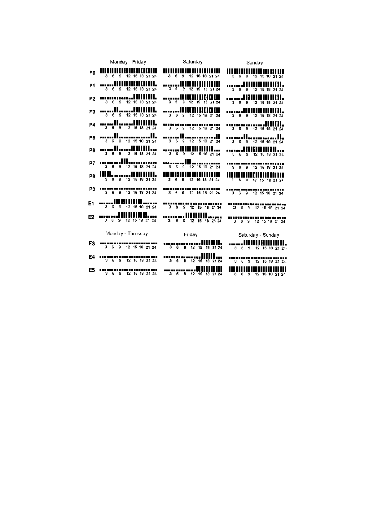
3. The 15 defined pre-programmes will be indicated as P0, P1, ....,P9, E1, E2, ...., E5 in the
display. Refer to the programme chart below and select one pre-programmed to suit the end
user.
4. Press the MODE key once more. The DAY (F) LED will light up and indicate that a weekday
may be chosen.
5. Press the SET/PAUSE key to choose one of the pre-programme profiles for the weekday.
1 is Monday, 2 is Tuesday,., 7 is Sunday.
6. Press the MODE key once more, and the LED marked HOUR will light up. The correct hour
may be chosen.
7. Press the MODE key once more. Now the LED marked MIN will light up, and the minutes can
be adjusted.
8. After approximately 20 seconds the CREDASAVER returns to its normal operating mode and
all settings are stored.
5. Cancellation of Setback Period
1. A setback period can be cancelled by pressing the SET/PAUSE key when the CREDASAVER
is in its normal operating mode.
NOTE: - In the normal operating mode, none of the 5 red LEDs will be illuminated.
The present or first setback period will then be cancelled. To suspend the cancellation, the
SET/PAUSE key may be pressed once more.
CREDASAVER QUICK PROGRAMME GUIDE
PRESS ONCE
WAIT 20 SECONDSPROG. SAVED
Fig. 6
Quick Setting Guide - Credasaver
11
PROGRAMME HEATING PROFILES
Fig. 7

12
RF RECEIVER
CREDAZONE PLUG-IN CONTROL MODULE
1. Description
The following RF Receiver plug-in module will operate Creda Panel heater types 855*0, 856*0
and 858*0 with thermostat control and must be controlled by one of the following central
controllers: - CredaZone 1 or CredaZone 4.
2. RF Receiver First Time Installation
a. Switch the heater off.
b. Insert the RF Receiver into the left hand side of the
thermostat on the upper right hand side of the heater.
c. Set the thermostat wheel (B) to the to desired
temperature.
NOTE: - Should the RF Receiver fail the desired
temperature will be maintained.
d. Switch on the heater.
e. After a few seconds, the RF Receiver CONNECT (L) LED will light continuously.
f. Set the central unit (CredaZone1 or CredaZone4) to its configuration mode.
g. Press and hold the '+' button for 3 to 5 seconds and the configuration mode CnF will be
displayed.
h. Press RF Receiver '+' button again until the CnF display is replaced by '- - -'.
i. The selected configuration will only begin when the Auto position is selected.
3. Testing for Correct Configuration
a. Set the central unit controller CredaZone1 or CredaZone 4) to the configuration mode .
b. From the '- - -' display, press the - (minus) button on the CredaZone controller until the script
'tEst' is displayed.
c. At this stage the RF Receiver will begin with 3 flashes for every 3 seconds.
d. Press the CredaZone controller - (minus) button to display '- - -'.
e. Switch the CredaZone controller to the Auto select position.
f. The test procedure is now complete and the Credazone controller will now control the heater.
Note: - In the case of electrical power failure it will be necessary to reconfigure all RF
Receivers.
Reconfiguration
1. Set the central unit controller (CredaZone1 or CredaZone4) to the configuration mode .
2. Press the button (M) on the RF Receiver and hold it for approximately 10 seconds until the
CONNECT LED starts flashing.
3. Press the key once more and after a few seconds it will light continuously.
4. Close the configuration mode on the central CredaZone1 or CredaZone4 unit to Auto.
5. The CredaZone1 or 4 central unit will now control the heater.
Notes:
During normal operation the CredaZone central unit will control the heater.
Should the radio communication fail, the RF Receiver will switch to the room temperature
indicated by the thermostat wheel (B). In this case the CONNECT LED will start flashing.
When the radio communication is restored, the central controller will automatically start
operating again.
LM
Fig. 8
13
INSTALLING & SETTING THE CREDAZONE CONTROLLER
The following information is taken from the user instructions for the controller.
CredaZone1 CredaZone4

14
CLOCK SETTING THE CREDAZONE1 & CREDAZONE4
Press the key and the value of the room temperature is displayed.
CLOCK ADJUSTMENT
Remember: 1 = Monday; 2 = Tuesday; ....... 7 = Sunday
CONGIFURATION CREDAZONE1
Note: -
Before the system can be controlled by the CredaZone, all Creda RF Receivers MUST first be
configured. Refer to RF Receiver First Time Installation and Configuration.
• Should more than one controller be used, the configuring decides which receiver is to be
controlled by which control unit.
• Take the CredaZone controller to each heater or ensure the controller is within range of the
heaters and begin configuring each heater.
• Set the controller (CredaZone1 or CredaZone4) to the configuration mode .
• Press and hold the + button for 3 to 5 seconds until the configuration mode CnF is displayed.
• Press the RF Receiver + button again until the CnF display is replaced by '- -'.
• Set the CredaZone controller to the 'Auto' setting.
TEMPERATURE SETTINGS ON THE CREDAZONE1
Setting the Comfort Temperature
The Comfort temperature setting will be the temperature when the room is occupied.
The Comfort temperature setting ranges between 5°C and 30°C.
Set the Comfort temperature and record in the temperature box below.
* Insert temperature required.
Note:The Comfort temperature must be above the room temperature for the panel heater(s) to
switch on to the heating mode.
The CredaSaver Red neon will light to indicate when the RF Panel Heater is switched to the
heating mode.
By passing the 24.00 Hrs, the following day will display.
Quick pressing of the keys gives 1 minute steps.
Press and hold gives fast change.
*Temperature = °C

15
Setting Frost Protection Temperature
Setting the Set-Back Temperature

16
PROGRAMMING THE CREDAZONE CONTROLLER
Week Programming
17
QUICK REFERENCE CHART FOR FAULT DIAGNOSIS
Heater is cold Safety Cut-out operated
Thermostat or controller set too low
Heater switched off either at heater
switch, local isolator or consumer unit
Bad wiring connection
Supply failure
Reset
Adjust settings
Check and switch on
Check wiring
Check electrical supply
Poor heat output Settings on thermostat or controller.
Heating element failure
Faulty thermostat
Increase temperature settings
Check / replace
Check / replace
Two flashing
horizontal lines
appear on the Creda
Saver plug-in timer
When installed for the first time or after
a prolonged period of power failure,
the CREDASAVER will lose its
settings. This is indicated by the
display (E) showing to horizontal lines
Re-programme
CONNECT LED is
flashing on the
Receiver
Radio communication failure Check Creda Zone
controller / reset.
Ensure that the Receiver is
correctly inserted.
Creda Zone
controller battery
indicator is on
Faulty or missing batteries Check / replace
Safety cut-out
operated Clothing draped over heater
Restricted air circulation around heater
Faulty thermostat
Check and remove
obstructions

18
DISMANTLING PROCEDURE
ALWAYS ISOLATE THE HEATER FROM THE ELECTRICAL SUPPLY/SUPPLIES before
undertaking any maintenance work. As Tele-switching of off peak supplies becomes more common,
and the times at which off peak supplies are available varies, it is essential that the off peak
consumer unit as well as the adjacent isolator switch are both switched off prior to servicing the
heater.
A. FRONT PANEL
1. To remove the front panel, release the screws along the bottom edge of the front panel.
2. Pull the bottom edge of the front panel forwards and lift the top flange away from the top lip of
the rear cover. Put the front cover in a safe place to prevent damage.
B. HEATING ELEMENT
WARNING: - Allow the heater sufficient time to cool down before any attempt is made to remove
the element.
1. Release the Live and Neutral connections from each end of the straight length, heating
element.
2. Using suitable long nosed pliers bend back the 4 retaining tags at each end of the element.
3. Lift the element away from the heater.
4. Fit the new element, ensuring adequate electrical clearance between the terminals and the
outer casing and/or the PCB.
5. Straighten the 4 retaining tags to secure the element.
IMPORTANT: The retaining tags provide electrical bonding of the element sheath to the main Earth
connection. It is vital that these tags securely grip the element. After changing an element check the
resistance between the element sheath and the earth terminal. Resistance must be less than 0.5Ω.
6. Reconnect the cables to the element terminals. Ensure the push on connections securely grip
the element terminal pin.
7. Refit the front cover and the retaining screws. Ensure the screws are securely tightened as they
provide the earth bonding for the front panel.
C. WALL BRACKET
1. To replace the wall bracket, firstly lift the heater upwards, then pull the top of the unit away from
its location.
2. Release the white plastic restraining strap(s) from the rear of the heater and lift the complete
unit away from the bracket.
3. Remove the bracket from the wall.
4. Fit the new bracket securely to the wall.
5. Enter the heater on the hooks at the bottom of the wall bracket. Rise the heater towards an
upright position, fasten the strap(s) and fasten the heater on the top of the wall brackets.
D. OVERHEAT THERMOSTAT
WARNING: Allow the heater sufficient time to cool down, before any attempt is made to replace the
thermostat.
The heater must be isolated from the electricity supply before changing the thermostat.
1. Remove the front cover as described earlier.

19
2. Prise the 2 plastic, thermostat-securing lugs apart, and lift the thermostat from the plastic
bracket. Note the orientation of the thermostat to ensure new unit is fitted back in the same way.
3. Remove the 2 terminals from the old thermostat and fit the new unit in the same way.
If enhanced access is required the plastic housing can be removed by pulling the top edge
towards you, and twisting the housing anti-clockwise through 45°. The housing can now be
pulled from the heater.
4. Refitting is a reverse of the removal procedure.

20
For spare parts contact:
Applied Energy Products Ltd.
National Spares Line:
08700-102829
This manual suits for next models
10
Table of contents
Popular Heater manuals by other brands

Eastbrook
Eastbrook BERKELEY instruction manual

wibo
wibo Thermatic Clima Series instruction manual

Convair
Convair CTH02 Owner's instruction manual

Berko
Berko BDBSL Installation, operation & maintenance instructions

Master
Master 140TMHD-KFA User's manual & operating instructions

Leister
Leister LE 5000 DF operating instructions


CONVECTAIR
CONVECTAIR ALTO 7375 C Installation and operating instructions

Berko
Berko ASL3 Installation, operation & maintenance instructions

Jula
Jula 417-013 operating instructions

Ventair
Ventair Myka 4 Installation and warranty instructions

DeLonghi
DeLonghi HFX66V15C user manual

ShoreStation
ShoreStation CS24-108-7A owner's manual