Totai 16/DK1023A User manual
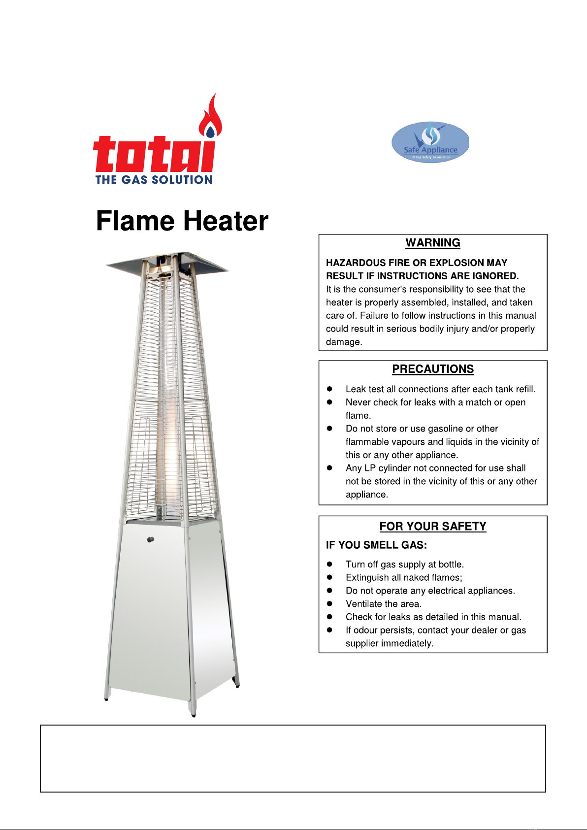
For Outdoor Use Only
Important: Read these instructions for use carefully so as to familiarise yourself with
the appliance before connecting it to its gas container. It is also important to follow the
assembly instructions. Keep these instructions for future reference
Model: 16/DK1023A
LPGSASA PERMIT NUMBER 1051-XX-RSA-12-A
INSTRUCTIONS FOR USE AND ASSEMBLY
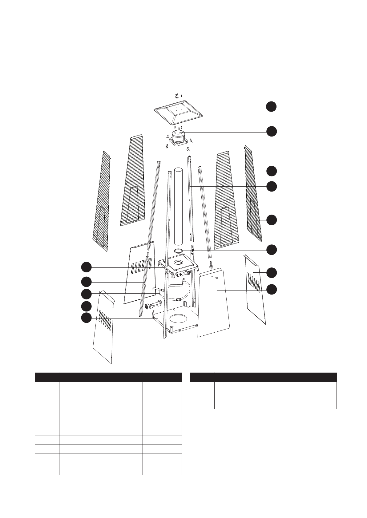
Parts List:
Reflector
Flame Screen
Glass Tube
Protective Guard
NOITPIRCSED TRAP QUANTITY
Flame Screen
1
L
M
N
Control Box Assy
Lower Support
Block Belt
4
1
1
1
Wheel Assembly
Bottom Plate
NOITPIRCSED TRAP QUANTITY
A
Reflector
1
B 1
C
Glass Tube
D
Upper Support
E
1
4
F
G
4
H
Black Silicone Ring
Protective Guard
Side Panel
J
Front Panel
K
1
3
1
A
B
C
Upper Support
Black Silicone Ring
D
E
Side Panel
F
G
Front Panel
H
Block Belt L
Lower Support K
Control Box Assy J
Wheel Assembly M
Bottom Plate N
Please check parts against the list below before assembling your Flame Heater. Take a few moments
to familiarise yourself with the contents. Check that all holes are clear of paint before assembly
ASSEMBLY PARTS - 1
2

HARDWARE CONTENTS (shown actual size)
y
AA
Wing nut
Qty. 3
BB
Small flat
washer Φ6
Qt . 6
DD
3/16” Screw
Qty. 42
KK
Philips
screwdriver
Qty. 1
EE
Bolt M6 X 12
Qty. 4
y
JJ
Wrench
Qt . 1
Fixing Bracket
Qty. 4
HH
CC
Stud
Qty. 3
FF
M6
Flange
nut
Qty. 4
GG
Screw
M5 X 12
Qty. 6
LL
Knob
Qty. 1
MM
Screw
M4 X 10
Qty.1
NN
Chain
Qty.1
OO
Long Stem Lighter
Qty.1
ASSEMBLY PARTS - 2
Assembly Instructions
For Best Results:
First please prepare for tools needed such as:
Rubber Hammer Wrench Phillips-head Screwdriver Flat-head Screwdriver
Then remove all contents from packaging, and make sure all parts are present before
attempting to assemble! Tighten all bolt connections by hand first, then when the flame
heater is fully assembled, go back and tighten.
Before Assembly:
Please read all instructions thoroughly before proceeding. Find a large, clean area in
which to assemble your flame heater. Please refer to the parts list and assembly diagrams
as necessary.
Assembly of the flame heater involves many large components, it is advisable to have
two people assemble the unit.
Whilst every effort has been made in the manufactur e of your barbecue to remove
any sharp edge, you should handle all components with care to avoid accidental
injury.
Tools required: Either a Philips crosshead or flat-bladed screwdriver and either an
adjustable spanner or a pair of pliers.
3
ASSEMBLY PROCEDURES
Hardware Used
EE
FF
JJ
Hardware Used
1. Assemble the wheel assembly to the
bottom plate. Fix the wheel assembly to the
bottom plate using 4pcs bolt M6X12 and 4pcs
flange nut M6.
2. Insert the pins of the base to the holes of
lower support, press to secure the pins. Using
4pcs screw M5x12 to secure the lower support
and base.
Insert the pins of the control box assy to the
holes of upper support, press to secure the
pins. Using 4pcs screw 3/16” screw to secure
the upper support and control box assy.
x 4
x 4
Wrench x 1
GG
KK
x 4
Philips
screwdriver x 1
Bolt M6 X 12
M6 Flange nut
Screw M5 X 12
DD x 4
3/16” Screw
1
M
EE
FF
2
J
GG
DD
K
4
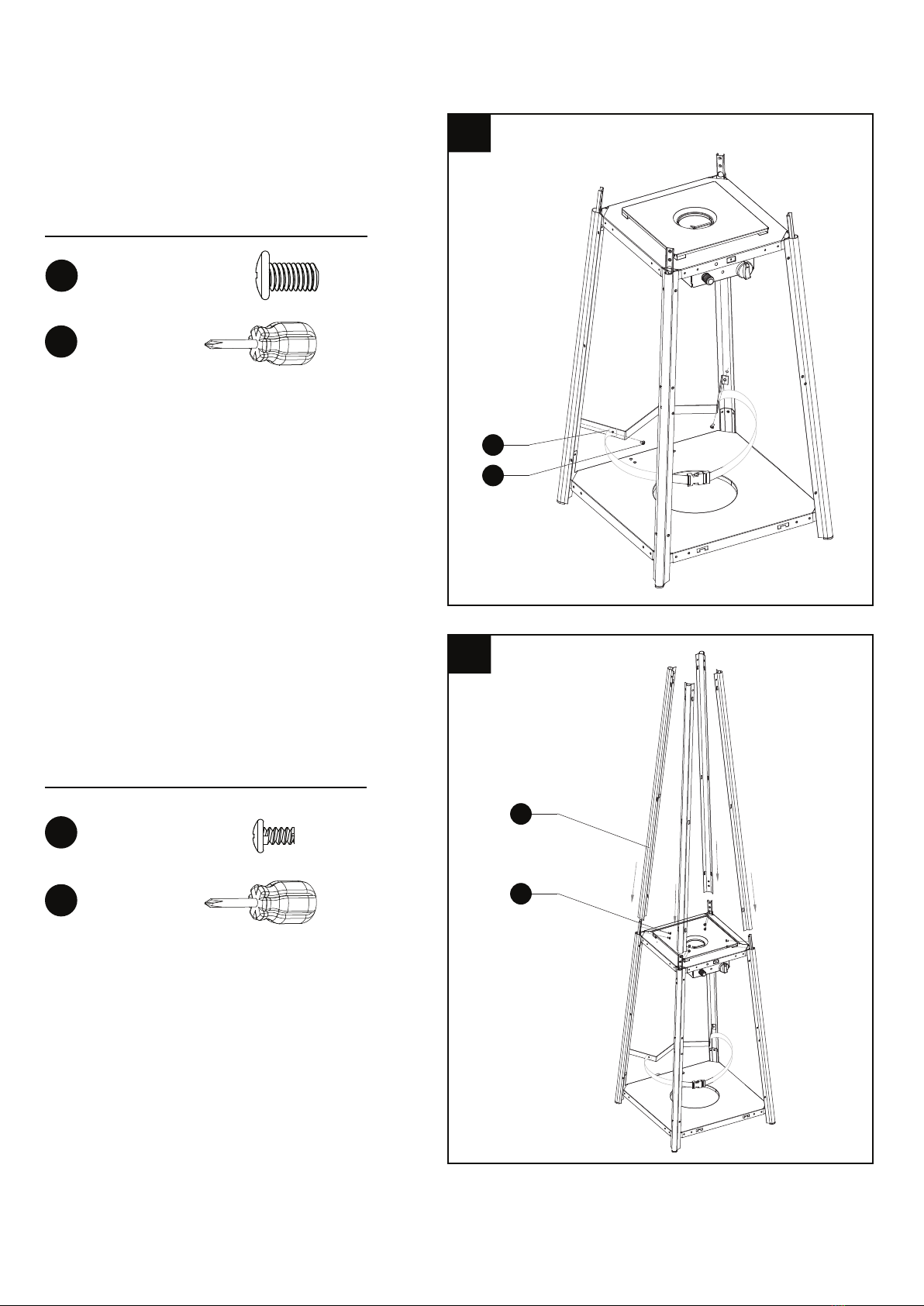
Hardware Used
KK
Hardware Used
3.Assemble block belt.
Fix the block belt to the 2pcs of lower support
behind the front door,using 2pcs screw M5X12.
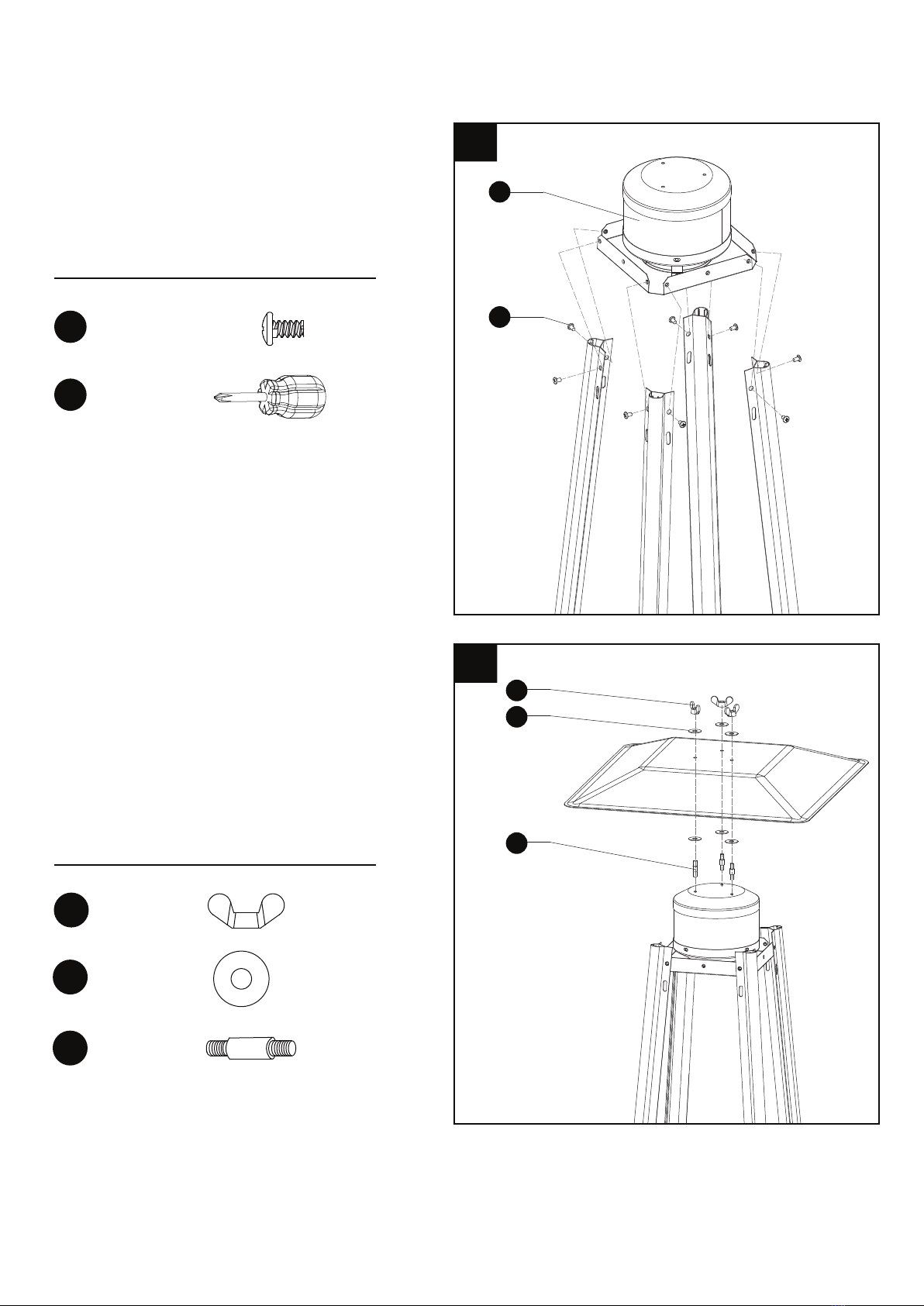
4. Assemble the middle support.
Insert the 4pcs upper support to the lower
support. Secure them with 8pcs screw 3/16”.
x 1
Philips
screwdriver
DD
KK
x 8
x 1
Philips
screwdriver
3/16” Screw
GG x 2
Screw M5 X 12
3
L
GG
4
D
DD
5
Hardware Used
5. Assebmle the flame screen to the upper
support.
Secure the flame screen to the upper support
using 8pcs screw 3/16”.
6. Assemble the reflector onto the flame
screen.
Screw the 3pcs stud on the flame screen,
put 3pcs washer Φ6 onto the top of stud,
then put the reflector onto the stud, secure
them with 3pcs washer Φ6 and 3pcs wing
nut.
x 3
x 3
x 6
Hardware Used
DD
KK
x 8
Philips
screwdriver
3/16” Screw
x 1
5
B
DD
6
AA
BB
CC
AA
BB
Wing nut
Washer Φ6
CC Stud
6

7. Carefully install the glass tube by lifting up
and inserting through the center hole in the
upper plate. Ensure the black silicone ring is
attached to the lower edge of the glass tube
as illustrated. Slide the glass tube through the
hole of the lower plate cover and onto the
middle plate. Check and ensure that the glass
tube is positioned properly and is completely
covering the center hole of the middle plate.
8. Assembly the protective guard.
Hang the hooks of the protective guard onto
the holes in supports.
Secure the protective guards with fixing
brackets with 4pcs 3/16" screws.
WARNING! The black
silicone ring must be in place
prior to operating the heater.
7
To aid in installation
place black silicone
ring on the middle
plate and then
install glass tube.
Ensure the rim of
the glass tube sits
firmly in the black
silicone ring.
BLACK SILICONE
RING
Hardware Used
DD
KK
x 4
Philips
screwdriver
3/16” Screw
x 1
HH Fixing
Bracket x 4
8
E
DD
HH
7

11. LPG Hose Connection.
WARNING! Ensure the hose does not contact
any high temperature surfaces, or it may melt
and leak causing a fire.
After the cylinder is placed inside the heater, secure
the cylinder with block belt tightly.
12. Leak Check.
11
12
Regulator / Cylinder
connection
Hose / Regulator
connection
WARNING!
A leak test must be performed annually and each time a cylinder is connectd or if a part
of the gas system is replaced.
WARNING! Never use an open flame to check for gas leaks. Be certain no sparks or open flames are
in the area while you check for leaks. Sparks or open flames will result in a fire or explosion, damage to
property, serious bodily injury, or death.
Leak testing: This must be done before initial use, annually,and whenever any gas components are replaced
or serviced. Do not smoke while performing this test, and remove all sources of igniion. See Leak Tesing
Diagram for areas to check. Turn all burner controls to the off posiion. Turn gas supply valve on.
Brush a half-and-half soluion of liquid soap and water onto all joints and connecions
of the regulator, hose, manifolds and valves.
Bubbles will indicate a gas leak. Either ighten the loose joint or have the part replaced with one recommended
by the Customer Care department and have the patio heater inspected by a qualified gas technician.
If the leak cannot be stopped, immediately shut off the gas supply, disconnect the cylinder , and have the patio
inspected by a cerified gas installer or dealer. Do not use the patio heater until the leak has been corrected.
8

PRECAUTIONS
APPLIANCE STAND AND LOCATION
BURN-BACK (FIRE IN BURNER TUBE OR CHAMBER)
In the event of a burn-back, where the flame burns back to the jet,
immediately turn off the gas supply at the control valve on the panel.
After ensuring the flame is extinguished, re-light the appliance in the
normal manner. Should the appliance again burn back, close the
control valve and call a service technician. Do not use the appliance
again until the service technician has declared that it is safe to do so.
Installation and services should only be a done qualified person.
Do not use the heater in an explosive atmosphere.
Before use, check the hose.
Disconnect LPG cylinder before moving the heater.
Do not attempt to alter any parts of the heater.
Example: Using the heater without reflector or protection guard.
The appliance shall not be used in basements or below ground level.
It must always be placed on a solid and level surface.
Never replace or substitute the regulator use only that one is suitable both appliance category and normal gas
pressure
The LPG gas cylinder valve should be turned off when the heater is not in use.
Don't not use the heater when it is raining, and do not let any liquid splash to the glass tube when the heater is
Do not paint protection guard, control box or reflector.
Keep the children away from the heater, always be carefully not to knock down the heater, which will break the
glass tube and might cause injury.
Do not move the appliance when in operation.
After a long break of operation, the gas parts in the control box of the heater and the hose should be inspected
for spiders, spider webs or other insects.
Check the heater immediately if any of the following exists:
1. There is smell of gas.
2. The heater is not enough effective.
3. The burner makes popping noise during use (a slight popping noise is normal when the burner is
extinguished
after use).
If you smell gas, turn off the valve immediately. If smell persists, contact the dealer or gas supplier immediately.
The hose with regulator assembly shall be stored in a safe place to avoid it’s accidental damage.
Children and adults should be aware of the high surface temperature hazard, and should keep a safe distance
away to avoid clothes burning or igniting.
Young children should be carefully supervised when they are in the working area of the heater.
Clothing or other flammable material should not be hung from the heater, or placed on or near the heater.
Do not obstruct the flow of combustion products.
Keep the ventilation opening of the cylinder enclosure free and clear of debris.
Do not obstruct the ventilation holes of the cylinder housing.
Shut off the valve of gas cylinder or the regulator before moving the appliance.
The tubing or the flexible hose must be changed within the prescribed intervals.
Use only the type of gas and the type of cylinder specified by the manufacturer.
In case of violent wind particular attention must be taken against tilting of the appliance.
The appliance is for outdoor use only. Do not use
indoors or in an enclosed area.
Always maintain proper clearance from combustible
materials, i.e. top 800mm and sides 650mm minimum
9

INSTALLATION
OPERATION:
PREPARATION:
WARNING:
Never use the heater while it is raining, the glass tube would break when it suddenly met water.
Always turn off the heater while there is a rain.
Never splash any liquid to the glass tube when the heater is working
The glass tube will be extremely hot when it is working, never try to touch it and keep the children away
from the heater.
Always ensure the heater stands firmly, the glass tube may break if the heater was falls down onto ground.
Never use the heater if the glass tube has any cracks
Important safety requirements:
THIS APPLIANCE OUTDOOR USE ONLY
1. This appliance shall not be installed or used indoors, in buildings, garages or any other enclosed area.
2. DO NOT place articles on or against this appliance.
3. DO NOT use or store flammable materials near this appliance.
4. DO NOT operate this appliance unless it is fully assembled with reflector and protection guard in place.
5. Installation and repair should be done by a qualified service person. The appliance must be inspected
before use and at least annually by a qualified service person. More frequent cleaning may be required as
necessary. It is imperative that control compartment, burners and circulating air passages of the heater
and light be kept clean.
You will need to purchase an LPG cylinder
You need a suitable size LPG cylinder that can be installed to the
compartment.
You have to use pressure regulator with an outlet pressure complying
with the appliance category. The flexible tube must be approved also.
Connect the hose to the hose connector in the control box
Warning: Always test the hose for leaks with soapy water at both ends.
To Turn On The Heater
1. Open the cylinder control valve 1½ turns in an anti clockwise direction
O
2. Press and turn the variable control knob on the heater to the PILOT position (90 in an anti- clockwise
direction.
3. Whilst in the Pilot position press in the variable control knob and hold in that position for 30 secs. Whilst
holding the knob in the pressed in position press the ignitor button several times until the pilot flame ignites.
Note:
ŸIf a new cylinder has just been connected to the heater please allow 60 seconds for the air in the gas
hose to purge out of the pilot jet before pressing the ignitor button.
ŸIt is important to hold in the control knob when pressing the ignitor button.
ŸIf the plot flame does not ignite repeat step 3 above.
4. After the pilot flame ignites turn the variable control knob to the maximum position and leave in that position
for 5 mins. or more before turning the control knob to the desired temperature setting
To Turn off the Heater
1. Turn the variable control knob to the PILOT position.
2. Press and turn the variable control knob to the OFF position
3. Turn the cylinder control valve to the closed position in a clockwise direction.
lgnitor
Ignitor button Variable
Control knob
10

CLEANING/MAINTENANCE/STORAGE:
CLEANING AND MAINTENANCE:
To enjoy outstanding performance of your heater for years make sure to perform the following maintenance
activities on a regular basis:
Keep exterior surfaces clean.
-Use warm soapy water for cleaning. Never use flammable, corrosive or abrasive cleaners.
-While washing your unit, be sure to keep the area around the burner and pilot assembly dry at all time.
If the gas control is exposed to water in any way, do NOT try to use it. It must be replaced.
After a long break from operation, the unit should be inspected for spiders, spider webs or other insects.
Air flow must be unobstructed. Keep controls. Burner and circulating air passageways clean.
Signs of possible blockage include:
-Gas odour with extreme yellow tipping of flame.
-Heater does NOT reach the desired temperature.
-Heater glow is excessively uneven.
-Heater makes popping noises.
Spider and insects can nest in burner or orifices.
This dangerous condition can damage heater and render it unsafe for use. Clean burner holes by
using a heavy-duty pipe cleaner.
Compressed air may help clear away smaller particles.
Carbon deposits may create a fire hazard. Clean reflector and glass tube inside with soapy water if any
carbon deposits develop. Always be careful when cleaning the glass tube.
STORAGE:
Between uses:
Turn the control knob to “OFF” position.
Turn LPG cylinder to “OFF” position.
Store heater upright in an area sheltered away from weather conditions (such as rain, sleet, hail, snow).
If desired, cover heater to protect exterior surfaces and to help prevent dust and debris collecting in air passages.
During periods of extended inactivity or when transporting:
Turn the control knob to “OFF” position.
Disconnect LPG Cylinder and move to a secure, well-ventilated location outdoors.
DO NOT store in a location that will exceed 50 degrees C.
Store heater upright in an area sheltered away from weather conditions (such as rain, sleet, hail, snow).
If desired, cover heater to protect exterior surfaces and to help prevent dust and debris collecting in air passages.
WARNING
FOR YOUR SAFETY
Do not touch or move the heater for at least
45 mins. after use.
Allow all burner elements to cool before
touching.
NOTE
In a salt-air environment (such as near an
ocean) corrosion occurs more quickly than
normal.
Frequently check for corroded areas and
repair them promptly.
Wait until heater is cool before covering
11

Distributed by: D.K.Gas Appliances. PO Box 34191 Erasmia 0023
F. Technical specifications
Name TOTAI
Model 16/DK1023A
Heat Output 11.0 KW
Gas Types LPG
Injector Size Ø 1.70mm x 1
Operating Pressure 2.8 kPa
Gas Consumption (at Max ) 800 g/h
NOTE:
TAMPERING: .
FOR OUTDOOR USE ONLY.
Specifications are subject to change without prior notice.
G. Troubleshooting
PROBLEM PROBABLE CAUSE SOLUTION
Gas valve may be OFF Turn the gas valve ON
LPG cylinder empty Refill LPG cylinder
Orifice blocked Clean or replace Orifice
Air in supply system Purge air from lines
Pilot will not light
Loose connection Check all fittings
Debris around pilot Clean dirty area
Loose connection Tighten connection .
Thermocouple bad Replace Thermocouple
Gas leak in line Check connections
Pilot will not stay on
Lack of gas pressure LPG cylinder is near empty
Gas pressure is low LPG cylinder is near empty
Orifice blocked Remove, clean and replace
Control knob not ON Turn knob to ON .
Thermocouple bad Replace Thermocouple
Burner will not light
Pilot light assembly bent
or not in correct location .
Place pilot light in correct Position
and retry
Any repairs to the patio heater must be carried out by a qualified person
Under no circumstances are you allowed to tamper with the jet sizes or modify anything on
the appliance. Not only is it dangerous , it will also nullify your warranty
GAS-PRESSURE REGULATOR—This appliance is designed to operate on a gas pressure
of 2,8 kPa. A suitable regulator that complies with the requirements of SANS 1237 must be
used with this appliance
Hose to be in compliance with SANS 1156-2 or BS 3212. Regulator and hose supplied
12
Table of contents
Other Totai Heater manuals

Popular Heater manuals by other brands

GVA
GVA GVAOC3311TH instruction manual

Steamist
Steamist SMS-45 Installation guide and owner's manual

PAX
PAX TR Series Installation instuctions

Frico
Frico Infrasmart IHS30W/B/S24 Assembly and operating instructions

Timberk
Timberk TOR 21.1005 BCX instruction manual

Herschel
Herschel MANHATTAN 3000 Installation & operating instructions


