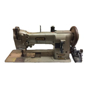
Pfaff 441-O User manual

®442-R
441
-O
442-0
Service
Manual
Pfaff, D
6750
Kaiserslautern,
Postfach
3020/3040,
Telex:
045753
From the library of: Superior Sewing Machine & Supply LLC

Important
note:
ThisServiceManual applies also to the Raff 441-0 and 442-0. Deviations in the illustrations do not
affect
the
adjustment of the machines.
The
Sen/ice
Manual is
based
on a two-needle machine.
When adjusting a single-needle machine,
simply
ignore the adjustment procedure for the left
needle and the left sewing hook. A separate Service
Manual
is available for adjusting the
Pfaff
441-R
(0)-705/03: -755/03.
Tools,
gauges
and
other
items required for adjusting
Raff
machines
442-R, 441-0
and
442-0
1
set
of
screwdrivers
with
blades
from
2
to
10
mm
wide
1
set
ofwrenches withopeningsfrom 7 to 14 mm wide
1
set
of alien keysfrom 2 to 6 mm
1feed dog
gauge,
part No.
91-129995-05
1adjusting
gauge,
part No. 91
-129573-91
1C-clamp,
part
No.
880137/00
1
metal
rule
1wrapper of needles: system 134 (for7 mmfabric clearance)
system
134-35
(for 9 mm fabric clearance)
2strips of white
paper
Sewing thread and testing material
Technical
data
Maximumsewing
speed:
5000 s.p.m.
Balance
wheel:
65
mm
eff.
dia.
Drive:
clutchmotor0,550 kW(% HP)
lever-operated Stop motor0,550 kW(% HP)
electronic-stop-motor 0,550 kW(%HP)
Needle system: 134 (for7 mmfabric clearance)
134-35
(for 9 mm fabric
clearance)
Fabric
clearance:
7
or
9
mm
From the library of: Superior Sewing Machine & Supply LLC

Correct
setting:
Scale
ring
in
reverse-feed
control
With the stitch length
set
at
"0",
the
"0"
mark on scale ring 3 should be opposite
mark
4.
1.0.1
1.1
Take
the
needles
out
of
the
needle
holder.
1.2
Remove
the
knee
levertogetherwith its coupling
sleeve.
1.3
Tum
knurled
disc
1
as
far
as
it will
go
in
the
direction in which
the
reverse-feed
control
starts
to
move
downwards.
1.4
Loosen
screw
2
and
turn
scale
ring
3until
the
"0"
mark
Is
opposite
mark
4.
1.5
Inthis position, tighten
screw
2.
From the library of: Superior Sewing Machine & Supply LLC

Correct
setting:
Zeroing
the
bottom
feed
The
feed
dog
must
not
move
forward
when
you turn
the
balance
wheel
with
the
stitch length
set
at
"0".
2.0.1
2.1
Remove
the
left
upper
plastic plug on
the
back
of
the
arm
standard.
2.2
Unscrew
the
gearcase
cover
on
the
underside
of
the
machine
base
(collecting
the
oil, if
any,
in a container).
2.3
Loosen
screw
1
of
the
counter-balance.
2.4
Make
sure
the
stitch length is
set
at
"0",
then
loosen
both
clamp
screws
2 (Fig. 2.0.1)
just
sufficiently to allow
crank
3 to
be
turned
on
its
shaft
against
resistance.
From the library of: Superior Sewing Machine & Supply LLC

2.5
Tofacilitateadjustment,insertascrewdriverinthe slot offeed rock shaftcrank4 (Fig.2.0.2).
2.0.2
2.0.3
2.6
Turn
the
balance
wheel
and
simultaneously
adjust
rod
5 (Fig. 2.0.3)
connected
to
crank
3 (Fig. 2.0.1) until
the
feed
dog
(or
rather
the
screwdriver
in
the
feed
rock
shaft
crank)
Is
completely
motionless.
2.7
Inthis position, tighten both
clamp
screws
2
securely.
2.8 Leave the screwdriver in the slot of
feed
rock shaftcrank 4 (Fig. 2.0.2) for
the
subsequent
adjustments.
2.9
Check
this
adjustment
(see
"Correct
setting").
From the library of: Superior Sewing Machine & Supply LLC

Correct
setting:
3.0.2
Bottom
feed
driving
motion
With the machine
set
for its longest stitch and the needle bar positioned at bottom
deadcenter, the feed dog should not move when the reverse-feed control is operated.
J
3.0.1
3.1 Loosen both screws 1 (Fig. 3.0.1) Infeed driving eccentric 2 just sufficientlyto allow the
eccentric to be turned on its shaft against resistance.
3.2
Bring
the
needle
bar
to bottom
dead
center.
3.3 Pushthe C-clampontothe needlebar,push itupagainstthe needlebarframeandtighten
its
screw.
3.4
Set
the
machine for its longest stitch.
3.5 Movethe reverse-feed control up and down and simultaneously turn feed driving
eccentric 2 until its notch (see arrow in Fig.3.0.1) is visible and the feed dog (or
rather
the
screwdriverin feed rock
shaft
crank3) is completely motionless.
3.6 Inthis position, securelytighten the accessible screw 1.
3.7
Remove
the
C-clamp
from
the
needle
bar.
3.8
Also tighten
the
second
screw
1.
3.9
Pull
the
screwdriver
out
of
the
slot
in
feed
rock
shaft
crank
3.
3.10 Check this adjustment (see "Correct setting").
From the library of: Superior Sewing Machine & Supply LLC

Correct
setting:
Lower
needle
bar
driving
crank
With the stitch length
set
at "0", the flat surface of lower needle bar driving crank 4
should
be
so
positioned that its
edge
is parallel to
the
edge
of
the
bedplate.
4.0.1
4.0.2
4.1
Take
out
screws
1 of clip bracket 2
and
remove
the
bracket.
4.2
Set
the
machine for its longest stitch.
4.3
Loosen
screws
3.
4.4
Set
the
stitch length at
"0".
4.5 Turn lower
needle
bar
driving
crank
4
so
that
the
edge
of its flat
surface
is parallel
to
the
edge
of
bedplate.
4.6 Inthis position,tighten the accessible screw 3.
4.7 Againset the machineforitslongeststitchand tightenthe second screw3,too.
4.8 Replace bracket2
and
tighten
screws
1.
From the library of: Superior Sewing Machine & Supply LLC

Correct
setting:
5.1
5.2
5.3
5.4
Counter-balance
With
the machine set for its longest stitch, counter-balance 2 should move freely
when
the reverse-feed control is operated.
5.0.1
Set
the
machine for its longest stitch.
Makesure screw 1 ofcounter-balance2 is loose (Fig.5.0.1), move the latteras faras it
will
go, turning itinthe direction indicated by an arrow.
Turnthe counter-balancebackbyabt.1 mmagain, and inthis
position
tighten
screw1.
Check this adjustment
(see
"Correct setting").
From the library of: Superior Sewing Machine & Supply LLC

Correct
setting:
6.1
6.2
6.3
6.4
6.5
6.6
6.7
6.8
6.9
Bottom
feed
lifting
motion
When the needle bar is at bottom
dead
center, the feed dog should be at its
highest
point.
n
W
Set
the
stitch length at
"0".
Loosen
clamp
screw
1.
Turn out
screw
3 incollar 2 by half a turn.
Insert ascrewdriver in
the
slot of bottom
feed
lifting
crank
4
and
bring
the
needle
bar
to
bottom
dead
center.
Push
the C-clamponto
the
needle
bar, push itup
against
the
needle
bar
frame
and
tighten
its
screw.
Turn
coiiar
2
on
the
collar
of
the
lifting
eccentric
until
the
feed
dog
(or
screwdriver)
is
at
bottom
dead
center.
Inthis position, tighten clamp
screw
1.
Remove the C-clampfrom
the
needle
bar
and
tighten
screw
3.
Pull
the
screwdriver
out
of
the
slot
of bottom
feed
lifting
crank
4
and
check
this
adjustment
(see
"Correct
setting").
From the library of: Superior Sewing Machine & Supply LLC

Correct
setting:
7.1
7.2
7.3
7.4
7.5
7.6
7.7
Note:
Clearance
between
presser
foot
and
needle
plate
Withpresserbar lifter1 raised, there shouid be a ciearance of7.0 mm (needie system
134) or 9.0 mm (needle system 134-35) between presserfootand needle plate.
7mm(9mm)
f
Take
out
the
two
screws
of
the
face
cover
and
remove
the
latter.
Unscrew
the
cover
on
the
back
of
the
machine
arm.
Raise
presser
bar lifter1 and screw on the
presser
foot.
Loosen both
screws
2 inthe
presser
bar collar.
Push the 7-mm (or9-mm)thickpart ofthe gauge under the presserfootso that itsrecess
faces downwards (Fig.7.0.1).
Push the presserfoot downonto the gaugeand adjustItlaterally
so
that its
sides
are
parallel to
the
edges
of
the
needle
plate
slot.
Inthis position, tighten both screws 2.
Adjust
the presser footpressure by
turning
regulating
screw4
(Fig.
9.0.1)inor outwhen
you
make
asewing test.
From the library of: Superior Sewing Machine & Supply LLC

Correct
setting:
Feed
dog
height
Withthe stitch length
set
at
"0"
and
the
needle
bar
positioned at bottom
dead
center,
the feed dog should be centered in its slots and contact the gauge throughout its
entire length (Fig. 8.0.2).
2
8.1
Set
the
stitch length at
"0".
8.2
Bring
the
needle
bar
to bottom
dead
center.
8.3 Loosenclamp
screws
1 offeed liftingcrank2
and
clamp
screws
3 offeed rockshaftcrank4.
8.4
Place
the
machine feed
gauge
so
under
the
presser
foot that its
recess
faces
downwards
and
its front
edge
is flush with
the
front
edge
of
the
needle
plate.
8.5
Lower
the
presser
bar
lifterto
rest
the
presser
foot on
the
gauge.
8.6
Center
the
feed
dog
in
its
slots.
8.7
Push
the
feed
bar
upwardsuntil
the
feed dog
contacts
the
gauge,
and
hold itinthis position.
From the library of: Superior Sewing Machine & Supply LLC

8.8 Turn
eccentric
bushing
5
located
under
feed
rock
shaft
crank
4 until
the
feed
dog
is
in
contact
with
the
gauge
throughout
its
entire
length
(Fig. 8.0.2);
the
feed
dog
now
protrudes
1.1
mm
from
the
needle
plate
surface.
8.9 inthis position, tighten clamp
screws
1
and
3, making
sure
that
the
feed dog is still
centered
in
its
slots.
8.10
Check
this adjustment
(see
"Correctsetting").
8.11
Raise
the
presser
bar
lifter and remove the
gauge
from under
the
presser
foot.
10
From the library of: Superior Sewing Machine & Supply LLC

Correct
setting:
Centering the
needles
in
the
needle holes
With
the stitch length set at "0", the needles should be centered exactly Inthe re
spective needle holes. (ItIsrecommended to Inserttwonew needles)
9.0.2
9.1 Unscrew the coveron the back of the machine arm
near
the balancewheel.
9.2
Unscrew
the presser footand the threadtensionbase plate.
9.3 Set thestitchlengthat"0", and
bring
the needlebartotopdead center.
9.4 inserttwoneedles
Into
the needleholderso thattheir
long
groovesfaceeach other(note
the
needle
system).
9.5 Loosenscrew11ncollar2 onthe needle bar
driving
shaft
which
isaccessiblethroughthe
aperture (see arrowin Fig.9.0.1).
9.6
Aiso
loosen
clamp
screw3 inthe needlebar
driving
crank
(Fig.
9.0.3).
11
From the library of: Superior Sewing Machine & Supply LLC

9.7
Turn
the
balance
wheel
to position
the
needles
above
the
needle
holes.
9.8
Turn
the
balance
wheel
while
moving
the
needle
bar
frame
sideways
until
both
needles
are
centered
in
their
needle
holes
both
lengthwise
and
crosswise
(Fig. 9.0.2).
9.9 Inthis position, push coilar 2 to the right
as
far
as
it
wiii
go and tighten screw 1.
9.10 Also tighten clamp screw 3, making
sure
the needle bar drivingshaft
has
no end play.
9.11
Check
this
adjustment
(see
"Correct
setting").
9.0.3
12
From the library of: Superior Sewing Machine & Supply LLC

10
Preliminary
adjustment
of
needle
bar
height
Correct When the needle bar Isat top
dead
center, there should be a clearance of 17 mm be
setting: tweenneedlepointand needle plateon
Model
S machines,and a clearanceof22mm
on
Model
L
machines.
Model
S =
33
mm
needle
bar
stroke
Model
L =
38
mm
needle
bar
stroke
17mm(22mm)
10.0.1
10.0.2
10.1 Bringthe needle bar to top
dead
center.
10.2 Loosen hexagon screw 1 inthe needle bar connecting stud.
10.3
Adjust
the needlebarvertically untilthere is a clearanceof17mmbetweenneedle
point and needle plate on
Model
S machines, or a ciearance of22mmon
Model
L
machines.
Make
sure
the
needie
bar
is
not
turned
in
the
process.
10.4 Inthis position, tighten hexagon screw 1.
13
From the library of: Superior Sewing Machine & Supply LLC

11
Correct
setting:
Hook timing,
hook-to-needle
clearance
and
needle
bar
height
Withthe stitch length
set
at
"0"
and the needlebar positioned 1.8 mm
past
bottom
dead
center(needle rise position)each hook pointshould be exactly oppositethe centerline
of the respective needle, the lateral clearance between hook point and needle being
0.1 mm. Also, Inthis position, the hook points should be positioned 0.8 mm above the
top
edge
of the respective
needle
eye.
\
11.0.1
11.0.2
11.0.3
11.1
Set
the stitch length at
"0".
11.2 Unscrewthe needle plate and the feed dog.
11.3
Loosen
alien
screw1,
which
Isaccessible
through
the holeinthe
bevel
gearcase
cover,
and alien screw 2 between both bevel gearcases.
11.4
Loosen
both
screws
3,
which
areaccessible
through
the
holes
inthe
bevel
gearcases.
14
From the library of: Superior Sewing Machine & Supply LLC

11.5
Loosen
screws
4 of
the
bobbin
case
opener
eccentrics.
11.6 Also loosen hexagon screws 5 ofthe hook bearing brackets.
11.7 Bringthe needle bar to bottom
dead
center.
11.8
Push
the 1.8-mm-thick blade of
the
gauge
onto
the
needle
bar immediately below its
lower bearing, push the C-clamp up against the blade and tighten its screw.
11.9 Pull out the gauge and turn the balance wheel in its normal direction
until
the C-clamp
contacts
the
needle
bar
bearing.
11.10 Turn
both
hooks
on
their
shafts
so
that
their
points
are
opposite
the
center
iine of
the
respective needle. Inthis position(needle rise position), the hook points should be
positioned0.8 mmabove the top edge ofthe respective needle eye. Ifnecessary, adjust
the
needle
bar height.
11.11
Adjust the hook bearing brackets laterally until there is a clearance of 0.1 mm be
tween
the
hook
points
and
the
needles.
11.12 Inthis position, securely tighten hexagon screws 5.
11.13 Adjustthe leftpart ofthe maindriveshaft so that the clutchhas a playof0.5 mm.
11.14 Inthis
position,
tightenalienscrews 1 and 2, makingsure that the bevelgears are neither
set
too
close
nor
have
too much play.
11.15 Tightenone each ofscrews 4 ofthe bobbin
case
opener eccentric.
11.16 Push the bushings up against the bevel gears and tightenbothscrews 3 on each.
11.17 Remove the C-clamp fromthe needle bar.
11.18 Check this adjustment
(see
"Correct setting").
11.19 Do not tighten the second screws 4
as
yet.
Note: In
case
the hooks have to be exchanged, make surethe marks on hook bearing and hook
are
on the
same
side
(see
Fig. 11.0.4)
15
From the library of: Superior Sewing Machine & Supply LLC

12
12.1
Correct
setting:
12.0.1
12.1.1
12.1.2
12.1.3
12.1.4
12.1.5
12.1.6
Bobbin
case
openers
Right bobbin
case
opener
eccentric
When
thetake-upleverisat
bottom
deadcenter,shaft3ofthe
right
bobbin
caseopener
should
be
exactly
atitsrear
point
ofreversal, asseeninthe
direction
offeed(see
arrow).
a
Screw on the feed dog.
Also
screwontheneedle
plate,
making
surethatthelugsof
both
bobbin
case bases enter
the
appropriate
slotsonthe
underside
ofthe needle
plate.
Loosen
screw
1
in
the
right
bobbin
case
opener
eccentric,
which
was
tightened
previously.
Turnthe balancewheelto
bring
the take-upleverto
bottom
dead center.
Turn
the
right
bobbin
case openereccentric 2onitsshaft
until
shaft3is
exactly
at
its rearpointof reversal
(see
arrow).
Inthis
position,
tighten
screws1 securely.
16
From the library of: Superior Sewing Machine & Supply LLC

12.2
Left
bobbin
case
opener
eccentric
Correct
setting: When
the
take-up lever Isat bottom
dead
center,shaft6 of
the
left bobbin
case
opener
shouldbe exactlyat itsfront pointofreversal,
as
seen
inthe direction offeed
(see
arrow).
12.2.1
Loosen
screw
4 in
the
left bobbin
case
opener
eccentric, which
was
tightened previously.
12.2.2
Turn
the
balance
wheel
to bring
the
take-up
leverto bottom
dead
center.
12.2.3
Turn
the
left
bobbin
case
opener
eccentric
5
on
its
shaft
until
shaft
6
is
exactly
at
its
front
point
of
reversal
(see
arrow).
Inthis position, tighten
screw
4securely.
17
From the library of: Superior Sewing Machine & Supply LLC

12.3
Right
bobbin
case
opener
Correct Whenshaft 1ofthe rightbobbin
case
opener isat itsrear pointofreversal (see arrow),
setting:
as
seen
inthe direction of feed,
there
should be a
clearance
of 0.3 to 0.5 mm
between
the lugofthe rightbobbin
case
base
and the rear
edge
ofthe needie plate slot.
12.3.1
12.3.2
12.3.3
12.3.4
12.3.5
12.3.6
12.0.2
12.0.3.
Bring
the
needle
bar
to bottom
dead
center.
Turn
the
balance
wheel
inits
normal
direction
until
shaft1ofthe
right
bobbin
case
opener
is at its rear pointof reversal (see arrow).
Loosenclampscrew2 ofthe connecting crankonthe
right
shaft1.
Reposition
the
connecting
crank
on its
shaft
so
that
there
is a
clearance
of 0.3 to
0.5mmbetweenthe lugofthe rightbobbincase base andthe rearedgeofthe needle
plate
slot.
In
this
position,
tighten
clamp
screw
2,
making
surethatthe
connecting
crank
isnot
tilted.
Checkthis adjustment(see "Correct setting").
18
From the library of: Superior Sewing Machine & Supply LLC
This manual suits for next models
2
Table of contents
Other Pfaff Sewing Machine manuals

Pfaff
Pfaff Embroidery Machines User manual

Pfaff
Pfaff 8310-041 User manual

Pfaff
Pfaff Coverstyle User manual

Pfaff
Pfaff 130-6 User manual

Pfaff
Pfaff Creative Vision Manual

Pfaff
Pfaff 6500 Series User manual

Pfaff
Pfaff Series 580 Owner's manual

Pfaff
Pfaff varimatic 6089 User manual

Pfaff
Pfaff Creative 7530 User manual

Pfaff
Pfaff 1029 User manual

Pfaff
Pfaff Sewing Machine Guide

Pfaff
Pfaff 918 User manual

Pfaff
Pfaff 481 User manual

Pfaff
Pfaff 3119 User manual

Pfaff
Pfaff 335 User manual

Pfaff
Pfaff COVERLOCK 3.0 - User manual

Pfaff
Pfaff 436 User manual

Pfaff
Pfaff creative 4874 User manual

Pfaff
Pfaff tiptronic 2040 User manual

Pfaff
Pfaff 5480 series User manual