4I66 2
HARDWARE CONFIGURATION
GENERAL
Hardwaresetupjumperpositions assumethatthe4I66cardis orientedinanupright
position, that is, with the PC/104 connectors towards the person doing the configuration,
and the on card writing right-side-up.
PC104-PLUS SLOT NUMBER
The4I66cardmustbeassignedaslot numberbeforeuse.IndesktopPCIsystems,
the slot number is determined by the physical slot that the PCI card is inserted into. In
PC104-PLUS systems, all signals on the bus are the same for each card, so a method is
needed to differentiate each card. This is done with the slot number jumpers on the 4I66
card. 2 jumpers. W2 and W3 determine the 4I66 slot assignment. The following table
shown the jumper settings:
W2 W3 SLOT IRQ REQ/GNT NOTES
DOWN DOWN 0 A 0 DEFAULT
DOWN UP 1 B 1
UP DOWN 2 C 2
UP UP 3 D 2 SHARES SL2 REQ/GNT
MDIX ENABLE/DISABLE
The 4Ethernet ports of the 4I66support Auto MDI-X. When Auto MDI-X is enabled,
each Ethernet port automatically detects whether a crossover connection is required and
switches the ports transmit and receive pairs as needed. Sometimes this auto-switching
can interfere with proper operation of other connected hubs or switches so it can be
disabled. W4 controls the MDIX feature. When W4 is in the right hand position (default),
Auto MDI-X is enabled. When W4 is in the left hand position, Auto MDI-X is disabled.
BOOT EPROM
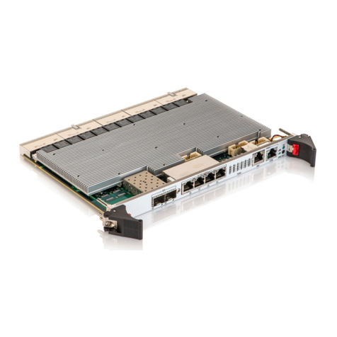
The 4I66 can accommodate a boot EPROM or Flash EEPROM. Socket U8 is
provided for the EPROM or flash EEPROM. The 4I66 will only support 3.3V ,32 pin
EPROM and Flash EEPROMs.
ETHERNET ADDRESS
The hexadecimal MAC address is printedona label on thefront edge of thePC/104
connector of the 4I66 card.
