MESSKO Pt-MU User manual

Pt-MUPt-MU
Pt-MUPt-MU
Pt-MU
Instrucciones de servicio / Operating Instructions 2042
www.messko.de
Convertidor de medición / Transducer
Messko

2BA 2042/00/08
Indice de sontenidosIndice de sontenidos
Indice de sontenidosIndice de sontenidos
Indice de sontenidos
11
11
1SeguridadSeguridad
SeguridadSeguridad
Seguridad ................................................................................................................................................
................................................................................................................................................
........................................................................ 33
33
3
1.1 Instrucciones de seguridad .................................................. 3
1.2 Empleo conforme a lo prescrito ......................................... 3
1.3 Instrucciones para el servicio del equipo .......................3
22
22
2Descripción del productoDescripción del producto
Descripción del productoDescripción del producto
Descripción del producto ..........................................................................................
..........................................................................................
............................................. 44
44
4
33
33
3MontajeMontaje
MontajeMontaje
Montaje ........................................................................................................................................................
........................................................................................................................................................
............................................................................ 44
44
4
44
44
4Conexión eléctricaConexión eléctrica
Conexión eléctricaConexión eléctrica
Conexión eléctrica ....................................................................................................................
....................................................................................................................
.......................................................... 44
44
4
4.1 Circuito de 2 conductores .................................................... 5
4.2 Circuito de 3 conductores .................................................... 5
4.3 Circuito de 4 conductores .................................................... 5
4.4 Señal de corriente continua ................................................. 5
4.5 Señal de tensión continua.................................................... 6
55
55
5Características técnicasCaracterísticas técnicas
Características técnicasCaracterísticas técnicas
Características técnicas ..................................................................................................
..................................................................................................
................................................. 66
66
6
66
66
6AnexoAnexo
AnexoAnexo
Anexo ................................................................................................................................................................
................................................................................................................................................................
................................................................................ 77
77
7
Indice de dontenidos / Contents
Guardar para uso posterior!
ContentsContents
ContentsContents
Contents
11
11
1SafetySafety
SafetySafety
Safety ..............................................................................................................................................................
..............................................................................................................................................................
............................................................................... 33
33
3
1.1 Safety instructions .................................................................. 3
1.2 Specified application.............................................................. 3
1.3 Important notes on equipment operation....................... 3
22
22
2PrPr
PrPr
Product specificationoduct specification
oduct specificationoduct specification
oduct specification ..........................................................................................................
..........................................................................................................
..................................................... 44
44
4
33
33
3InstallationInstallation
InstallationInstallation
Installation ............................................................................................................................................
............................................................................................................................................
...................................................................... 44
44
4
44
44
4Electrical connectionElectrical connection
Electrical connectionElectrical connection
Electrical connection ..........................................................................................................
..........................................................................................................
..................................................... 44
44
4
4.1 2-wire configuration .............................................................. 5
4.2 3-wire configuration .............................................................. 5
4.3 4-wire configuration .............................................................. 5
4.4 Direct current signal ............................................................... 5
4.2 Direct voltage signal .............................................................. 6
55
55
5TT
TT
Technical dataechnical data
echnical dataechnical data
echnical data ..................................................................................................................................
..................................................................................................................................
................................................................. 66
66
6
66
66
6AppendixAppendix
AppendixAppendix
Appendix ....................................................................................................................................................
....................................................................................................................................................
.......................................................................... 77
77
7
Please keep this manual on hand for future reference!
ADVERTENCIAADVERTENCIA
ADVERTENCIAADVERTENCIA
ADVERTENCIA
Las indicaciones contenidas en el presente manual de servicio
pueden diferir del aparato suministrado.
Reservado el derecho a realizar modificaciones.
HINWEISHINWEIS
HINWEISHINWEIS
HINWEIS
Data contained herein may differ in details from the
equipment delivered.
We reserve the right to make alterations without notice.
3
BA 2042/00/08
Messko
1 Seguridad / Safety
11
11
1SeguridadSeguridad
SeguridadSeguridad
Seguridad
1.11.1
1.11.1
1.1 Instrucciones de seguridadInstrucciones de seguridad
Instrucciones de seguridadInstrucciones de seguridad
Instrucciones de seguridad
Toda persona involucrada en los trabajos de montaje, puesta en
servicio, operación, mantenimiento y conservación del equipo
debe
- estar lo suficientemente cualificada técnicamente y
- tener en cuenta estas instrucciones de uso.
En caso de uso inadecuado o mal uso existe peligro para
- la salud y la vida de personas,
- el propio equipo y otros bienes del usuario y
- el funcionamiento eficaz del equipo
En el presente manual de servicio se utilizan tres tipos diferentes
de señales de seguridad para poner de relieve información
importante.
11
11
1SafetySafety
SafetySafety
Safety
1.11.1
1.11.1
1.1 Safety instructionsSafety instructions
Safety instructionsSafety instructions
Safety instructions
All personnel involved in installation, commissioning, operation
or maintenance of this equipment must:
- be suitably qualified and
- strictly observe these operating instructions.
Improper operation or misuse can lead to
- serious or fatal injury,
- damage to the equipment and other property of the user
- a reduction in the efficiency of the equipment.
Safety instructions in this manual are presented in three diffe-
rent forms to emphasize important information.
1.21.2
1.21.2
1.2 Empleo conforme a lo prescritoEmpleo conforme a lo prescrito
Empleo conforme a lo prescritoEmpleo conforme a lo prescrito
Empleo conforme a lo prescrito
El convertidor de medición Pt-MU sirve para separar y convertir
una señal de entrada Pt100 en una señal de tensión continua
aplicada y corriente continua independiente.
Antes de la puesta en marcha del aparato, observar y respetar los
valores límites indicados en la placa de identificación y en los
manuales de instrucciones.
1.31.3
1.31.3
1.3 Instrucciones para el servicio del equipoInstrucciones para el servicio del equipo
Instrucciones para el servicio del equipoInstrucciones para el servicio del equipo
Instrucciones para el servicio del equipo
El usuario debe respetar las disposiciones nacionales en materia
de prevención de accidentes.
Se llama especialmente la atención sobre el hecho de que los
trabajos con piezas activas, es decir, con piezas cuyo contacto
entrañeunpeligro,sóloestánpermitidoscuandolaspiezasestén
fuera de tensión o protegidas contra un contacto directo.
Observar las disposiciones nacionales referentes a la instalación
eléctrica.Esprecisoconectarelconductorprotectorparagarantizar
un servicio sin averías.
1.21.2
1.21.2
1.2 Specified applicationSpecified application
Specified applicationSpecified application
Specified application
The measuring transducer Pt-MU serve to isolate and convent a
Pt100-signalinto a load-independentdirect-current and direct-
voltage signal.
It is important to read and observe the limit values for operation
indicated on the nameplate and in the operating instructions
prior to commissioning the device.
1.31.3
1.31.3
1.3 Important notes on equipment operationImportant notes on equipment operation
Important notes on equipment operationImportant notes on equipment operation
Important notes on equipment operation
The user is obliged to comply with the national health and safety
regulations.
It is especially emphasized that works performed to live, i.e.
dangerous-contactcomponents, arepermissible onlywhilethese
components are either de-energized or protected against direct
contact.
Electrical installation is subject to the relevant national safety
regulations. It is imperative to connect the protective conductor
in order to ensure trouble-free operation.
PELIGROPELIGRO
PELIGROPELIGRO
PELIGRO
Se utiliza para llamar la atención sobre peligros especiales
para la integridad física y la vida. Si no se observan tales
indicaciones podrán producirse lesiones graves o mortales.
WARNINGWARNING
WARNINGWARNING
WARNING
This information indicates particular danger to life and health.
Disregarding such a warning can lead to serious or fatal injury.
ATENCIÓNATENCIÓN
ATENCIÓNATENCIÓN
ATENCIÓN
Se utiliza para llamar la atención sobre peligros para el equipo
u otros bienes del usuario. Asimismo, cuando se utiliza esta
señal, no pueden excluirse peligros para la integridad física y
la vida.
.
CAUTIONCAUTION
CAUTIONCAUTION
CAUTION
This information indicates particular danger to the equipment
or other property of the user. Serious or fatal injury cannot
be excluded.
ADVERTENCIAADVERTENCIA
ADVERTENCIAADVERTENCIA
ADVERTENCIA
Se utiliza para llamar la atención sobre información relevante
sobre cualquier tema determinado.
NONO
NONO
NOTETE
TETE
TE
These notes give important information on a certain issue.
4BA 2042/00/08
2 Descripción del producto / Product specification
44
44
4Conexión eléctricaConexión eléctrica
Conexión eléctricaConexión eléctrica
Conexión eléctrica 44
44
4Electrical connectionElectrical connection
Electrical connectionElectrical connection
Electrical connection
ATENCIÓNATENCIÓN
ATENCIÓNATENCIÓN
ATENCIÓN
Según el presente manual de instrucciones, sólo personal
formado y cualificado está autorizado a realizar el montaje y
la conexión eléctrica.
El operador debe asegurarse de que el aparato se utilice
únicamente para los fines prescritos.
Por razones de seguridad durante el montaje y la conexión
eléctrica, está prohibido realizar trabajos de forma inadecuada
y por iniciativa propia en el aparato, sin consultar previamente
a Messko.
CAUTIONCAUTION
CAUTIONCAUTION
CAUTION
Installation and electrical connection of the device may only
be carried out by qualified, skilled personnel and only in
accordance with these operating instructions.
It is the responsibility of the user to make sure that the device
is used for the specified application only.
For safety reasons, any unauthorized and improperly executed
works, i.e. installation or electrical connection of the
equipment, are forbidden without first consulting Messko!
ATENCIÓNATENCIÓN
ATENCIÓNATENCIÓN
ATENCIÓN
La conexión eléctrica solo puede ser realizada por personal
cualificado y formado, instruido en lo que respecta a las
disposiciones de seguridad vigentes en el país
correspondiente.
Utilizar herramientas eléctricas adecuadas.
CAUTIONCAUTION
CAUTIONCAUTION
CAUTION
Electrical connection may only be carried out by qualified,
skilled personnel trained in the applicable health & safety
regulations of the relevant country.
It is imperative to use suitable electric tools.
El montaje se realiza mediante una sujeción de resorte a un raíl
normalizado de 35 mm conforme a DIN EN 50022 en la parte
posterior del equipo. Estos equipos están indicados para ser
montadosuno juntoal otro.Cuandola temperaturaambiente sea
superiora 45°C,se recomiendamantenerunadistanciade 10mm.
El lugar de montaje no debe vibrar ni superar una temperatura
ambiente de 70°C.
The measuring transducer is mounted to a standardized 35mm
rail acc. to DIN EN 50022 using the snap-on fixing located on the
rear face. The measuring transducers are perfectly suited for
installation right next to each other. However, in the presence of
ambient temperatures >45°C a distance of 10mm between the
devices is recommended. The installation location should be
non-vibrating and the ambient temperature must not exceed
70°C.
33
33
3MontajeMontaje
MontajeMontaje
Montaje
ATENCIÓNATENCIÓN
ATENCIÓNATENCIÓN
ATENCIÓN
Deben cumplirse de forma estricta las condiciones de servicio
y de montaje que figuran en estas instrucciones de servicio.
33
33
3InstallationInstallation
InstallationInstallation
Installation
CAUTIONCAUTION
CAUTIONCAUTION
CAUTION
The operating and installation conditions demanded by this
operating manual must be strictly complied with.
22
22
2Descripción del productoDescripción del producto
Descripción del productoDescripción del producto
Descripción del producto
Elconvertidor demediciónPt-MU transformauna señalPt100en
una corriente independiente y/o tensión aplicada. Está indicado
paraserconectadoauntermómetroderesistenciaPt100(conforme
a IEC 751), p. ej., ZT-F2 o manguito combinado. La señal Pt100 se
transforma en una señal de corriente o tensión proporcional a la
temperatura(p. ej.,4...20 mAy2...10 V).La señaldesalida sepuede
utilizar para ser procesada en una indicación digital acoplada
y/o indicador de bobina móvil o sistema informático.
22
22
2PrPr
PrPr
Product specificationoduct specification
oduct specificationoduct specification
oduct specification
The Pt-MU transducer converts a Pt100 signal into a proporti-
onal current or voltage. It can be connected to the Pt100 resistor
thermometer (as per IEC 751), for example ZT-F2 or combi well.
The Pt100 signal is converted into a current or voltage signal
(e.g., 4 to 20mA and 2 to 10V) proportionate to the temperature.
For further processing, the output signal can be sent to a digital
display or moving coil indicator installed after this or to a
computer system.
PELIGROPELIGRO
PELIGROPELIGRO
PELIGRO
Es absolutamente necesario observar las normas nacionales
en materia de prevención de incendios.
WARNINGWARNING
WARNINGWARNING
WARNING
All relevant fire protection regulations must be strictly
observed.

5
BA 2042/00/08
Messko
4 Conexión eléctrica / Electrical connection
4.14.1
4.14.1
4.1 Circuito de 2 conductoresCircuito de 2 conductores
Circuito de 2 conductoresCircuito de 2 conductores
Circuito de 2 conductores
La resistencia de línea entre Pt100 y Pt-MU debe ser inferior a 10
W.La resistenciade lalínease ajustacon elpotenciómetro„ZERO“
bajo la mirilla del equipo. El Pt100 se conecta a los bornes 1 y 3,
los bornes 3 y 4 deben puentearse.
4.44.4
4.44.4
4.4 Señal de corriente continuaSeñal de corriente continua
Señal de corriente continuaSeñal de corriente continua
Señal de corriente continua
En caso de conectar varios equipos de evaluación (p. ej., aparatos
de distribución, reguladores, equipos de medición, registrador,
etc.) a entradas de corriente, deberán conectarse en línea con la
salida del convertidor de medición (observar la polaridad). No se
debe superar la carga máxima de 750 W(incl.laalimentación).La
conexión se realiza a los bornes 13 y 14.
4.24.2
4.24.2
4.2 Circuito de 3 conductoresCircuito de 3 conductores
Circuito de 3 conductoresCircuito de 3 conductores
Circuito de 3 conductores
Aquí no se precisa ajustar las resistencias (<100W).
El Pt100 se conecta a los bornes 2 y 3, la línea de compensación
se conecta al borne 4.
4.34.3
4.34.3
4.3 Circuito de 4 conductoresCircuito de 4 conductores
Circuito de 4 conductoresCircuito de 4 conductores
Circuito de 4 conductores
Al conectar el Pt100 con la técnica de 4 conductores, ajustar los
interruptores DIL al equipo según se indica en la figura 5. No se
precisa ajustar las resistencias (<100W).
El Pt100 se conecta a los bornes 2 y 3, las líneas de compensación
se conectan a los bornes 1 y 4.
4.14.1
4.14.1
4.1 2-wir2-wir
2-wir2-wir
2-wire cire cir
e cire cir
e circuitcuit
cuitcuit
cuit
The line resistance between Pt100 and the Pt-MU must be less
than 10W. Calibration of the line resistance is done with the
„ZERO“ potentiometer under the viewing window of the device.
The Pt100 is connected to terminals 1 and 3. Terminals 3 and 4
must be jumpered.
4.24.2
4.24.2
4.2 3-wir3-wir
3-wir3-wir
3-wire cire cir
e cire cir
e circuitcuit
cuitcuit
cuit
Calibration of the line resistances (< 100W) is not necessary
here. The Pt100 is connected to terminals 2 and 3. The
compensation line is connected to terminal 4
4.34.3
4.34.3
4.3 4-wir4-wir
4-wir4-wir
4-wire cire cir
e cire cir
e circuitcuit
cuitcuit
cuit
When the Pt100 is connected with 4-wire technology, the DIL
switches on the device must be set as shown in figure 5.
Calibration of the line resistances (< 100W) is not necessary. The
Pt100 is connected to terminals 2 and 3. The compensation lines
are connected to terminals 1 and 4.
4.44.4
4.44.4
4.4 DirDir
DirDir
Direct currect curr
ect currect curr
ect current signalent signal
ent signalent signal
ent signal
When several evaluation devices (e.g., switching and regulating
devices, measuring devices, writers and so on) are connected to
the current output, these must be circuited in series to the
transducer (make sure that polarity is correct). The maximum
load of 750W(including the feeder line) may not be exceeded.
Connection is made to terminals 13 and 14.
Técnica de 2 conductores / 2-wire configuration
Figura 1 / Fig. 1
Técnica de 3 conductores / 3-wire configuration
Figura 2 / Fig. 2
Técnica de 4 conductores / 4-wire configuration
Figura 3 / Fig. 3
6BA 2042/00/08
5 Características técnicas / Technical Data
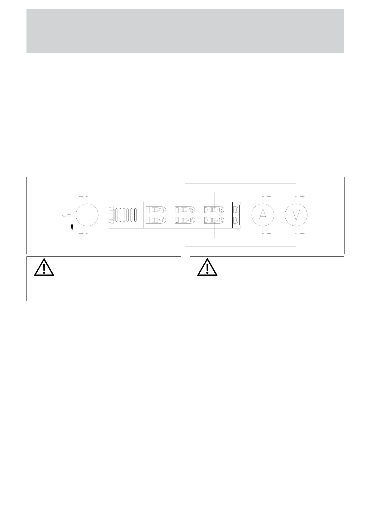
4.54.5
4.54.5
4.5 Salida de tensión aplicadaSalida de tensión aplicada
Salida de tensión aplicadaSalida de tensión aplicada
Salida de tensión aplicada
Encaso de conectar varios equipos de evaluación (p. ej., aparatos
de distribución, reguladores, equipos de medición, registrador,
etc.)aentradadecorriente,seráprecisohacerlodeformaparalela
alasalidadelconvertidordemedición(observarlapolaridad).La
conexión se realiza a los bornes 15 y 16. La salida solo puede
soportar un máx. de 20 mA.
En caso de utilizar las dos salidas al mismo tiempo, la salida de
tensión podrá ser de máx. 1 mA. No está permitido conectar las
dos salidas.
Los equipos están dotados de transformadores resistentes a
cortocircuitos,se puede renunciaraun dispositivodeprotección
contra sobreintensidad para el convertidor.
4.54.5
4.54.5
4.5 DirDir
DirDir
Direct voltage signalect voltage signal
ect voltage signalect voltage signal
ect voltage signal
When several evaluation devices (e.g., switching and regulating
devices, measuring devices, writers and so on) are connected to
the voltage output, these must be circuited parallel to the
transducer (make sure that polarity is correct). Connection is
made to terminals 15 and 16. The maximum load of the output
is 20mA.
When both outputs are used simultaneously, the maximum load
of the voltage output is 1mA. Connection between the two
outputs is not permitted.
The devices are equipped with short-circuit-proof transformers.
Thismakes the use ofovercurrentprotection unnecessary forthe
transducer itself.
55
55
5Características técnicasCaracterísticas técnicas
Características técnicasCaracterísticas técnicas
Características técnicas
EntradaEntrada
EntradaEntrada
Entrada
Tamañoentrada: Pt100 conforme a IEC 751
Margen de medición: 0...160°C ó -20...140°C
Técnica de 2 conductores: Resistencia de línea <10 W, ajuste
mediante potenciómetro
Técnica de 3 conductores: Resistencia de línea <100W, no se
precisa ajuste
Técnica de 4 conductores: Resistencia de línea <100W, no se
precisa ajuste
Tensiónauxiliar: 230VAC±20% 45-65 Hz, 2,5 VA
SalidaSalida
SalidaSalida
Salida
Tamañosalida: Corriente continua independiente y
tensión continua aplicada según
placa de identificación (p. ej.,
4...20mA y 2...10 V)
Salida de corriente: Carga máx. 750 W
Salida de tensión: Carga máx. 20mA, al utilizar las dos
salidas: máx. 1mA
RelacióndetransmisiónRelacióndetransmisión
RelacióndetransmisiónRelacióndetransmisión
Relacióndetransmisión
Precisión: ±1% hasta 70°C
Margende temperatura: -15...+70°C
55
55
5TT
TT
Technical Dataechnical Data
echnical Dataechnical Data
echnical Data
InputInput
InputInput
Input
Input size: Pt100 as per IEC 751
Meas. range: 0 to 160°C or -20 to 14°C
2-wire technique: Line resistance < 10W, calibration with
potentiometer
3-wire technique: Line resistance < 100W, no calibration
required
4-wire technique: Line resistance < 100W, no calibration
required
Auxiliary voltage: 230V AC +20%, 45 to 65Hz, 2.5V A
OutputOutput
OutputOutput
Output
Output size: Proportional direct current and propor-
tional direct voltage, as per nameplate
(e.g., 4 to 20mA and 2 to 10V)
Current output: Load of max. 750W
Voltage output: Max. load of 20 mA, when both
outputs are used: max. load of 1mA
Dynamic system behaviorDynamic system behavior
Dynamic system behaviorDynamic system behavior
Dynamic system behavior
Accuracy: +1% up to 70°C
Temperature range: -15 to +70°C
Figura 4 / Fig. 4
ATENCIÓNATENCIÓN
ATENCIÓNATENCIÓN
ATENCIÓN
Los datos del presente manual de servicio son válidos para
equipos estándar. En caso de modelos especiales, observar
los datos indicados en la placa de identificación y en el pedido.
CAUTIONCAUTION
CAUTIONCAUTION
CAUTION
The specifications given in this operating instructions are for
standard products. For special designs you have to take care
about the notes given in the order and on the nameplate.

7
BA 2042/00/08
Messko
6 Anexo / Appendix
66
66
6Anexo / AppendixAnexo / Appendix
Anexo / AppendixAnexo / Appendix
Anexo / Appendix
Influenciacarga: No
Influencia campo externo: No (hasta 400 A/m)
Ondulación: <15 mVSS
Tiempo de ajuste: <300 ms
Tensión en vacío: Máx. 24 V
Límitecorriente: Máx. 2 en caso de sobrecarga
Tipo de protección: Carcasa IP30, bornes IP20
conforme a IEC60529
Tensión de comprobación: 2,5 kV 50-60 Hz/1 min entre
entrada y salida, entrada y tensión
auxiliar y salida y tensión auxiliar.
Peso:Peso:
Peso:Peso:
Peso: aprox. 150 g
Load influence: No
Externalfield influence: No (up to 400 A/m)
Residual ripple: < 15 mVSS
Settlingtime: < 300 msec
No-load voltage: Max. of 24V
Currentlimitation: Max. of 2-fold during overload
Protectionrating: Housing: IP30, terminals: IP20,
in acc. w. IEC 60529
Testvoltage: 2.5kV, 50 to 60Hz/1 min. between
input to output, input to auxiliary
voltage and output to auxiliary
voltage
Weight:Weight:
Weight:Weight:
Weight: Approx. 150g
ATENCIÓNATENCIÓN
ATENCIÓNATENCIÓN
ATENCIÓN
Realizar modificaciones en los interruptores DIL solo cuando
se encuentren libres de corriente. Cuando el tapón esté abierto,
se podrían tocar piezas conductoras de tensión.
CAUTIONCAUTION
CAUTIONCAUTION
CAUTION
Changes to the DIL switches may only be made in a de-
energized state. After the covering cap is opened, the voltage-
carrying parts can be touched.
2-Leiter 3-Leiter 4-Leiter
Eingang: 0-160°C
Klasse 0.5 Pt100
Figura 5 / Fig. 5

Lerogamostengaencuenta:Todoslosdatoscontenidosennuestras
publicacionespueden diferiren determinadosdetalles conrespecto
al aparato suministrado. Reservado el derecho a realizar
modificaciones.
Importantnote:Theinformationcontained inallofourpublications
may differ in detail from the actual equipment delivered. We
reserve the right to make alterations without notice.
BA2042/00/08 • Art.Nr./Art. no. 990954 • Printed in Germany
© Messko GmbH Phone: +49 (0)6171 / 6398 - 0
Gablonzer Straße 25-27 Fax: +49 (0)6171 / 6398 - 98
www.messko.de
Messko
Other manuals for Pt-MU
2
This manual suits for next models
1
Table of contents
Other MESSKO Transducer manuals


Popular Transducer manuals by other brands

EarthQuake
EarthQuake Q10B installation manual

Omega Engineering
Omega Engineering PX791 Series user guide

Thyracont
Thyracont VSM77D operating instructions

novotechnik
novotechnik RSC-2800 user manual

SIAP+MICROS
SIAP+MICROS t018 TTP User manual and maintenance

NK TECHNOLOGIES
NK TECHNOLOGIES ATQ Series instructions


MBS
MBS EMBSIN 101 I operating instructions

Balluff
Balluff BTL7-A/E1 0-M-H-SA262-KA Series Condensed guide

Humminbird
Humminbird MEGA Llive ICE Imaging installation guide

Gossen MetraWatt
Gossen MetraWatt SINEAX DME 4 Series operating instructions

novotechnik
novotechnik TEX Series user manual

Simrad
Simrad 200-7C - REV B datasheet