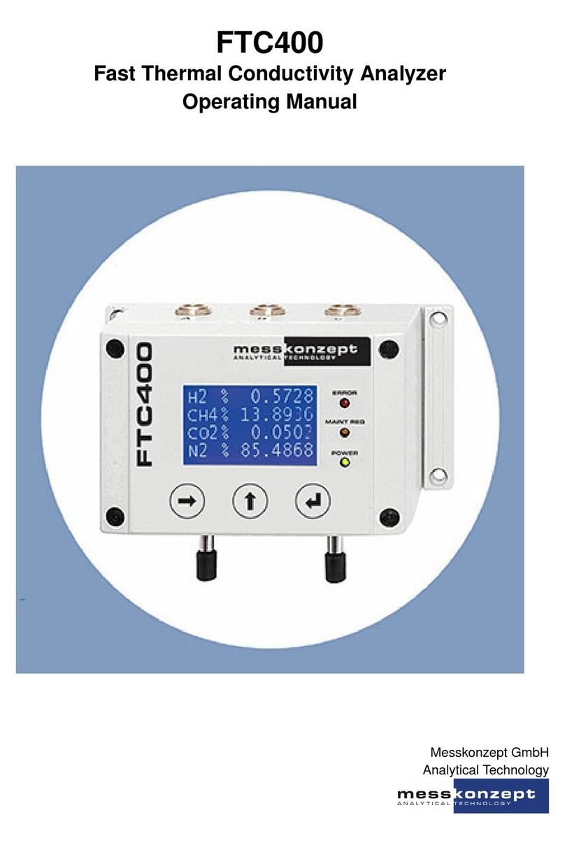
MessKonzept FTC200-OEM User manual

Filename:
FTC200_OEM_Englisch_1.09KD180125MPL1V05.docx
Seite
1 von 10
FTC200-OEM
Fast Thermal Conductivity Analyzer
Operating Manual
1.09KD180125MPL1V05© MessKonzept GmbH

Filename:
FTC200_OEM_Englisch_1.09KD180125MPL1V05.docx
Seite
2 von 10
1. Intended Use............................................................................................... 3
2. Description.................................................................................................. 4
3. EMC ........................................................................................................... 5
4. Measuring gases and ranges.......................................................................... 5
5. Scope of Delivery ......................................................................................... 5
6. Electrical Connection .................................................................................... 6
7. Pneumatic Connection.................................................................................. 7
8. Mounting .................................................................................................... 7
8.1 Thermal Insolation........................................................................................ 8
9. Communication with the FTC200-OEM .......................................................... 8
9.1. Remote Control via Serial Communication....................................................... 8
9.2. SetApp2.0................................................................................................... 9
10. Specifications ............................................................................................ 10

Filename:
FTC200_OEM_Englisch_1.09KD180125MPL1V05.docx
Seite
3 von 10
Warning!
“Warning” draws attention to application errors or actions that can lead to
safety risks including the injury to persons or malfunctions –possibly even
destruction of the device.
Note!
“Note” indicates an additional function or hint.
1. Intended Use
Only non-corrosive and condensate-,dust-, aerosol-, oil dust-free gases may
be lead in the FTC-series gas analyser. Flammable gases require
appropriate protective measures. Explosive gases may not be lead in the
FTC.
Upon installation the protection class has to be considered. The ambient
atmosphere may not be corrosive. OEM-device with protection class IP00
demand thermal and electric insulation, as well as mechanical protection
for operation.
The specifications of the device and its manual have to be observed strictly.
Please fill out questionnaire (2.01.1FB180619MPL1) for registration of
your measuring task, if your intended use does not comply with intended
use described above. Based on the information given in the questionnaire
we will examine the measuring task and possibly authorise it.
Note: Please keep this manual for future use.

Filename:
FTC200_OEM_Englisch_1.09KD180125MPL1V05.docx
Seite
4 von 10
2. Description
The FTC200-OEM is a highly precise and stable Thermal Conductivity
Detector (TCD). It is designed for the use as an OEM detector. Since it is
not equipped with housing it has protection class 00 and no electro-
magnetic shielding. It is not designed for the use in hazardous areas. As it
is true for any OEM product, all this is in the hands of our customers.
For indication of the signal a 0 to 10V analog output is provided. For
internal calibration, configuration and digital indication of the signal a TTL-
level RS232 communication is required. For testing purposes we offer a
RS232 to TTL level converter as well as two small windows programs for a
PC in order for perform Offset and Gain calibration.
The thermal conductivity of a gas mixture depends on the individual gas
components and on the composition of the mixture. Under certain
conditions, therefore, the concentration of individual gas components can
be determined by measuring the thermal conductivity. In other cases the
identification of certain properties of gases is of special interest e.g. for
quality control or safety reasons. Often these properties are related to the
thermal conductivity and thereby identified. The concentration can be
determined with high precision if one of the following conditions is met:
- The gas mixture consists of only two components, for example
measuring CO2in N2or H2inN2.
- The gas mixture consists of more than two components but only
concentrations of two components vary.
- The thermal conductivity of two of three constituents is similar, e.g.
measuring H2or He or CO2in a mixture of O2and N2.
- In case, a cross sensitive gas may be measured separately and the
signal of this measurement is fed into FTC200 where an internal
routine compensates the cross sensitivity.

Filename:
FTC200_OEM_Englisch_1.09KD180125MPL1V05.docx
Seite
5 von 10
3. EMC
The product FTC200-OEM does not meet EMC requirements without
proper shielding and housing. Means for EMC must be performed by the
customer.
4. Measuring gases and ranges
Measu-
ring
Gas
Carrier
Gas
Basic range
Smallest range
Smallest
suppressed zero
range
H2
N2or air
0% - 100%
0% - 0.5%
98% - 100%
H2
Ar
0% - 100%
0% - 0.4%
99% - 100%
H2
He
20% - 100%
20% - 40%
85% - 100%
H2
CH4
0% - 100%
0% - 0.5%
98% - 100%
H2
CO2
0% - 100%
0% - 0.5%
98% - 100%
He
N2or air
0% - 100%
0% - 0.8%
97% - 100%
He
Ar
0% - 100%
0% - 0.5%
98% - 100%
CO2
N2or air
0% - 100%
0% - 3%
96% - 100%
CO2
Ar
0% - 60%
0% - 10%
-
Ar
N2or air
0% - 100%
0% - 3%
96% - 100%
Ar
CO2
40% - 100%
-
80% - 100%
CH4
N2or air
0% - 100%
0% - 2%
96% - 100%
CH4
Ar
0% - 100%
0% - 1.5%
97% - 100%
O2
N2
0% - 100%
0% - 15%
85% - 100%
O2
Ar
0% - 100%
0% - 2%
97% - 100%
N2
Ar
0% - 100%
0% - 3%
97% - 100%
N2
CO2
0% - 100%
0% - 4%
96% - 100%
NH3
H2
0% - 100%
0% - 5%
95% - 100%
CO
H2
0% - 100%
0% - 2%
99% - 100%
SF6
N2or air
0% - 100%
0% - 2%
96% - 100%
Other gases and ranges on request.
5. Scope of Delivery
-FTC200-OEM TC-Detector
-12 pole JST-Connector with 1m open end wires
-8 pole JST-Connector with 1m open end wires
-7 pole JST-Connector with 1m open end wires
-optional: RS232-TTL-converter and PC tools for calibration

Filename:
FTC200_OEM_Englisch_1.09KD180125MPL1V05.docx
Seite
6 von 10
6. Electrical Connection
Connector X5:
Pin 01 –GND=Ground
Pin 02 –Power +24VDC = Power supply electronic, +24Volts
Pin 03 –Heater +24VDC = Power supply heater, +24Volts
Pin 04 –Heater GND
Pin 05 –GND
Pin 12 –+5VDC=+5Volts from internal voltage regulator
Connector X6:
Pin 07 –TxD-TTL = Serial TxD, TTL-level
Pin 08 –RxD-TTL = Serial RxD, TTL-level
Pin 04 –GND
Connector X7:
Pin 01 –AIn1 = Analog input, 0-10Volts, 50kOhm
Pin 02 –GND
Pin 03 –AIn2 = Analog input, 0-10Volts, 50kOhm
Pin 04 –GND
Pin 05 –AOut1 = Analog output, 0-10Volts, RL>1kOhm
Pin 07 –AOut2 = Analog output, 0-10Volts, RL>1kOhm

Filename:
FTC200_OEM_Englisch_1.09KD180125MPL1V05.docx
Seite
7 von 10
7. Pneumatic Connection
Looking at the FTC200-OEM on the side of gas tubes with the PCB up, the
gas inlet is on the right-hand side. Gas inlet and outlet tubes –as well as
the body - are stainless steel (LF316ti). The outer diameters of the tubes
are 6mm. The gas must not contain dust, condensate and potentially
condensing matter. The inner gas duct is stabilized onto 63°C (hotter
versions on demand). Depending on mounting, thermal insulation, sample
flow and temperature and ambient conditions, the temperature of the inlet
tube maybe significant lower. This fact might give reason to condensation
at dew points well below 50°C. With proper heated lines and insulated
connectors, a dew point up to 50°C is permissible.
!!! Important Notice !!!
Condensate will destroy the sensing element immediately (condensate and
dust tolerant version on request).
Optimal flow is in between 60l/h and 80l/h. If the flow is kept stable during
measurement as well as during calibration a range from 10l/h to 100l/h is
possible.
8. Mounting
The bottom view of the FTC200-OEM shows four M3 thread holes which
may be used for the fixation of the detector. Use insulating spacers (min.
4mm) and stainless-steel screws in order to minimize heat flow from the
63°C hot detector body. For bulkhead mounting two spacer and two M8
nuts are available on request.

Filename:
FTC200_OEM_Englisch_1.09KD180125MPL1V05.docx
Seite
8 von 10
8.1. Thermal Insulation
The integration the FTC200-OEM into a custom housing is mandatory,
since the device should be prevented from draught and touch for specified
performance. It may not be exposed to airflow, e.g. from fans. The use of
additional insolation is optional, but maybe necessary for ambient
temperatures below 0°C. Do not use flammable material for insulation. In
case it is in contact to the metal body, the material used must be
temperature resistant up to 120°C. It may not cover the PCBs. We
recommend an insulation material that is heat resistant up to 170°C.
The device is equipped with a temperature fuse switching off at 110°C on
the surface of the stainless-steel body.
This device is specified for an ambient temperature at direct place of
operation between -10°C to 50°C. Please consider the waste heat of other
units nearby. They may not cause a temperature enhancement.
Do not mount the device directly on a surface to prevent strong thermal
contact. Use spacers with a length of 4mm that are temperature-resistant
up to 100°C.
9. Communication with the FTC200-OEM
9.1. Remote Control via Serial Communication

Filename:
FTC200_OEM_Englisch_1.09KD180125MPL1V05.docx
Seite
9 von 10
1
www.messkonzept.de
The FTC200-OEM is equipped with a RS232-interface. A dedicated
manual is available. Please ask Messkonzept for the manual “Remote
Control via Serial Communication”.
9.2. SetApp2.0
Messkonzept offers a software for the operation of our devices. It enables
monitoring of measuring values and managing the settings of the FTC
devices. Especially for the OEM series the SetApp2.0 makes calibration,
setting thresholds and other things much easier. The SetApp2.0 can be
found on our website in the download section.1

Filename:
FTC200_OEM_Englisch_1.09KD180125MPL1V05.docx
Seite
10 von 10
10. Specifications
Dimensions with connectors;
weight
B=64mm, H=40mm,
D=75mm; ~ 350g
Power supply
24V DC (20V to 30V), 700mA
RS232 - Baudrate / Data
19200 / 8bit
Ambient temperature range
-10°C to 50°C, depending on
mounting and thermal insulation
Linearity
< 1% of range
Warm up time
Approx. 20min; 1h for small
ranges
Flow rate
10l/h-100l/h, recommended
60l/h to 80l/h
T90-time
<1sec at flow rate higher 60l/h
Noise
< 1% of smallest range
Drift at zero point
< 2% of smallest range per week
Repeatability
< 1% of range
Error due to change of ambient
temperature
< 1% of smallest range per 10°C
Error due to change of flow at
70l/h
< 1% of smallest range per
10l/h
Gas pressure (absolute)
2000kPa (20bar)
Error due to change of pressure
(above 800hPa)
< 1% of smallest range per
10hPa
Note: The values given above refer to H2 in N2, they may vary for other
gas pairs.
Table of contents
Other MessKonzept Measuring Instrument manuals
Popular Measuring Instrument manuals by other brands
Spectra Precision
Spectra Precision 5.2XL user guide

SPARLING
SPARLING Irrigation FM314 Installation, operation & maintenance manual
Extech Instruments
Extech Instruments HDV7C-A2-39-HD-1 user manual

Taylor
Taylor 13989 instruction manual
Endress+Hauser
Endress+Hauser Proline Promass O 500 PROFIBUS DP operating instructions
Time Electronics
Time Electronics 1070 user manual
