Mesto jamesbury Valv-Powr VPVL Operating and maintenance manual

Valv-Powr® VPVL
Mod D Value-Line®
Double-Opposed Piston Actuators
Installation, Maintenance and
Operating Instructions
IMO 553 EN • 5/2017

2 IMO-553 EN
READ THESE INSTRUCTIONS FIRST!
These instructions provide information about safe handling and operation of the actuator. If you require
additional assistance, please contact the manufacturer or manufacturer’s representative. Addresses and phone
numbers are printed on the back cover. See also www.metso.com/valves for the latest documentation.
SAVE THESE INSTRUCTIONS!
TABLE OF CONTENTS
1 GENERAL................................................................... 3
1.1 Warning............................................................................. 3
2 TECHNICAL DATA ..................................................... 3
3 INSTALLATION ......................................................... 4
3.1 General.............................................................................. 4
3.1 Operation ......................................................................... 4
4 MAINTENANCE......................................................... 4
4.1 General.............................................................................. 4
4.2 Disassembly..................................................................... 4
4.3 Assembly .......................................................................... 6
5 SAFETY LOCKOUT DEVICE..................................... 10
6 ACTUATOR STORAGE ............................................. 11
6 REPAIR KITS/SPARE PARTS .................................... 11
7 EXPLODED VIEW..................................................... 12
Parts list......................................................................................13
Subject to change without notice.
All trademarks are property of their respective owners.

IMO-553 EN 3
1. GENERAL
This instruction manual contains important information
regarding the installation, operation, and troubleshoot-
ing of the Jamesbury® Valv-Powr VPVL Mod D Value-Line
Double-Opposed Piston Actuators. Please read these
instructions carefully and save them for further reference.
1.1 WARNING:
1. KEEP HANDS AND CLOTHING AWAY FROM THE ACTUATOR
PINION AT ALL TIMES.
2. DO NOT ATTEMPT TO DISASSEMBLE INDIVIDUAL SPRING
CARTRIDGES. DISASSEMBLY OF THE CARTRIDGE MAY RESULT
IN SERIOUS PERSONAL INJURY. IF MAINTENANCE OF THE
CARTRIDGE IS NECESSARY, IT MUST BE RETURNED TO METSO.
3. SHUT OFF AND BLEED ALL SUPPLY LINES BEFORE
INSTALLATION OR SERVICING. DO NOT REMOVE END CAPS
WHILE THE ACTUATOR IS PRESSURIZED.
4. BEFORE INSTALLING THE VALVE AND ACTUATOR, BE SURE
THAT THE INDICATOR ON TOP OF THE ACTUATOR CORRECTLY
SHOWS THE VALVE POSITION. FAILURE TO ASSEMBLE THESE
PRODUCTS TO INDICATE THE CORRECT VALVE POSITION
COULD RESULT IN PERSONAL INJURY.
5. AN ACTUATOR MUST BE SIZED ACCURATELY FOR PROPER
OPERATION. REFER TO INFORMATION ON ACTUATOR OUTPUT
TORQUES IN A1115 OR A1114 BULLETIN AND VALVE TORQUE
REQUIREMENTS IN THE APPROPRIATE VALVE BULLETIN.
6. OPERATING THE ACTUATOR OUTSIDE OF THE PUBLISHED
TEMPERATURE LIMITS MAY DAMAGE INTERNAL AND
EXTERNAL COMPONENTS DISASSEMBLY OF SPRING RETURN
ACTUATORS MAY BE DANGEROUS.
7. OPERATING OVER THE PUBLISHED PRESSURE LIMITS MAY
RESULT IN PREMATURE FAILURE AS WELL AS DAMAGE TO THE
HOUSING.
2. TECHNICAL DATA
1. Operating Media: Dry or lubricated air, non-corrosive
and inert gas, or light hydraulic oil.
2. Air Supply: 116 psi (8 bar) Maximum.
3. Temperature:
Standard – NBR; -40° to 176°F (-40° to 80°C)
HT – Viton O-rings: 5° to 302°F (-15° to 150°C)
LX – Silicone: -60°F to 176°F (-51°C to 80°C)
4. Lubrication: Factory lubricated for the life of the actua-
tor under normal operating conditions.
5. Construction: Suitable for indoor and outdoor use.
6. External Travel Stops: -5° up +5° on the Closed posi-
tion and +5° down to -5° in the Open position.
“2” “4” “2” “4”
Double-Acting (Top View)
Air supplied to Port 2 forces pistons apart and toward end
positions with exhaust air exiting at Port 4 (a counterclockwise
rotation is obtained).
Air supplied to Port 4 forces pistons toward center with exhaust
air exiting at Port 2 (a clockwise rotation is obtained).
Figure 1
Spring-Return (Top View) Spring-to-Close
“2” “4” “2” “4”
Air supplied to Port 2 forces pistons apart and toward end
position, compressing springs. Exhaust air exits at Port 4 (a
counterclockwise rotation is obtained).
Loss of air pressure allows springs to force pistons toward center
position with exhaust air exiting at Port 2 (a clockwise rotation is
obtained).
Figure 2

4 IMO-553 EN
3. INSTALLATION
3.1 General
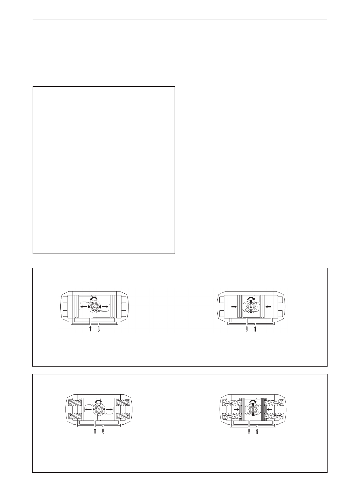
1. Check to see that the desired failure mode is correc
(Figures 1 & 2). In the spring-to-close mode, the actu-
ator will cycle clockwise to close upon loss of pressure.
If the spring-return actuator is not set up in the con-
guration desired, follow the disassembly procedure
section 4.2. Reverse the orientation of the pistons,
then reassemble following the assembly procedure,
section4.3.
2. Mount the actuator to the valve, following the direction
in the linkage AMI or valve IMO.
3. Connect a regulated air supply to the NPT tting in the
actuator housing. CAUTION: The maximum operat-
ing pressure is 116 psi (8 bar).
4. Adjust the stop screws following ASSEMBLY Section
4.3.5.
3.2 Operation
1. The actuator series, size, operating pressure, operating
temperature, output torque, spring directions, and
drive type is determined by the actuator designation.
2. The label lists the actuator series, size, operating pres-
sure, maximum pressure, and serial number.
3. Actuator designation example, VPVL300SR6BD is
a spring-return series, VPVL300 double-opposed piston
actuator that has 80-psi (5.5-bar) springs, a Teon®-
coated anodized housing (protection B), an end-of-
spring-stroke output torque of 44.9 FT•LBS (60.8 N•m).
4. MAINTENANCE
4.1 General
Although Metso’s Jamesbury actuators are designed to work
under severe conditions, proper preventative maintenance
can signicantly help to prevent unplanned downtime and
in real terms reduce the total cost of ownership. Metso rec-
ommends inspecting actuators at least every ve (5) years.
The inspection and maintenance frequency depends on the
actual application and process condition.
NOTE: All VPVL actuator fasteners are metric. Under normal
operating conditions the actuator requires only periodic
observation to ensure proper adjustment. Service kits are
available to replace seals and bearings (soft parts). These
parts are identied in (Figure 23) and listed in (Table 3).
(Table 1) below lists kit part numbers.
4.2 Disassembly
When disassembly of the actuator is required for mainte-
nance, remove the actuator from the valve. Ensure proper
lifting procedures are followed when moving or carrying
actuators. CAUTION: Do not use the M5 VDE/ VDI mount-
ing holes or the M6 hole in the pinion for lifting the
actuator.
When disassembling VPVL actuators, use caution and be
certain that the actuator is free from accessories and the air
supply is disconnected. When the actuator is a springreturn
unit, make sure that the actuator is in the failed position
before disassembling.
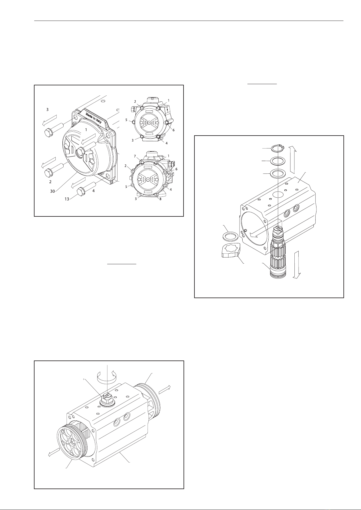
1. Removal of Position Indicator (19,20), (Figure 3):
A. Remove cap screw if tted (39).
TABLE 1
Complete Service Kit
Actuator Standard High Temp.
VPVL-01/011 RKP-152 RKP-232
VPVL-050/051 RKP-262 RKP-233
VPVL-100 RKP-263 RKP-234
VPVL-200 RKP-264 RKP-235
VPVL-250 RKP-265 RKP-236
VPVL-300 RKP-266 RKP-237
VPVL-350 RKP-267 RKP-238
VPVL-400 RKP-268 RKP-239
VPVL-450 RKP-269 RKP-240
VPVL-500 RKP-270 RKP-241
VPVL-550 RKP-271 RKP-242
VPVL-600 RKP-272 RKP-243
VPVL-650 RKP-273 RKP-244
VPVL-700 RKP-274 RKP-245
VPVL-800 RKP-275 RKP-246
39
19
Figure 3
02, 04, 03,and 11
Figure 4

IMO-553 EN 5
B. Lift position indicator (19) o shaft; it may be
necessary to pry gently with a screwdriver.
2. Removal of Stop Cap Screws (02), (Figure 4):
A. Remove both stop cap screws (02) together with
nut (04) and washer (03).
B. Remove stop screw o-rings (11) and discard if
replacing all soft parts.
3. End Cap (30) Disassembly, (Figure 5):
A. Remove the end cap bolts (13) in the sequence
shown in (Figure 5). CAUTION: When disassem-
bling a spring return actuator, the end cap (30)
should be loose after unscrewing end cap bolts
(13) 4-5 turns. If there is still force on the end cap
(30) after 4-5 turns of the end cap bolt (13), this
may indicate a damaged spring cartridge and
any further disassembly should be discontinued.
Further disassembly of the end-caps may result
in serious personal injury. Return actuator to
Metso for further maintenance.
B. For spring return actuators, remove spring cartridg-
es (17).
Figure 5
50
60
40
40
Figure 6
C. Remove end-cap o-rings (14) and discard if replacing
all soft parts.
4. Piston (40) Disassembly, (Figure 6):
A. Holding the body (50) in a vice (or similar device),
rotate the drive shaft (60) until the pistons (40)
are released. CAUTION: Air Pressure should not
be used to remove the pistons from the body.
Clean and inspect the piston teeth for signs of wear.
Replace piston if wear seems excessive.
B. Remove piston o-ring seal (16) using a screwdriver.
Remove the piston head (15) and piston back (5)
bearings. Discard bearings if replacing all soft parts.
5. Drive Shaft (60) and Bearing (6, 7) Disassembly,
(Figure 7):
A. Remove spring clip (18) carefully. Remove external
thrust bearing (8) and thrust washer (10).
B. Apply downward force to top of drive shaft (60)
until it is partially out of the bottom of the body
(50) and the octi-cam (1) and internal thrust bearing
(8) can be removed. Remove the octi-cam (1) and
internal thrust bearing (8). Push the drive shaft (60)
completely out of the bottom of the body (50). If the
shaft (60) does not move freely, gently tap with a
plastic mallet.
C. Remove the top and bottom shaft bearings (6, 7)
and top and bottom shaft o-rings (21, 22). Discard if
replacing all soft parts.
6. Cleaning and Inspection.
A. When all components are disassembled, those
not being replaced should be properly cleaned and
inspected for wear prior to re-assembly.
18
1
8
50
8
10
60
Figure 7

6 IMO-553 EN
60 50
TABLE 2
Recommended VPVL Lubricants
General Use Dow Corning type Molykote® G-2003
O-Ring Areas Dow-Corning Silicone 111
(For Standard and High Temperature)
Parker Super-O-Lube
(For LX Option)
60
6
21
20
7
Figure 8
18
8
1
1
8
10
60
60
1
50
Figure 9
4.3 Assembly
Prior to assembly, ensure that all components are clean
and undamaged.
NOTE: (Table 2) lists the recommended Valv-Powr
lubricants.
1. Drive Shaft (60) Assembly, (Figures 8 & 9):
A Install the top and bottom shaft bearings (6, 7)and
o-rings (21, 22) onto the shaft (60).
B. Apply grease to the shaft bearings (6, 7), using a gen-
eral purpose grease listed in (Table 2). Apply grease
to the shaft o-rings (21,22) using the recommended
o-ring-area grease listed in (Table 2).
C. Partially Insert the shaft (60) into the body (50).
Install the octi-cam (1) onto the shaft in the orienta-
tion shown in (Figure 9). The edges of the octi-cam
(1) should align with the edges of the square in the
bottom of the shaft (60). Insert the internal thrust
bearing (8) over the octi-cam (1). Fully insert the
shaft into the body (50).
D. Install the external thrust bearing (8), thrust washer
(10), and the spring clip (18).
2. Piston (40) Assembly, (Figures 10 through 13):
A. Install the piston o-ring seal (16) and the piston head
(15) and piston back (5) bearings.
B. Apply grease to the internal bore of the body (50)
using a recommended o-ring area grease listed in
(Table 2). Apply grease to the piston (40) rack teeth
using a recommended generalpurpose grease listed
in (Table 2).
Molykote is the registered trademark of Dow Corning
Corporations.
Figure 10

IMO-553 EN 7
C. Hold the body (50) in a horizontal position by insert-
ing the top of the shaft in a vice, or inserting the bot-
tom of the shaft connection into a male drive tted
into a vice as shown by (Figure 10).
D. Ensure that the octi-cam (1) is in the correct position
with respect to the stop screw holes as shown by
(Figure 11).
E. For standard-rotation assembly (clockwise to close)
rotate the body (50) 40 – 45° counterclockwise (if
viewing the bottom of the actuator), or clockwise (if
viewing the top of the actuator) as shown in (Figure
12).
F. Press the two pistons (40) simultaneously into the
body (50) until the piston racks are engaged and
rotate the body clockwise (if viewing the bottom of
the actuator), or counter-clockwise (if viewing the
top of the actuator), until the stroke is completed.
G. To ensure that the piston (40) teeth are evenly
engaged, fully compress both pistons (40) inward
and measure the distance from the edge of the body
to the piston (40) face on each side, shown as dimen-
sion “A” in (Figure 12). If a dierent value is obtained
on each side, remove the pistons and repeat from
step 2d.
H. Temporarily install the position indicator (19) onto
the shaft (60) to determine whether the correct
stroke is obtained, Verify that the slot in the top of
the position indicator (19) will rotate a minimum of
5° beyond the 90° vertical centerline of the actua-
tor body (50) and a minimum of 5° beyond the 0°
horizontal centerline of the actuator body as shown
in (Figure 13). If the proper stroke is not obtained,
remove the pistons and repeat from step 2d. Once
the proper stroke is veried, remove the position
indicator (19).
3. End Cap (30) and Spring Cartridge (17) Assembly,
(Figures 14 through 16):
A. For spring-return actuators, insert the proper quan-
tity of spring cartridges (17) according to the pattern
shown in (Figure 14) (referring to the total number
of springs).
AA
40°- 45°
Figure 12
Spring to Close or Clockwise to
Close for Double Acti
n
Close for Double Acting
Octi
Bottom Square
Orientation
-Cam
elohwercspotSelohwercspotS
Bottom Square
Orientation
-Cam
Spring to Open or Counterclockwise
to Open for Double Acting
Octi
elohwercspotSelohwercspotS
Figure 11 (Looking from above)
5°
Figure 13

8 IMO-553 EN
B. Apply grease to the end-cap o-ring seals, using the
recommended o-ring-area grease listed in (Table 2).
Fit the end-cap o-ring seals (14) into the groove in
each end cap (30, 31).
C. Fit the end caps (30) onto the body (50), verifying
that the o-ring seals (14) remain in the grooves.
D. Insert all end-cap screws (13) and hand tighten.
Complete tightening by following the sequence
indicated in (Figure 16), using torques listed in
Table 4.
Figure 14
17
50
4. Assembly of Stop Screws (2) and Stroke
Adjustment. (Figure 17):
A. Insert the nut (4), washer (3), and o-ring (11) onto the
stop screws (2).
B. Screw the stop screws (2) into the body (50).
5. External Travel Stop Adjustment, (Figure 17):
The stop adjustment screw (2) to the right controls the
clockwise end of travel. The stop adjustment screw (2) to
the left controls the counter-clockwise end of travel.
A. Cycle the actuator/valve to the clockwise end of
travel and measure to determine if the valve is in
the proper position. (In most applications this will be
fully closed.)
B. If the valve is not in the correct clockwise position,
turn the right stop adjustment screw (2) IN to reduce
actuator travel, or OUT to increase actuator travel.
C. When the correct clockwise position is obtained,
hold the adjusting screw (2) stationary while tight-
ening the lock nut (4).
Figure 15 2, 4, 3 and 11
Figure 17

IMO-553 EN 9
19.5
19.1
19.6
19
39
Figure 18
D. Cycle the actuator/valve to the counter-clockwise
end of travel and measure to determine if the valve is
in the proper position. (In most applications this will
be fully opened.)
E. If the valve is not in the correct counter-clockwise
position, turn the left stop adjustment screw (2) IN to
reduce actuator travel, or OUT to increase actuator
travel.
F. When the correct counter-clockwise position is
obtained, hold the adjusting screw (2) stationary
while tightening the lock nut (4).
6. Position Indicator (19, 39) Assembly. (Figure 18):
A. Fit position indicator (19) on the shaft (60), verifying
that it indicates the correct actuator position.
B. Tighten cap screw (39) to secure the position indica-
tor.
7. Setting 100% Adjustable Stop (If applicable).
(Figure 19):
To limit the rotation on the stroke beyond the standard ±5°
of a VPVL actuator, a stainless steel 100% adjustable travel
stop option can be added. The stops, located in the end
caps, allow the valve position to be set anywhere between
full closed and full open. This option limits travel of only the
counter-clockwise stroke for standard double-acting and
spring-closed units. Follow the proceeding steps in order to
set the 100% adjustable travel stops.
Figure 19

10 IMO-553 EN
Double Acting Actuators:
A. Back o one travel stop screw, leaving it partially
threaded in the end cap. Entirely remove the other
stop screw from the other end cap.
B. Open valve using air pressure. NOTE: Actuator will
leak due to removed travel stop.
C. Use the indicator pointer on top of actuator to
determine if valve is open to desired position. If not,
repeat steps 1-3, backing o or screwing in stop
screw to attain proper open position of valve.
D. Make sure O-ring is in proper position in counter-
sunk area on end cap and the washer is in place.
Tighten down nut to set stop position.
E. Thread in the other travel stop, making sure the
O-ring and washer are in the correct place. When the
travel stop will not thread any further, tighten nut to
set stop position.
F. The previous steps set the open travel stop. See
section 4.3.5 for instructions on setting the close
position stop.
Spring Return Actuators:
A. Back o one travel stop screw, leaving it partially
threaded in the end cap. Entirely remove the other
stop screw from the other end cap.
B. Open valve using air pressure. Note actuator will leak
due to removed travel stop.
C. Keeping air pressure applied to actuator, use the
indicator pointer on top of actuator to determine if
valve is open to desired position. If not, remove air
pressure and repeat steps 1-3, backing o or screw-
ing in stop screw to attain proper open position of
valve.
D. Make sure O-ring is in proper position in counter-
sunk area on end cap and the washer is in place.
Tighten down nut to set stop position.
E. Thread in the other travel stop, making sure the
Oring and washer are in the correct place. When the
travel stop will not thread any further, tighten nut to
set stop position.
F. The previous steps set the open travel stop. See
section 4.3.5 for instructions on setting the close
position stop.
5. SAFETY LOCKOUT DEVICE
WARNING:
IF THE SERIAL NUMBER OF THE ACTUATOR IS 10136023 OR LOWER
THEN THE ACTUATOR MUST BE DISASSEMBLED AND THE OCTICAM
1 MUST BE ROTATED, SEE FIGURE 9, BEFORE INSTALLING THE
SAFETY LOCKOUT KIT.
1. Removal of Stop Screws:
A. Remove from the Body both the existing Standard
Stop Screws (02) together with Nut (04), Washer (03)
and the O-ring (11), see (Figure 4).
B. Insert on the Adjustment Screw (227) and on the
Blocking Screw (226) the Special Nut (228), the
Washer (03) and the O-ring (11), see (Figure 21).
2. Assembly of Blocking Screw and Adjustment Screw:
A. Before proceeding with the assembly of the
Adjustment and Blocking Screws in the body, check
the requested stop position. If the stop position
is fully close (0°) or fully open (90°), Figure 21.
Attention: when the screws are tted,the actuator
position must be 0° ± 2° or 90° ± 2°.
Figure 20

IMO-553 EN 11
Figure 21
Figure 22
B. Insert the Blocking Screw (226) and the Adjustment
Screw (227) into the Actuator Body until the desired
lock position is achieved then tighten the Special
Nut (228), see (Figure 21).
WARNING:
THE LOCK OUT FEATURE CAN BE RENDERED INEFFECTIVE BY A
MISALIGNED OCTICAM SEE FIGURE 11 WHICH COULD CAUSE
DAMAGE TO EQUIPMENT OR PERSONAL INJURY. FUNCTIONAL
TESTING IS RECOMMENDED ON INITIAL INSTALLATION OF LOCKING
DEVICES AND AFTER ANY SERVICE OR REPAIR TO CONFIRM
EFFECTIVENESS OF THE LOCK OUT FEATURE.
C. After engaging the stop, functionally test the locked
position of the actuator by applying full pressure to
the unit against the engaged stop to conrm that
the stop is eective.
D. Insert the Blocking Screw (226) and the Adjustment
Screw (227) into the Actuator Body until the desired
lock position is achieved then tighten the Special
Nut (228), see (Figure 21).
3. Assembly of Safety Cover and Padlock:
A. Insert the Safety Cover (229) between the Special
Nuts (228) and Washer (03) as shown in (Figure 22).
B. Then insert in the hole of the Safety Cover the
Padlock (230) and lock it.
C. For safety reasons keep the Padlock key in a safe
place.
6. ACTUATOR STORAGE
If the actuators are not for immediate use, the following
precautions must be taken for storage:
A. Store in a dry environment
B. It is recommended that the actuator be stored in its
original box.
C..Do not remove the plastic plugs on the air supply-
ports.
7. SERVICE / SPARE PARTS
We recommend that actuators be directed to our service
centers for maintenance. The service centers are equipped
to provide rapid turn-around at a reasonable cost and oer
new actuator warranty with all reconditioned actuators.
NOTE: When sending goods to the service center for repair,
do not disassemble them. Clean the actuator prior to
shipping.
For further information on spare parts and service or assis-
tance visit our web-site at www.metso.com/valves.
NOTE: When ordering spare parts, always include the fol-
lowing information:
A. Actuator catalog code from label,
B. If the actuator is serialized – the serial number
(from identication plate)
C. From Figure 23, the ballooned part number, part
name and quantity required

12 IMO-553 EN
Figure 23
8. EXPLODED VIEW

IMO-553 EN 13
TABLE 3 - PARTS LIST FOR (FIGURE 23)
Part # Qty Part Description Material
1 1 Octi-Cam (Stop Arrangement) Stainless Steel / Carbon Steel (1)
2 2 Stop Cap Screw Stainless Steel
3 2 Washer (Stop Cap Screw) Stainless Steel
4 2 Nut (Stop Cap Screw) Stainless Steel
5 x 2 Bearing (Piston Back) High Grade Polymer
6 x 1 Bearing (Pinion Top) High Grade Polymer
7 x 1 Bearing (Pinion Bottom) High Grade Polymer
8 x 2 Thrust Bearing (Pinion) High Grade Polymer
9 xy 2 Plug (Transfer Port) Silicone
10 1 Thrust Washer (Pinion) Stainless Steel
11 xy 2 O-ring (Stop Cap Screw Seal) Special NBR
12 2 Piston Guide High Grade Polymer
13 8/12/16/ (2) Cap Screw (End Cap) Stainless Steel
14 xy 2 O-ring (End Cap) Special NBR
15 x 2 Bearing (Piston Head) High Grade Polymer
16 xy 2 O-ring (Piston) Special NBR
17 min. 5/ max.12 Spring (Cartridge) Alloy Steel - Epoxy Coated
18 1 Spring Clip (Pinion) Spring Steel - ENP
19.0 1 Graduated Ring High Grade Polymer
19.1 1 Position Indicator High Grade Polymer
19.5 1 Top Adaptor Extruded Aluminum - Anodized
19.6 2 Hex Socket Set Screw Stainless Steel
20 xy 1 O-ring (Pinion Bottom) Special NBR
21 xy 1 O-ring (Pinion Top) Special NBR
30 2 End Cap Cast Aluminum - Anodized - Coated
39 1 Cap Screw (Indicator) High Grade Polymer
40 2 Piston Cast Aluminum - Anodized - Coated
41 1 Actuator Identication Label Polyester Aluminum
50 1 Body Extruded Aluminum - Anodized - Coated
60 1 Drive Shaft Carbon Steel Plated
65 1 Plastic Insert High Grade Polymer
Spare parts for maintenance
x Included in Complete Kit
y Included in O-ring Kit
Notes: (1) AISI304 for models VPVL-051 through 300; Carbon Steel for models VPVL-350 through 800
(2) Qty 8 pieces for models VPVL-051 through 600; Qty 12 pieces for model VPVL-700 and Qty 16 pieces for model VPVL-800.

14 IMO-553 EN
TABLE 4
VPVL END CAP TORQUE VALUES
End Cap Metric Torque Torque Torque
Bolt Size Wrench Size in-lbs ft-lbs N-m
VPVL051 M5 8 44 53 5 6
VPVL100 M6 10 89 97 10 11
VPVL200 M6 10 89 97 10 11
VPVL250 M6 10 89 97 10 11
VPVL300 M8 13 17 18 23 24
VPVL350 M8 13 17 18 23 24
VPVL400 M10 17 35 38 47 52
VPVL450 M10 17 35 38 47 52
VPVL500 M12 19 60 63 81 85
VPVL550 M12 19 60 63 81 85
VPVL600 M14 22 97 102 132 138
VPVL650 M16 24 148 155 201 210
VPVL700 M14 22 97 102 132 138

IMO-553 EN 15
HOW TO ORDER
To specify a complete Valv-Powr Value-Line® Actuator, simply make a selection from the code boxes below.
EXAMPLE: VPVL 400 SR4/5 B AS D, shown below, is a 59 FT•LBS 60-psi (84 N•m @ 4.2 bar) spring-return actuator with
spring-to-close rotation, hard-anodized PTFE-coated body, polyester-coated end caps, standard temperature rating, and
100% adjustable travel stops.
123456
VPVL 400 SR4/5 B AS D
7
—
NOTE: for multiple options, specify them in order as listed in Item 5, for example: VPVL400 SR4/5 B HT AS Model D.
1Product Group
VPVL Valv-Powr Value-Line Double-opposed Piston Actuator
6Model
DModel D
7Modier Code
—Standard
4Exterior Protection*
BHard-Anodized PTFE-Coated Body &
Polyester-Coated End Caps
3Series+
DA Valv-Powr Value-Line Double-Acting Piston Actuator
SR4/5 Spring-Return 60-psi (4.1 bar) Spring-to-Close
(CW Rotation)
SR6 Spring-Return 80-psi (5.5 bar) Spring-to-Close
(CW Rotation)
2Size
051
Select from torque table
100,200
250,300
350, 400
450, 500
550, 600
650, 700
800
5Options
—Standard Temperature Rating: -40°F to +176°F (-40°C
to +80°C)
HT†High-Temperature Rating: +5°F to +302°F (-15°C to
+150°C)
LX*† Low-Temperature Rating: -60°F to +176°F (-51°C to
+80°C)
FO Spring-to-Open (CCW Rotation)
AS 100% Travel Stop
LD Mechanical Safety Lockout
+ Other spring rates on application
* Consult factory for other protection options.
*“LX” option must be ordered complete from the factory.
†HT and LX options decrease cycle life.

Metso Flow Control Inc.
Europe, Vanha Porvoontie 229, P. O. Box 304, FI-01301 Vantaa, Finland. Tel. +358 20 483 150. Fax +358 20 483 151
North America, 44 Bowditch Drive, P. O. Box 8044, Shrewsbury, M A 01545, USA. Tel. +1 508 852 0200. Fax +1 508 852 8172
South America, Av. Independéncia, 2500-Iporanga, 18087-101, Sorocaba-São Paulo, Brazil. Tel. +55 15 2102 9700. Fax +55 15 2102 9748
Asia Pacic, 238B Thomson Road, #17-01 Novena Square Tower B, Singapore 307685. Tel. +65 6511 1011. Fax +65 6250 0830
China, 11/F, China Youth Plaza, No.19 North Rd of East 3rd Ring Rd, Chaoyang District, Beijing 100020, China. Tel. +86 10 6566 6600. Fax +86 10 6566 2583
Middle East, Roundabout 8, Unit AB-07, P. O. Box 17175, Jebel Ali Freezone, Dubai, United Arab Emirates. Tel. +971 4 883 6974. Fax +971 4 883 6836
www.metso.com/valves
16 IMO-553
Subject to change without prior notice.
Table of contents
Other Mesto Controllers manuals
Popular Controllers manuals by other brands

Think ahead
Think ahead SR-2805ST quick start guide

Mitsubishi Electric
Mitsubishi Electric MELSEC-A Series user manual

MOTECK
MOTECK CB3T Product data sheet

Titan Controls
Titan Controls Helios 3 instruction manual

gefran
gefran 600 Installation and operation manual

Emerson
Emerson Bettis Multiport Installation, operation and maintenance manual