Met One Instruments BAM-1020 User manual

BAM 1020
PARTICULATE MONITOR
OPERATION MANUAL
BAM-1020-9800 REV G
Met One Instruments, Inc.
1600 NW Washington Blvd.
Grants Pass, OR 97526
Telephone: (541) 471-7111
Facsimile: (541) 471-7116
www.metone.com
BAM-1020 Particulate Monitor Operation Manual - © Copyright 2008 Met One Instruments, Inc. All Rights Reserved
worldwide. No part of this publication may be reproduced, transmitted, transcribed, stored in a retrieval system, or translated
into any other language in any form without the express written permission of Met One Instruments, Inc.

Table of Contents
1INTRODUCTION 4
1.1 About This Manual..................................................................................................... 4
1.2 Technical Service....................................................................................................... 4
1.3 BAM: Beta Attenuation Monitor.................................................................................. 4
1.4 Beta Radiation Safety Statement............................................................................... 5
1.5 Model BAM-1020 PM10 USEPA Equivalent Method................................................... 5
1.6 Model BAM-1020 PM2.5 USEPA Equivalent Method.................................................. 6
1.7 BAM-1020 Specifications........................................................................................... 7
2SITE SELECTION AND INSTALLATION 8
2.1 Unpacking and Inspection.......................................................................................... 8
2.2 Enclosure Selection ................................................................................................... 8
2.3 Site Selection............................................................................................................. 9
2.4 Mounting Options in a Walk-In Shelter..................................................................... 10
2.5 Installation Instructions in a Walk-In Shelter ............................................................ 11
2.6 Electrical Connections.............................................................................................. 16
3INITIAL SETUP OF YOUR BAM-1020 19
3.1 Power On................................................................................................................. 19
3.2 Warm-up .................................................................................................................. 19
3.3 Using the Keypad and Display................................................................................. 20
3.4 Filter Tape Loading.................................................................................................. 21
3.5 Self-Test................................................................................................................... 22
3.6 Initial SETUP Settings Considerations..................................................................... 23
3.7 Initial Leak Check and Flow Check.......................................................................... 24
3.8 Starting a Measurement Cycle................................................................................. 24
3.9 The Flow Statistics Screen....................................................................................... 24
3.10 The OPERATE Screen ............................................................................................ 25
3.11 The NORMAL Screen.............................................................................................. 25
3.12 The INSTANTANEOUS Screen............................................................................... 26
3.13 The AVERAGE Screen............................................................................................ 26
4THE MEASUREMENT CYCLE 27
4.1 The One-Hour Cycle Timeline.................................................................................. 27
4.2 Automatic Span Check During The Cycle................................................................ 28
4.3 Sample Period Description....................................................................................... 29
5FLOW SYSTEM and FLOW CALIBRATIONS 30
5.1 Flow System Diagram.............................................................................................. 30
5.2 Flow Type Descriptions............................................................................................ 31
5.3 Leak Check Procedure............................................................................................. 32
5.4 Leak Isolation and Nozzle Seal Methods................................................................. 33
5.5 Nozzle and Vane Cleaning....................................................................................... 33
5.6 Field Calibration of Flow System – Actual (Volumetric) Flow Mode......................... 35
5.7 Field Calibration of Flow System – EPA Standard Flow Mode................................. 36
5.8 Field Calibration of Flow System – Metered Flow Mode ......................................... 37
6SETUP MENU DESCRIPTIONS 39
6.1 CLOCK Screen ........................................................................................................ 40
6.2 SAMPLE Settings Screen – Critical Information...................................................... 40
6.3 CALIBRATE Screen – Critical Information............................................................... 42
6.4 EXTRA1 Screen....................................................................................................... 44
Page 2 BAM-1020-9800 REV G
6.5 ERRORS Screen ..................................................................................................... 45
6.6 PASSWORD Screen................................................................................................ 48
6.7 INTERFACE Screen ................................................................................................ 48
6.8 SENSOR Screen...................................................................................................... 48
6.9 HEATER Screen...................................................................................................... 50
7MAINTENANCE, DIAGNOSTICS and TROUBLESHOOTING 52
7.1 Met One Suggested Periodic Maintenance.............................................................. 52
7.2 Audit Sheet and Test Records ................................................................................. 53
7.3 Self-Test Feature ..................................................................................................... 53
7.4 Power-Up Problems................................................................................................. 53
7.5 Basic Problem and Cause/Solution Table................................................................ 53
7.6 Nozzle Component Replacement............................................................................. 56
7.7 Field BKGD Zero Background Tests........................................................................ 57
7.8 Test Menu System................................................................................................... 58
7.9 COUNT test Screen................................................................................................. 58
7.10 PUMP Test Menu..................................................................................................... 59
7.11 TAPE Test Menu...................................................................................................... 59
7.12 DAC Test Menu – Analog Output Test..................................................................... 60
7.13 CALIBRATE Test Menu........................................................................................... 60
7.14 INTERFACE Test Menu........................................................................................... 61
7.15 FLOW Test Menu..................................................................................................... 61
7.16 ALIGN Test Menu – Photo Sensor Tests................................................................. 61
7.17 HEATER Test Menu................................................................................................. 62
7.18 FILTER-T Test Menu – Filter Temperature Sensor.................................................. 62
7.19 RH Test Menu – Filter Humidity Sensor................................................................... 63
8EXTERNAL DATALOGGER INTERFACE SYSTEM 64
8.1 Analog Concentration Output Signal........................................................................ 64
8.2 Early Cycle Mode Description.................................................................................. 65
8.3 Telemetry and Error Relays ..................................................................................... 66
8.4 Digital Datalogger Interfacing with the BAM-1020.................................................... 68
9RS-232 SERIAL COMMUNICATIONS – DATA RETRIEVAL 70
9.1 Serial Port Connections and Settings....................................................................... 70
9.2 Met One Communications Software......................................................................... 71
9.3 Downloading Data Using HyperTerminal................................................................. 71
9.4 System Menu File Descriptions................................................................................ 72
9.5 Printer Output Port................................................................................................... 78
9.6 Modem Option.......................................................................................................... 79
9.7 Flash Firmware Upgrades........................................................................................ 79
10 ACCESSORIES and PARTS 80
10.1 Consumables, Replacement Parts, and Accessories............................................... 80
10.2 Series 500 Sensor Configurations............................................................................ 84
11 THEORY OF OPERATION and MATHEMATICAL ANALYSIS 86
11.1 Converting Data Between EPA Standard and Actual Conditions............................. 88
BAM-1020 Audit Sheet Sample 89
BAM-1020-9800 REV G Page 3

1 INTRODUCTION
1.1 About This Manual
This document is organized with the most important information toward the front of the
manual, such as site selection, installation, setups, and field calibrations.
Sections and sub-sections marked with an Information Symbol contain critical
information which all BAM-1020 owners and operators should read and understand. Toward
the back are sections that provide in-depth information on subjects such as theory,
diagnostics, accessories, and alternate settings. These sections provide valuable information
which should be consulted as needed. Electronic versions of this manual are also available.
1.2 Technical Service
This manual is structured by customer feedback to provide the required information for setup,
operation, testing, maintaining, and troubleshooting your BAM-1020 unit. Should you still
require support after consulting your printed documentation, we encourage you to contact
one of our expert Technical Service representatives during normal business hours of 7:00
a.m. to 4:00 p.m. Pacific Standard Time, Monday through Friday. In addition, technical
information and service bulletins are often posted on our website. Please contact us and
obtain a Return Authorization (RA) number before sending any equipment back to the
factory. This allows us to track and schedule service work and expedite customer service.
Phone: (541) 471-7111 Fax: (541) 471-7116
Address: Technical Services Department
Met One Instruments, Inc.
1600 NW Washington Blvd.
Grants Pass, OR 97526
1.3 BAM: Beta Attenuation Monitor
The Met One Instruments model BAM-1020 automatically measures and records airborne
particulate concentration levels using the principle of beta ray attenuation. This method
provides a simple determination of concentration in units of milligrams or micrograms of
particulate per cubic meter of air. A small 14C (Carbon 14) element emits a constant source of
high-energy electrons known as beta particles. These beta particles are detected and
counted by a sensitive scintillation detector. An external pump pulls a measured amount of
dust-laden air through a filter tape. After the filter tape is loaded with ambient dust, it is
automatically placed between the source and the detector thereby causing an attenuation of
the beta particle signal. The degree of attenuation of the beta particle signal is used to
determine the mass concentration of particulate matter on the filter tape, and hence the
volumetric concentration of particulate matter in ambient air. A complete description of the
measurement cycle is included in Section 4. In addition, an in-depth scientific explanation of
the theory of operation and the related equations is included toward the back of the manual.
Page 4 BAM-1020-9800 REV G

1.4 Beta Radiation Safety Statement
The Met One Instruments BAM-1020 contains a small 14C (Carbon 14) beta radiation-emitting
source. The activity of the source is 60 µCi ±15µCi (microcurries), which is below the “Exempt
Concentration Limit” as defined in 10 CFR Section 30.70 – Schedule A. The owner of a BAM-
1020 is not required to obtain any license in the United States to own or operate the unit. The
owner of a BAM-1020 may elect to return the entire unit to Met One Instruments for recycling
of the 14C source when the unit has reached the end of its service life, although the owner is
under no obligation to do so. Under no circumstances should anyone but factory technicians
attempt to remove or access the beta source. The beta source has a half-life of about 5730
years, and should never need to be replaced. Neither the 14C source nor the beta particle
detector are serviceable in the field. Should these components require repair or replacement,
the BAM-1020 must be returned to the factory for service and recalibration.
1.5 Model BAM-1020 PM10 USEPA Equivalent Method
The Met One Instruments, Inc. Model BAM-1020 is designated as an equivalent method for
PM10 monitoring by the United States Environmental Protection Agency on August 3, 1998.
Designation Number: EQPM-0798-122
The EPA designation applies to G, -1, G-1, and later BAM-1020 PM10 Beta Attenuation
Monitors, when used in conjunction with the following requirements. Users are advised that
configurations that deviate from this specific description may not meet the applicable
requirements of 40 CFR Parts 50 and 53.
•The BAM-1020 is operated to obtain a daily average of the hourly measurements, with
a filter change frequency of one hour.
•The inlet must be equipped with the standard BX-802 EPA PM10 inlet head.
•The unit must be used with standard glass fiber filter tape.
•The unit may be operated with or without any of the following options: BX-823 inlet
tube extension, BX-825 heater kit, BX-826 230V heater kit, BX-828 roof tripod, BX-902
exterior enclosure, BX-903 exterior enclosure with temperature control, BX-961 mass
flow controller, BX-967 internal calibration device.
•The SAMPLE TIME parameter must be set for 50 minutes.
BAM-1020-9800 REV G Page 5

1.6 Model BAM-1020 PM2.5 USEPA Equivalent Method
The Met One Instruments, Inc. Model BAM-1020 Beta Attenuation Mass Monitor - PM2.5 FEM
Configuration, is designated as an equivalent method for PM2.5 monitoring in accordance with
40 CFR Part 53 by the United States Environmental Protection Agency as of March 12, 2008.
Designation Number: EQPM-0308-170
All of the following parameters and conditions must be observed when the BAM-1020 is
operated as a PM2.5 FEM particulate monitor:
•The inlet must be equipped with an EPA-designated PM2.5 Very Sharp Cut Cyclone
(VSCC™-A by BGI, Inc.). The Met One stock number for the VSCC™ is BX-808.
•The inlet must be equipped with a standard EPA PM10 inlet head. Met One BX-802.
•The unit is operated for hourly average measurements. The PM2.5 concentration is
calculated (external to the BAM) as a daily average of the hourly concentration
measurements made by the BAM-1020.
•The unit must be equipped with firmware revision 3.2.4 or later.
•The BAM-1020 must be operated in proper accordance with this operation manual,
revision F or later. A supplemental BGI Inc. manual is also supplied with the VSCC™.
•The unit must be equipped with a BX-596 ambient temperature and barometric
pressure combination sensor. This is used for flow control and flow statistics.
•The unit must be equipped with the internal BX-961 automatic flow controller, and
must be operated in Actual (volumetric) flow control mode.
•The unit must be equipped with a BX-827 (110V) or BX-830 (230V) Smart Inlet Heater,
with the heater RH regulation setpoint set to 35%, and Delta-T control disabled.
•The unit must be equipped with the 8470-1 rev D or later tape control transport
assembly with close geometry beta source configuration. All BAM-1020 units
manufactured after March 2007 have these features standard. Older units will have to
be factory upgraded and re-calibrated to the latest specifications.
•The unit must be operated with standard glass fiber filter tape.
•The COUNT TIME parameter must be set for 8 minutes.
•The SAMPLE TIME parameter must be set for 42 minutes.
•The BX-302 zero filter calibration kit is a required accessory. This kit must be used to
audit the BKGD (background) value upon unit deployment and periodically thereafter,
as described in the BX-302 manual.
•The unit may be operated with or without a BX-823 eight foot inlet tube extension and
with or without weatherproof outdoor enclosures BX-902 or BX-903.
Page 6 BAM-1020-9800 REV G

1.7 BAM-1020 Specifications
PARAMETER SPECIFICATION
Measurement Principle: Particulate Concentration by Beta Attenuation.
US-EPA Existing
Designations:
PM10: EPA EQPM-0798-122
PM2.5: Class III EPA EQPM-0308-170
Standard Range: 0 - 1.000 mg/m3(0 - 1000 µg/m3)
Optional Ranges: 0 - 0.100, 0.200, 0.250, 0.500, 2.000, 5.000, 10.000 mg/m3(special applications)
Accuracy: Exceeds US-EPA Class III PM2.5 FEM standards for additive and multiplicative bias.
Resolution: ± 0.1 µg/m3
Lower Detection Limit:
(2σ) (1 hour)
Less than 4.8 µg/m3from 0.000 to 0.100 mg/m3(less than 4.0 µg/m3 typical)
Lower Detection Limit:
(2σ) (24 hour)
Less than 1.0 µg/m3
Measurement Cycle Time: 1 Hour
Flow Rate: 16.7 liters/minute. Adjustable 0-20 LPM range. Actual or Standard flow.
Filter Tape: Continuous glass fiber filter, 30mm x 21m roll. > 60 days/roll.
Span Check: Automatic 800ug (typical) span foil verified hourly.
Beta Source: 14C (carbon-14), 60 µCi ±15 µCi (< 2.22 X 10⁶Beq), Half-Life 5730 years.
Beta Detector Type: Photomultiplier tube with organic plastic scintillator.
Operating Temp. Range: 0 to +50°C
Ambient Temp. Range: -30° to +60°C
Ambient Humidity Range: 0 to 90% RH, non-condensing.
Humidity Control: Actively controlled inlet heater module, 10 - 99% RH setpoint.
Approvals: US-EPA, CE, NRC, TUV, CARB, ISO-9001
User Interface: Menu-driven interface with 8x40 character LCD display and dynamic keypad.
Analog Output: Isolated 0-1 VDC output standard. 0-10V, 4-20mA, 0-16mA switch-selectable.
Serial Interface: RS-232 2-way serial port for PC or modem communications.
Printer Output: Output-only serial port, data or diagnostic output to a PC or serial printer.
Telemetry Inputs: Clock Reset (voltage or contact closure), Telemeter Fault (contact closure).
Alarm Contact Closures: Data Error, Tape Fault, Flow Error, Power Failure, Maintenance.
Compatible Software: MicroMet Plus®, Comet™, HyperTerminal®, ProComm Plus®.
Error Reporting: User-configurable. Available through serial port, display, and relay outputs.
Memory: 4369 records (182 days @ 1 record/hr).
Power Supply: 100 - 230 VAC, 50/60 Hz. 0.4 kW 3.4A max.
Weight: 24.5 kg (54 lbs) without external accessories.
Unit Dimensions: H x W x D = 31cm x 43cm x 40cm (12.25” x 17” x 16”).
*Specifications may be subject to change without notice.
BAM-1020-9800 REV G Page 7

2 SITE SELECTION AND INSTALLATION
2.1 Unpacking and Inspection
If any damage to the shipment is noticed before unpacking, a claim must be filed with the
commercial carrier immediately. Notify Met One Instruments after notification of the
commercial carrier.
Remove the unit and accessories from the shipping boxes and compare the received items to
the packing list. Make sure you have all of the required items for the type of installation you
plan to perform.
The BAM-1020 is shipped with two white foam rings and a white plastic shim inside the front
of the unit, which prevent the moving parts of the tape control assembly from being damaged
in transit. Do not remove the foam rings until the BAM-1020 is ready to be installed. These
rings must be replaced anytime the unit is being transported in order to avoid damaging the
tape control mechanism.
Please keep the special box and foam packing material that the BAM-1020 was shipped in, to
re-use in the event that you must return the unit to the factory. Met One is not responsible for
any damages to the unit if returned in non-original packaging, or without the foam rings in
place. Contact Met One for replacement packing materials if necessary.
2.2 Enclosure Selection
The BAM-1020 unit is not weatherproof or water resistant, and is designed to be mounted in
a weatherproof, level, vibration free, dust free, and temperature controlled environment where
the operating temperature is between 0oC and +50o C, and where the relative humidity is
non-condensing and does not exceed 90%. There are two standard configurations described
below for providing a weatherproof location in which to install the unit. Please contact Met
One if you plan to have a non-standard mounting or enclosure configuration.
1. A walk-in building or mobile shelter with a flat roof: This is often a pre-fabricated
shelter, a trailer shelter, or a room in an existing permanent building. The BAM is
mounted on a bench-top or in an equipment rack, often with a variety of other
instruments installed in the same shelter. The inlet tube of the BAM must extend up
through the roof with appropriate hardware. AC power must be available. Instructions
for this type of installation are included in this section of the manual.
2. BX-902/903 environmentally controlled mini enclosure: Sometimes nicknamed
“dog house” enclosures, these small pre-fabricated enclosure are just big enough for
the BAM and related accessories, and are installed on the ground or on the roof of a
larger building. They are available with a heater (BX-902), or with a heater and air
conditioner (BX-903). These enclosures are custom designed by Met One to accept
the BAM-1020, and are supplied with a supplemental setup and installation manual.
NOTE: The air temperature inside any enclosure in which a BAM-1020 is installed must be
held as constant as possible over the course of the hour. This is important because the unit
measures the beta particles through a small gap of air around the filter tape at the beginning
and the end of each hour. If the air temperature inside the enclosure has changed by more
Page 8 BAM-1020-9800 REV G

than about 2 degrees C during this time, the concentration measurement can be affected on
the order of several micrograms. Met One recommends logging the air temperature inside the
enclosure to monitor this effect. The exact temperature is not critical as long as it fluctuates
as little as possible during any one hour.
2.3 Site Selection
Selection of a proper site for the BAM-1020 is critical for accurate measurements. In many
cases, these items must be correctly addressed in order for the collected data to be
acceptable for regulatory requirements, such as EPA PM10 and PM2.5 equivalent methods.
Specifications for the site selection can be found in EPA document EPA-450/4-87-007 May
1987 “Ambient Monitoring Guidelines for Prevention of Significant Deterioration”, as well as
40 CFR, Part 58. In any case, the Code of Federal Regulations takes precedence.
Inlet Height:
•The inlet should be located in the “breathing zone”, between 2 and 15 meters above
ground level. If the BAM is to be installed in an enclosure at ground level, then the inlet
height must two meters or greater above the ground.
•If the inlet is located on (or through) a rooftop, the total height should be no more than
15 meters from the ground level. The inlet height should be two meters above roof
surface of the building that the unit is installed in. This matches the specified inlet
height of most FRM samplers.
•If the BAM-1020 is to be co-located with other particulate instruments, such as FRM
filter-based samplers or other BAM units, then the air inlet must be the same height as
the inlet of the other samplers.
•The BX-902 and BX-903 environmental shelters are designed to locate the inlet two
meters above whatever surface they are placed on.
•Make sure to account for the height of the PM10 and/or PM2.5 heads when planning the
inlet tube length. Met One can supply a variety of tube lengths up to 8-feet long.
•The maximum allowable total inlet tube length is 16 feet between the BAM-1020 and
the bottom of the inlet head.
•If the BAM inlet is the highest point on a building, then lightning rods must be installed
to prevent destruction of the BAM during electrical storms.
Inlet Radius Clearance:
•The BAM-1020 inlet must have a one meter radius free of any objects that may
influence airflow characteristics, including the inlet of another instrument.
•If a BAM-1020 is to be installed at a station with other BAM or FRM sampler, the inlets
of each sampler must be no less than one meter apart from each other.
•If the BAM is to be collocated with another BAM instrument or FRM sampler, then the
inlets must be spaced between one and two meters apart. Two meters is
recommended where possible.
•If installing near a PM10 SSI Hi-Volume sampler, then the distance between the inlet of
the BAM-1020 and the Hi-Vol should be no less than three meters.
•The BAM-1020 inlet must be located at least two meters from obstructions such as
short walls, fences, and penthouses.
•If located beside a major obstruction (such as a building) then the distance between
the unit and the building must be equal to twice the height of the building.
BAM-1020-9800 REV G Page 9

•The inlet must be at least 20 meters from the drip line of any overhanging trees.
•There must be at least a 270 degree arc of unrestricted airflow around the inlet. The
predominant direction of concentration movement during the highest concentration
season must be included in the 270 degree arc.
Particulate Sources: To avoid possible errors in the concentration measurements, the inlet
must be located as far as possible from any artificial sources of particulate, such as blowers,
vents, or air conditioners on a rooftop. Especially if any of these types of devices blow air
across the inlet of the BAM-1020. Even sources of filtered air must not blow across the inlet.
Spacing from Roadways: The BAM-1020 should usually not be located directly next to a
major highway or arterial roadway, as vehicle exhaust will dominate the concentration
measurement. This effect can be difficult to predict accurately as shifting winds may direct the
plume toward or away from the BAM inlet.
•Roads with a daily traffic volume of less than 3,000 vehicles are generally not
considered major sources of pollutants, and in this case the BAM must be located at
least five meters from the nearest traffic lane.
•The BAM must be located at least 25 meters from any elevated roadway greater than
five meters high.
•The unit should be located as far as possible from unpaved roadways, as these also
cause artificial measurements from fugitive dust.
•The unit should not be installed in unpaved areas unless year-round vegetative ground
cover is present, to avoid the affects of re-entrained fugitive dust.
2.4 Mounting Options in a Walk-In Shelter
When the BAM-1020 is to be located in a walk-in shelter, the unit will have to be installed
either in an equipment rack or on a bench-top. Met One recommends using an equipment
rack when possible, as it does a better job of keeping the unit level and in the correct
placement. A rack also tends to be a cleaner installation and is more space-efficient.
However, either method may be used as long as the mounting is level and allows the inlet
tube to be perfectly vertical. Met One supplies brackets standard rack-mount screws with
each unit. Take the following into account when planning your mounting:
•Rear Access: It is important that your mounting leaves plenty of access to the rear of
the BAM-1020 unit for wiring connections and maintenance. At least five inches is
required. Full access to the back is recommended whenever possible.
•Top Access: It is necessary to have a minimum of eight inches clearance between
the top of the BAM inlet receiver and the bottom of the shelter ceiling to accommodate
the smart inlet heater which mounts on the inlet tube directly above the BAM.
•Mobile Shelters: If the BAM-1020 is being installed into an equipment rack in a
mobile shelter or van, the instrument must be supported from the bottom in addition to
the rack brackets, due to additional strain. The foam shipping rings must also be
inserted any time a mobile shelter is moved with the BAM-1020 inside.
•Rack Modifications: It is often necessary to modify the top of the equipment rack by
cutting a hole to allow the inlet tube to extend through to the ceiling. The drawing
below shows the location of the hole. Note: The inlet heater is a cylinder which installs
Page 10 BAM-1020-9800 REV G

on the inlet tube two inches above the top of the inlet receiver of the BAM-1020. If the
BAM unit is to be mounted high in the rack, it may be necessary to make the hole in
the top of the rack larger in order to clear the heater diameter. The heater is supplied
with an insulation tube cover which may be modified as needed. Make sure these
parts are going to fit before installing the BAM-1020.
Rack top modifications for inlet tube clearance
2.5 Installation Instructions in a Walk-In Shelter
Installation of the BAM-1020 should be performed by personnel familiar with environmental
monitoring equipment. There are no special precautions or handling concerns except for the
normal level of care required for handling scientific equipment. Refer to the diagrams on the
following pages.
1. Roof Modifications: Determine the exact location where the BAM inlet tube will pass
through the roof of the enclosure, and drill a 2 ¼” or 2 ½” diameter hole through the
roof at that location. Make sure the hole is directly above where the BAM inlet receiver
is to be located, as the inlet tube must be perfectly vertical. A plumb-bob is useful for
determining where to locate the hole. Note: The inlet receiver on the BAM is slightly to
the left (0.6 in, 15 mm) of the center line of the unit. See diagrams.
2. Waterproof Flange: Apply all-weather caulking around the top of the hole, and install
the BX-801 roof flange onto the hole. It is usually best if the threaded barrel of the
flange assembly is installed downward, into the hole. Secure the flange in place with
four lag bolts or self-tapping screws (not supplied). Caulk around the screws to prevent
leaks. Apply Teflon tape to the threads of the gray plastic watertight fitting, and screw it
into the roof flange.
3. Inlet Tube: Remove the white cap and rubber seal from the flange assembly. This
makes it easier to install the inlet tube, as the rubber seal is a tight fit around the tube.
Lower the inlet tube through the flange assembly in the roof and into the inlet receiver
on the BAM Make sure the inlet tube is fully seated.
4. Inlet Alignment: It is very important for the inlet tube to be perpendicular to the top of
the BAM. The nozzle may not close properly if there is binding caused by
misalignment. A simple check is to rotate the inlet tube back and forth by hand (before
BAM-1020-9800 REV G Page 11

tightening the roof flange seal or the BAM inlet set screws). If the inlet tube is installed
straight, then the tube should rotate fairly easily while inserted into the BAM. If it does
not rotate, check the inlet tube for vertical alignment or move the BAM slightly.
5. Smart Heater: Before tightening the inlet tube in place, the BX-827 or BX-830 smart
inlet heater (used on most BAM-1020 units) must be installed on the tube. Pull the inlet
tube up out of the inlet receiver, and pass the tube through the hole in the heater body
(the cable end is the bottom). Then re-insert the inlet tube into the BAM. Position the
bottom of the heater unit two inches above the top of the inlet receiver on the BAM,
and securely tighten the two set screws in the heater to fasten it to the tube. Included
with the smart heater is a 12” tube of insulation. The tube is split down its length for
easy application. Wrap the insulation around the heater body and peel back the
adhesive cover strip to secure in place. The insulation may be cut to fit if needed.
6. Inlet Tightening: Slide the black rubber seal and white cap down over the top of the
inlet tube and into the roof flange. It is easier if you wet the rubber seal with water or
alcohol first. Tighten the white plastic cap.
7. Support Struts: The BX-801 inlet kit usually comes with two angled aluminum struts
to support the inlet tube above the roof and prevent the inlet from moving in the wind.
These struts are typically fastened (about 90 degrees apart) to the inlet tube with a
supplied hose clamp. The bottom ends of the struts should be fastened to the roof with
lag bolts (not supplied). Note: Some installations may require different methods or
hardware for supporting the inlet tube. Support the tube in the best manner available.
8. Temperature Sensor: Most BAM-1020 units are supplied with a BX-592
(temperature) or BX-596 (temperature and pressure) sensor, which is attached to the
inlet tube above the roof. The sensor cable must feed into the shelter to be attached to
the BAM. In some cases it is easiest to simply drill a 3/8” hole through the roof about
six inches away from the inlet tube, then feed the cable through the hole and caulk
around it to prevent leaks. In some applications there may be a better place to feed the
cable into the shelter. Route the cable into the shelter in the best manner. The BX-596
attaches directly to the inlet tube with a supplied U-bolt. If using a BX-592, fasten the
aluminum cross-arm to the inlet tube, and clip the temperature probe to the cross-arm.
9. Inlet Separator Heads: If the BAM-1020 is to be configured for FEM PM2.5 monitoring,
then install the PM2.5 Very Sharp Cut Cyclone (BGI VSCC™) onto the top of the inlet
tube beneath the BX-802 PM10 head. For PM10 monitoring, the BX-802 is installed on
the inlet tube with no cyclone. Use o-ring lubricant as needed.
10.Inlet Tube Grounding: Tighten the two ¼”-20 set screws located in the inlet receiver
of the BAM to secure the inlet tube. This also creates a ground connection for the inlet
tube, as static electricity can build up on the inlet under certain atmospheric conditions
and cause errors. This is very important in areas near electromagnetic fields, high
voltage power lines, or RF antennas. Check the connection by scraping away a small
spot of the clear anodizing near the bottom of the inlet tube, and use a multimeter to
measure the resistance between this spot and the “CHASSIS” ground connection on
the back of the BAM. It should measure just a couple of Ohms or less if a good
connection is made with the set screws. If not, remove the set screws and run a ¼-20
tap through the holes. Then reinstall the screws and check the electrical resistance
again. Note: Anodized aluminum surfaces are non-conductive.
Page 12 BAM-1020-9800 REV G

BAM-1020-9800 REV G Page 13
BX-802
PM10 Head adds
14.0” adds
19.0”
BX-808
BGI VSCC™
PM2.5 Cyclone
(optional)
BX-596
AT/BP Sensor
(or BX-592)
2 Meters
Inlet Support
Struts
6.5 feet
8112
Inlet Tube
8’ standard
BX-801
Roof Flange
Enclosure
Roof
BX-827 or 830
Smart Heater
with insulation
Mounting
Bench or Rack
2”
BAM-1020
With Medo
vacuum pump
or equivalent
8” min. clearance
3 to 4 feet typical
5’ typical
3/28/2007 BAM 1020 16:08:29
LAST CONCENTRATION: 0.028 mg/m3
CURRENT FLOW: 16.7 LPM
STATUS: ON
FIRMWARE: 3236-02 3.2.4
SETUP OPERATE TEST TAPE
F1 F2 F3
F4 F5 F6
BAM 1020
MET ONE INSTRUMENTS
Typical BAM-1020 Installation in a walk-in shelter

3/28/2007 BAM 1020 16:08:29
LAST CONCENTRATION: 0.028 mg/m3
CURRENT FLOW: 16.7 LPM
STATUS: ON
FIRMWARE: 3236-02 3.2.4
SETUP OPERATE TEST TAPE
BX-802
Page 14 BAM-1020-9800 REV G
PM10 Head
F1 F2 F3
F4 F5 F6
BAM 1020
MET ONE INSTRUMENTS
adds
14.0” adds
19.0”
BX-808
BGI VSCC™
PM2.5 Cyclone
(optional)
BX-596
AT/BP Sensor
(or BX-592)
Inlet Tube
2”
-Total Height-
6.6 ft (2.0 meters)
without cyclone
7.0 ft (2.1 meters)
with cyclone
15.5”
27” typical
Inlet tube
8119 Seal
BX-827 or 830
Smart Heater
with insulation
Mounting
Rack
BX-902/903
Environmental
Enclosure
BX-126
Vacuum Pump
or equivalent
Typical BAM-1020 Installation in a BX-902 mini enclosure

BAM-1020-9800 REV G Page 15
12.25” 3/28/2007 BAM 1020 16:08:29
LAST CONCENTRATION: 0.028 mg/m3
CURRENT FLOW: 16.7 LPM
STATUS: ON
FIRMWARE: 3236-02 3.2.4
SETUP OPERATE TEST TAPE
F1 F2 F3
F4 F5 F6
BAM 1020
MET ONE INSTRUMENTS
14.25”
19”
17”
120 VOLTS
5” min. rear clearance CL
TOP
16”
75mm (2.95”)
from front face
15mm (0.6”)
from center
9.25”
3.5”
FRONT BACK
BAM-1020 mounting dimensions

2.6 Electrical Connections
Each BAM-1020 is factory configured to run on either 120 or 230 volt AC power. Your shelter
must be wired for power to run the BAM, the pump, and any other AC powered devices such
as computers, data loggers, other instruments, etc. A good earth-ground connection point
near the BAM unit is highly recommended. Have a qualified electrical contractor provide
power according to all local codes. After the BAM unit is installed and power is provided,
connect the electrical accessories as follows. Refer to the diagram below.
1. BAM-1020 Power: Plug the BAM-1020 into the AC power mains with the provided
power cord. Note: There are two fuses located inside the BAM power switch module,
which can be accessed by prying open the small cover surrounding the switch. The
power cord must be removed in order to open the cover.
Met One recommends plugging the BAM-1020 unit into a battery back-up UPS
(uninterruptible power supply) since even a momentary power outage will reset the
BAM and stop an entire hour’s worth of data collection. A small computer-style UPS of
300 Watts or greater is usually sufficient. The vacuum pump usually does not need to
be connected to the UPS as the BAM can compensate for short pump power outages.
If the pump is to be backed up as well, then a much larger UPS is required.
2. Chassis Ground: Connect one of the terminals marked “CHASSIS” on the back of the
BAM to a ground point as close as possible to the instrument. Use the green/yellow
ground wire supplied with the unit. A ground rod is recommended, but a cold water
pipe, or junction box safety ground are other possible connection points. Note: the
BAM-1020 also uses the standard safety ground line inside the power cord.
3. Pump Connection: Decide on a location to place the air pump. The best location is
often on the floor under the rack or bench, but it may be up to 25 feet away if desired.
Route the air tubing from the pump to the back of the BAM unit, inserting it firmly into
the compression fittings on both ends. The tubing should be cut to the proper length
and the excess saved for replacements. The pump is supplied with a 2-wire signal
cable which the BAM uses to turn the pump on and off. Connect this cable to the
terminals on the back of the BAM marked “PUMP CONTROL” The end of the cable
with the square black ferrite filter goes to the BAM, but the polarity of the wires is not
important. Either the red or black wire can go to either terminal. Connect the other end
of the cable to the two terminals on the pump.
4. Temperature/Pressure Sensor: The BX-596 or BX-592 temperature sensor should
already be installed onto the inlet tube, and the sensor cable routed to the BAM-1020.
Connect the cable to the terminals on the back of the BAM as follows:
BX-596 AT/BP Sensor
Wire Color Terminal Name
Yellow Channel 6 SIG
Black/Shield Channel 6 COM
Red Channel 6 POWER
Green Channel 6 ID
White Channel 7 SIG
Page 16 BAM-1020-9800 REV G

BX-592 AT Sensor
Wire Color Terminal Name
Yellow or White Channel 6 SIG
Black/Shield Channel 6 COM
Red Channel 6 POWER
Green Channel 6 ID
Additional Met One BX-500 series sensors may be connected to BAM channels 1
through 5 to log various other meteorological parameters. Details on these sensor
connections are given in Section 10.2 of this manual.
5. Smart Heater: There are two possible versions of the BX-827/830 Smart Heater
electrical connection. If the Smart Heater kit was supplied with a gray relay module
(units built after May, 2008 as shown below), then plug the relay module into the
mating control connector on the back of the BAM, and connect the Smart Heater to the
green connector on the top of the relay module. The relay module has its own power
cord to supply power to the heater. Note: The connector on the back of the BAM has
been changed to prevent connecting the heater directly to the BAM.
On previous versions of the kit, the Smart Heater assembly simply plugs directly into
the back of the BAM-1020, and power is supplied internally by the BAM. If the BAM is
configured like this, then simply plug the heater cable directly into the mating green
metal connector on the back of the BAM-1020.
Smart Heater
Relay Module
Heater Power Cord
6. Optional Data Logger Connection: The BAM-1020 has an analog output which may
be recorded by a separate data logger if required. Connect the terminals on the back
of the BAM marked ”VOLT OUT +, -“ to the data logger with 2-conductor shielded
cable (not supplied). Polarity must be observed. Information on configuring this analog
output is provided in Section 8 of this manual. A current loop output is also available.
7. Other Connections: The BAM-1020 has a variety of telemetry I/O relays and error
relays located on the back of the unit. There are also RS-232 data connections. These
items are described in Section 8 and Section 9 of this manual.
BAM-1020-9800 REV G Page 17

RANGE
X1
PRINTER
RS-232
OPTION
SWITCH
1 2 3 4
TELEMETRY
FAULT N.V.
SIG
COM
POWER
ID
CHAN 1
SIG
COM
POWER
ID
SIG
COM
POWER
ID
SIG
COM
POWER
ID
SIG
COM
POWER
ID
SIG
COM
POWER
ID
SIG
COM
POWER
ID
SMART
HEATER
EXTERNAL
RESET N.V.
+
EXTERNAL
RESET V.
-
TAPE
FAULT
INVALID
DATA
MAINTENANCE
FLOW
FAULT
PUMP
CONTROL
POWER
FAIL
+
VOLTAGE
OUTPUT
-
CHASSIS
GROUNDS
+
CURRENT
OUTPUT
-
CHAN 2
CHAN 3
CHAN 5
CHAN 6
CHAN 7
CHAN 4
RANGE
X10
SW1 OFF= 0-1V
SW1 ON= 0-10V
SW2 OFF= 0-16mA
SW2 ON= 4-20mA
RS232
POLARITY
C1 NORMAL
C2 REVERSE
V
ACUUM
BAM-1020 back panel connections
Page 18 BAM-1020-9800 REV G

3 INITIAL SETUP OF YOUR BAM-1020
This section describes the process for setting up and configuring your BAM-1020, as well as
the basic steps required to put the unit into operation. Some of the topics in this section will
direct you to other sections of this manual for more detailed information. It is assumed that
the unit is already installed and sited as described in Section 2. In some cases it is useful to
first set up the BAM-1020 unit on a test bench before deployment or installation in order to
explore the functions of the unit and perform setups. The following steps for starting up your
unit are described in this section:
1. Power on and warm up the unit.
2. Familiarize yourself with the user interface.
3. Load a roll of filter tape.
4. Perform a Self-Test.
5. Set the real-time clock, and review your SETUP parameters.
6. Perform a leak check and a flow check.
7. Return to the top-level menu and wait for automatic start at the top of the hour.
8. View the OPERATE menus during the cycle.
3.1 Power On
The BAM-1020 has a power switch located on the back of the unit directly above the power
cord. Verify that the unit is plugged in to the correct AC voltage, and that any electrical
accessories are correctly wired before turn the unit on. (Section 2.6) When power is switched
on the main menu screen should appear after a few seconds as shown below. The unit will
probably flash an error indicating that there is no filter tape installed. Note: Units running
revision 3.1 or earlier firmware will display a slightly different main menu screen.
3/28/2007 BAM 1020 16:08:29
LAST CONCENTRATION: 0.028 mg/m3
CURRENT FLOW: 16.7 LPM
STATUS: FILTER TAPE ERROR!
FIRMWARE: 3236-02 3.2.4
SETUP OPERATE TEST TAPE
The Main Menu Screen
3.2 Warm-up
The BAM-1020 must warm up for at least one hour before an operation cycle is started. This
is because the beta detector contains a vacuum tube which must stabilize every time the unit
is powered up. This also allows the electronics to stabilize for optimal operation. This applies
any time the unit is powered up after being off for more than a moment. Instrument setups
and filter tape installation can be performed during this warm up time. Most agencies choose
to discard the first few hours of concentration data after the BAM is powered up.
BAM-1020-9800 REV G Page 19

3.3 Using the Keypad and Display
When the BAM-1020 is powered up it will display the main (top level) menu on the LCD
display. This menu is the starting point for all functions of the BAM-1020 user interface.
3/28/2007 BAM 1020 16:08:29
LAST CONCENTRATION: 0.028 mg/m3
CURRENT FLOW: 16.7 LPM
STATUS: ON
FIRMWARE: 3236-02 3.2.4
SETUP OPERATE TEST TAPE
F1 F2 F3
F4 F5 F6
The BAM-1020 User Interface
Soft Keys:
Directly beneath the display are four white buttons called “soft-keys” or “hot-keys”. These are
dynamic keys who’s function changes in response to a menu option displayed directly above
each key on the bottom row of the display. Whatever menu option is displayed above one of
these keys is the function which that key will perform in that particular menu. These are used
throughout the entire menu system for a wide variety of functions. For example, modifications
made within a menu are usually not saved unless a SAVE soft-key is pressed. EXIT is also
another common soft-key function.
Arrow (Cursor) Keys:
The four red arrow keys are used to scroll up, down, left, and right to navigate in the menu
system, and to select items or change fields on the screen. The arrow keys are also often
used to change parameters or increment/decrement values in the menu system.
Contrast Key:
The key with a circular symbol on it is for adjusting the light/dark contrast on the LCD display.
Press and hold the key until the desired contrast is achieved. It is possible to overadjust the
contrast and make the entire display completely blank or completely dark, so be careful to set
it to a visible level or it may appear that the unit is not operating.
Function Keys F1 to F6:
The function keys serve as shortcuts to commonly used menu screens, and can be safely
pressed at almost any time without interrupting the sample cycle. The Fkeys are only
functional from the main menu screen or for entering passwords. The factory default
password is F1, F2, F3, F4.
Page 20 BAM-1020-9800 REV G
Other manuals for BAM-1020
4
Table of contents
Other Met One Instruments Monitor manuals

Met One Instruments
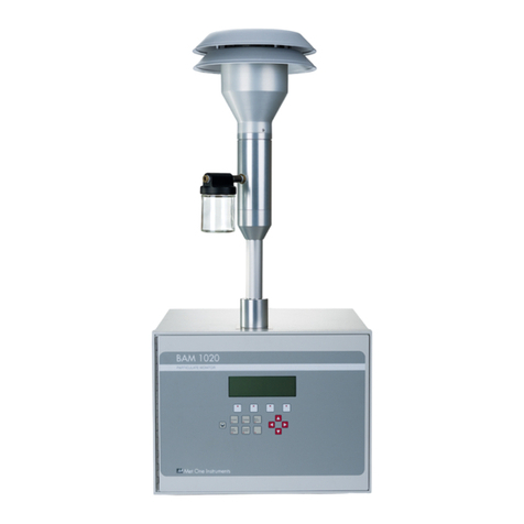
Met One Instruments BAM-1020 User manual

Met One Instruments
Met One Instruments C-12 User manual

Met One Instruments
Met One Instruments AEROCET-380 User manual

Met One Instruments
Met One Instruments E-Sampler User manual

Met One Instruments
Met One Instruments BAM-1020 Installation and operating instructions

Met One Instruments
Met One Instruments BAM 1022 Installation manual