META 13 RS User manual
Short cuts for parts:
SPL - Left side section
SSL - left part for side wall
SPM - Middle section
SPR - Right side section
SSR - right part for side wall
TW - Partition
SWF - End wall with leg
SCHW - Privacy screen
TUL - Left door
TUR - Right door
13 RS
INSTALLATION INSTRUCTION
The following parts are required:
• Electric drill with
5 mm and 8 mm SDS
• Various HSS-drills
3,5 mm, 4,2 mm, 6,5 mm
• Cordless screwdriver with bits TX
15, 20, 25, 30 mm PH2 cross
• Various allen keys
• Water level at least 1 m or laser
• Small wooden wedges
• Various Philips-HP screwdrivers
• Several wooden blocks height 15 cm
• Several glass blocks 5 mm
• Hammer, rubber hammer
• Pop rivet gun
• Standard tools
• At least 2 scissor jacks
• Chop and fermentation saw with
blade for aluminum
• Hand-held circular saw if required
with blade for plastic and
non-ferrous metals

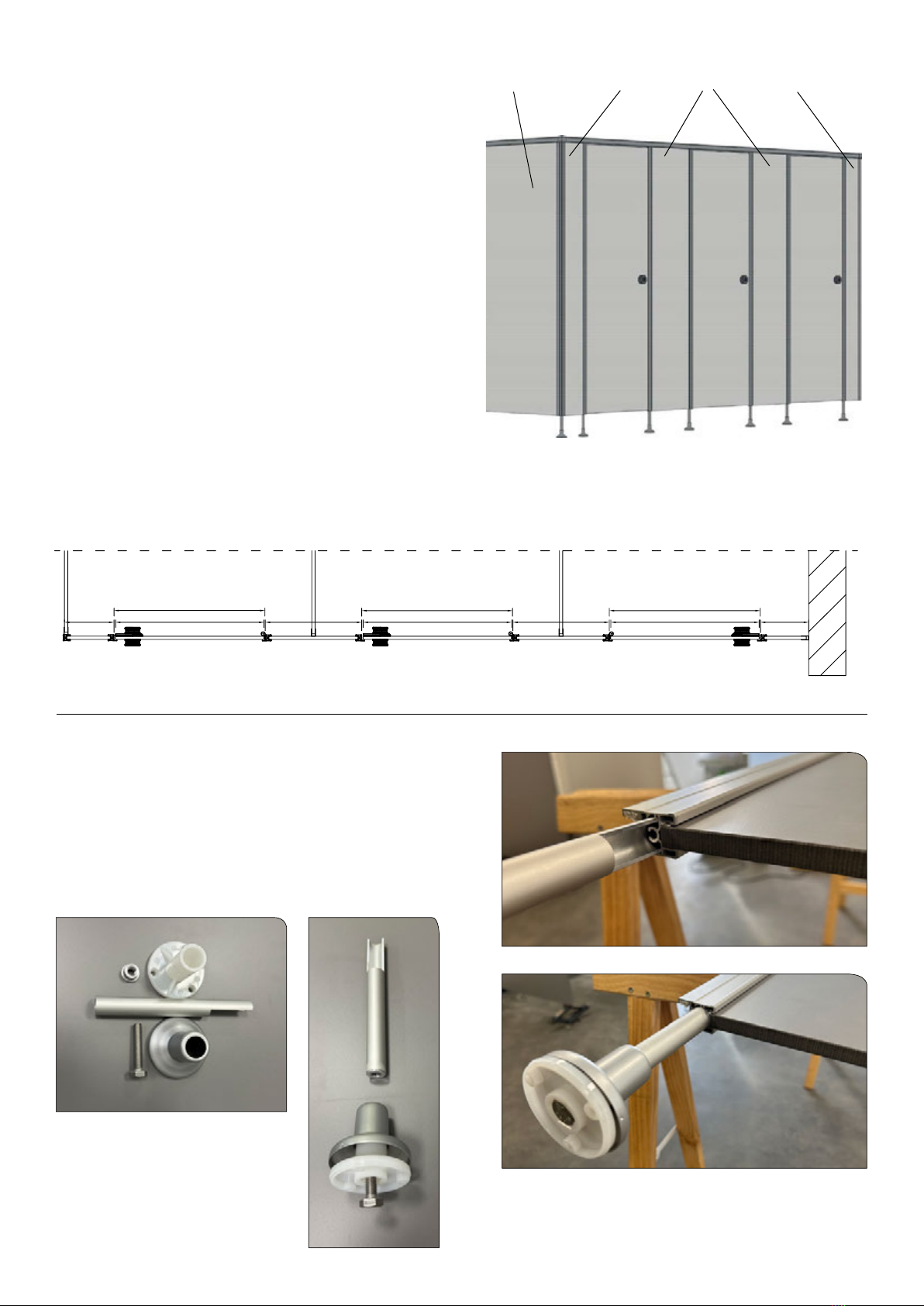
Marking of the wall connections (U proles)
The cabin axis dimensions (dimension 1) can be taken
from your drawing if neccessary. If no dimensions are
specied, the width of the system is divided into equal parts.
These axial dimensions are marked by a vertical line.
The U-prole is placed on a wooden block, which has the
height of the ground clearance.
Now mark the drill holes. (see photo)
For the axial dimension of the wall connection “a”,
27 mm must be added to the partition depth.
Draw a vertical line with a spirit level and mark the holes.
TW and SW are different.
The dimension of the TW is decisive.
Draw a vertical line with the water level and mark the holes as before.
If the oor is uneven or has a slope,
the standard foot clearance at the lowest point must be 150 mm.
Fastening of U-proles
Drill the 8 mm holes and insert 8 x 51 mm wall plugs.
Fasten the U proles with washers and 5 x 50 mm
chipboard screws.
Leave the wooden blocks in place.
Inserting partitions and side walls
Place the walls in the U-proles (please do not screw them
together yet).
A scissor jack is required for the front part of the partition wall.
Align the walls horizontally.
SSL
Example Dimension 1, 2, 3 = axial dimension
TWSW TW
Maß 1
z.b 913mm
SSL SPM SPM SPR
TU TUR
Maß 2
z.b 1437mm
Maß 1
z.b 913mm
Maß 1
z.b 913mm
TUR a
Dimension 1
e.g. 913 mm
Dimension 1
e.g. 913 mm
Dimension 3
e.g. 906,5 mm
Dimension 2
e.g. 1437 mm
1
Marking doors, middle,
side and corner parts
First of all, the dimensions of the front parts
have to be marked on the oor.
Please note the following:
End part
For end parts, the clearance in the drawing
must be added to the width of the end wall connection.
(Example: end section 100 mm, mark 110 mm on
the oor.)
Doors
For doors, add 10 mm to their width.
(Example: Door 600 mm, mark out 610 mm on the oor.)
Middle section
For middle sections, the exact width must be marked.
Corner section
For corner sections the width dimension (see example)
minus 15 mm is marked. This corresponds to the axial
dimension of the end wall. Now the front axle dimensions
are marked.
(Important for the distribution of the middle sections)
side wall
end part left
(corner section) middle parts
end part right
(wall connection)
600
610
200 390 600
610
390 600
610
195
z.B z.B z.B z.Bz.B z.B z.B
For checking:
If the axial dimensions of the front are parallel to the axial
dimensions of the U-proles on the rear wall, the elevation
is OK.
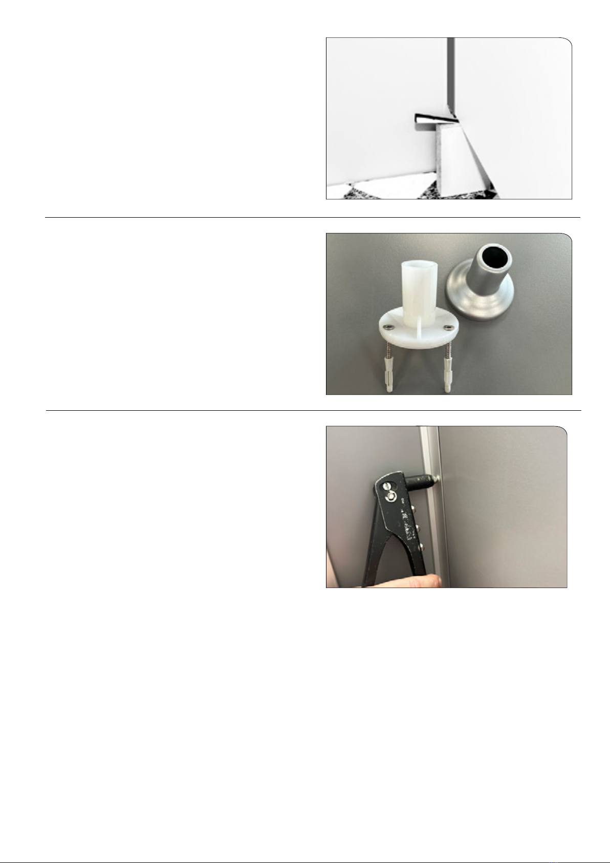
Installing the support feet and rosettes
Fit the support sleeve into the foot tube. Put on the rosette and
the base part and screw in the M10 x 50 screw from below.
Now hammer the foot with the recess into the prole.
2

Setting up the doors, middle-, end-
and corner parts
Place the side part on the marking and insert it into the
U-prole. (please do not screw yet)
For systems with a side wall
screw the U-prole with the recess onto the corner piece using
4,8 x 25 mm screws.
Place the U-prole U-13G (according to the dimensions in the
drawing) ush with the bottom and in the center of the middle
section, mark the drill holes, and fasten the U-prole with
4,8 x 11 mm screws (pre-drill 4,2 mm).
It is imperative that the exact drilling depth of 11 mm is
observed.
Slide the nished middle section onto the partition and fasten it
with 4 x 12 rivets.
Hang the doors, observing the exact door clearance of 5 mm on
the lock side.
The hinges are fastened to the doors with 6 stainless steel
screws 4,2 x 25 mm.
Lubricant should be applied to the screw tips beforehand.
3

upper door clearance lower door clearance
using 5 mm glass blocks
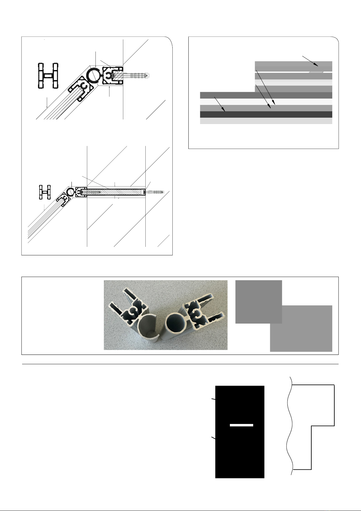
Corner connector
Mounting the cover proles
To determine the exact length of the cover proles (AD13RFK),
place the corner connector on the corners of the front and side
walls. Mark the cover proles and cut to length accordingly.
(Only if SW)
To attach the cover prole (AD13RFK), the holes in the prole
must be drilled in the area of the front so that they t into the
holes in the side, corner and SW proles. To do this, mark the
center of the screw channel on the longitudinal proles, place
the cover prole and transfer the marking.
4

5
Now drill the holes in the center of the front and side
cover proles in the area of the markings using a
6,5 mm diameter drill bit.
In the area of the wall connections, push the cover cap onto the cover prole and position the
proles on the system using the corner connector.
Then fasten the front cover prole from above with
6 x 80 mm screws
Use 4,8 x 28 pan-head screws to fasten
the cover prole above the side wall.
Finally, screw the cover caps with
4,8 x 16 screws from above.
6
Alignment of the system
Check that the door is properly aligned with the prole
and the distance to the upper prole. By raising or
lowering the partition and side walls, the door stop
can be changed.
If necessary, a correction can also be made using the
adjustable support feet.
Screwing and riveting the assembled system
The foot rosettes are usually glued. If screwing to the oor is
desired, push the cover cap (a) upwards and drill diagonally into
the oor through 2 holes of the base plate (b) using a 5 mm drill
bit.
Then insert dowels 5 x 31 mm and fasten with stainless steel
screws 4,8 x 32 mm.Press cover cap (a) onto base plate (b).
a
b
The wall proles must have the same height as the partitions.
The U-proles must butt against each other in the area of the
cover tubes. This may have to be corrected with a block and
hammer. Now rivet the walls and side mirrors with 4 x 12 rivets.
4 per side per prole.
7
Inclined wall connection Angling
If there is facing masonry in the area of the wall connections,
a recess is required. In this case, the procedure remains as
described in “Marking the wall connections”,
but in this case U-proles and at material must be cut.
Recess
Example: system with clearance
U-prole
Flat material
U-prole
A
B
13RF-Eckkabine neu ab 2023 mit schrägem Wandanschluss und Abwinklung
DETAIL A
MAßSTAB 1 : 2
SSR
ABW13RF-B
ABW13RF-A
SW
DETAIL B
MAßSTAB 1 : 2
Füllstück
ABW13RF-B
ABW13RF-A
SW
Wand
AD13RFK läuft über schräge hinweg
A A
B B
C C
D D
E E
F F
G G
H H
12
12
11
11
10
10
9
9
8
8
7
7
6
6
5
5
4
4
3
3
2
2
1
1
13RF-neu ab 2023-Eckkabine mit schrägem
Wandanschluss und Abwinklung
D.
Becker
GEWICHT:
A2
BLATT 1 VON 1
MASSSTAB:1:50
ZEICHNUNGSNR.
BENENNUNG:
ÄNDERUNG
ZEICHNUNG NICHT SKALIEREN
WERKSTOFF:
DATUM
SIGNATUR
NAME
ENTGRATEN
UND SCHARFE
KANTEN
BRECHEN
OBERFLÄCHENGÜTE:
WENN NICHT ANDERS DEFINIERT:
BEMASSUNGEN SIND IN MILLIMETER
OBERFLÄCHENBESCHAFFENHEIT:
TOLERANZEN:
LINEAR:
WINKEL:
QUALITÄT
PRODUKTION
GENEHMIGT
GEPRÜFT
GEZEICHNET
A = open
angling prole
B = closed
angling prole
Angle up to 90 to 162
degrees possible.
A B
Schräger Wandanschluß !
ABW13RF-A + ABW13RF-B
AD13RFK
AD13RFK
Füllstück
Schräger Wandanschluß mit Aussparung!
Hier wird eine Blende eingesetzt!
AD13RFK
Beidseitig Flachmaterial
UP13G
ABW13RF-A + ABW13RF-B
AD13RFK
Filler
Inclined wall connection with recess.
An orice plate is inserted here!
Flat material on both sides
8
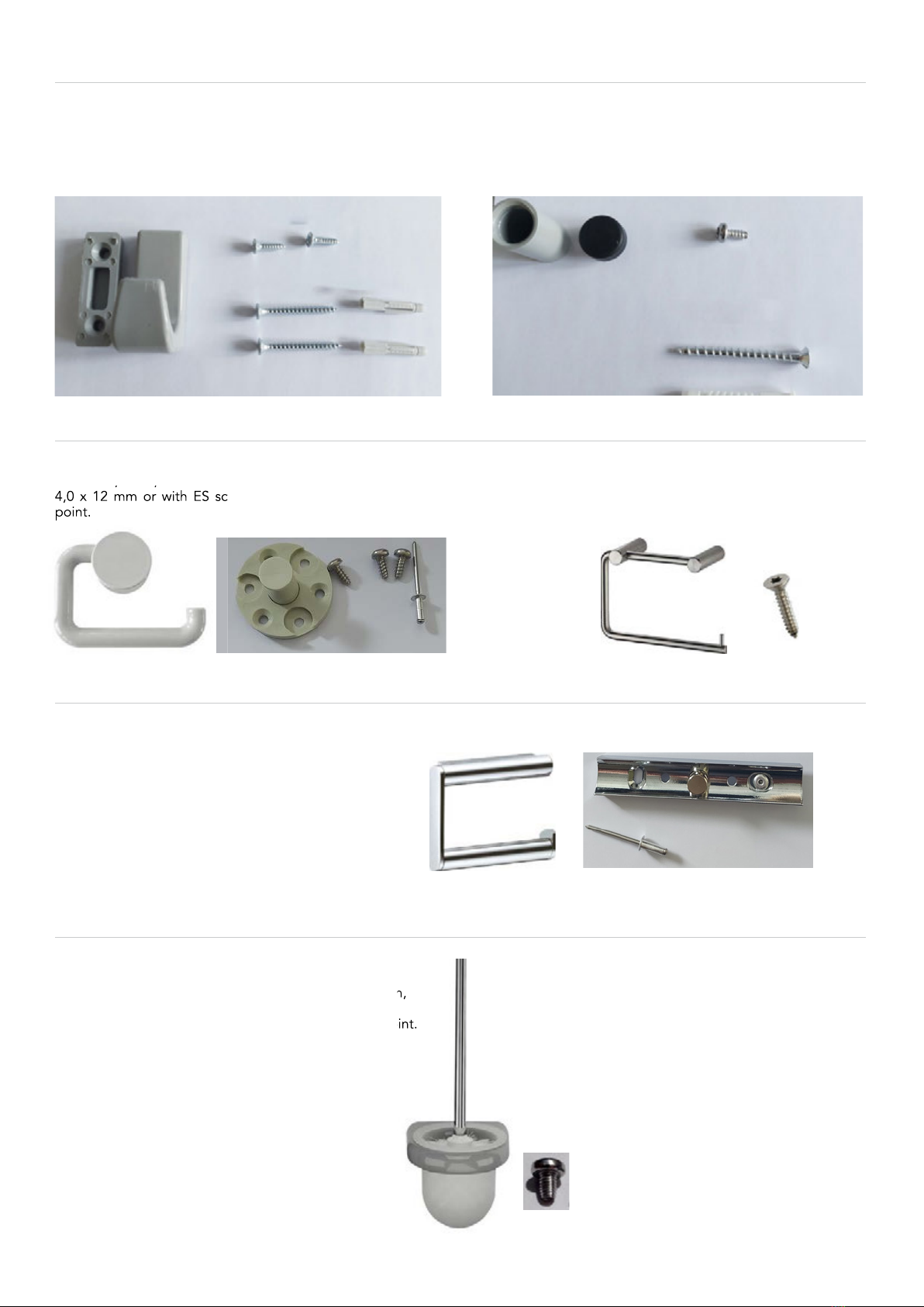
Mounting hook nylon
The hooks are marked and then fastened with 5 mm dowels
and screws 4 x 40. Use screws 3,9 x 13 when fastening to door
or TW. Pre-drill 3,5 mm with stop, max. 11 mm deep.
Then push on the rosette.
Mounting buffer nylon
Mark the buffers at the height of the door handles. Fasten
the bottom parts using an 8 mm dowel and screws 5 x 50
with washer. When fastening to the TW, use screws
4,8 x 11. For this purpose, predrill 4,2 mm with stop,
max. 11 mm deep. Then press on the buffer.
Mounting toilet roll holder
ECO nylon
Pre-drill 4,2 mm, max 11 mm deep. Fastening with rivets
4,0 x 12 mm or with ES screw 4,8 x 11 mm TX25 without
point.
KEUCO
Pre-drill 4,2 mm, max 11 mm deep.
The fastening is done with aluminum blind rivets
4,0 x 12 mm.
Nylon
When fastening to partition or side wall pre-drill 4,2 mm,
max 11 mm deep.
Fastening with ES screws 4,8 x 11 mm TX25 without point.
For masonry wall use screws and dowels.
(are included with the brush).
Pre-drill 4,2 mm, max 11 mm deep. Fastening with rivets
4,0 x 12 mm or with ES screw 4,8 x 11 mm TX25 without
point.
Stainless steel
Pre-drill 4,2 mm, max 11 mm deep.
Fixing with ES screw 4,8 x 22 mm TX25.
When fastening to partition or side wall pre-drill 4,2 mm,
Fastening with ES screws 4,8 x 11 mm TX25 without point.
Mounting toilet brush unit
short screws for 13 mm sheets
long screws for masonry
short screws for 13 mm sheets
long screws for masonry with dowel
dowel 8 x 48 Torx
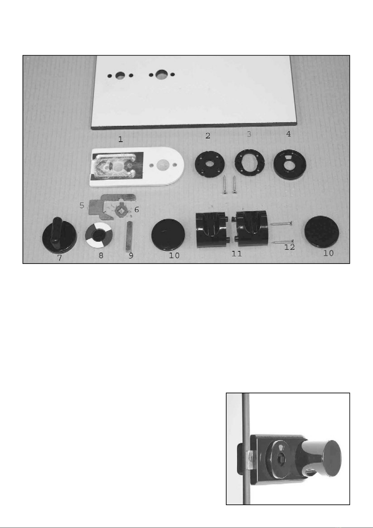
Installation Lock RS1
Always place the lock case on the side after which the door is opened.
First the 2 coiled spring pins (3 x 10 mm, without illustration) must be inserted into the housing (1) with pliers.
(squeeze if necessary)
The base plates of the red/white locking device (2, 3) and the 2 screws 3,5 x 35 (12) must be ready to hand
before attaching the lock case.
Insert the cam (6) with the long tab upwards into the lock case (1) and add the slider (5). Insert this sub-unit with
the dowel pins through the door bore, possibly press together with pliers.
Insert the base plate (3) on the side on which the red/white disc appears later.
Place the base plate (2) on the other side of the door and screw both parts together.
The square (9) is now inserted into the locking knob (7).
This unit is now inserted with the square through the cam
in the lock case and pressed rmly.
Put the red/white indicator (8) with the external emergency release
to the outside on the square pin (9) and then x it by pressing on
the rosette.
The button parts (11) are fastened with the screws (12).
Finally move the cover caps (10) onto the buttons and
check the lock for function.
the following tools are required: Phillips-HP screwdriver
Torx driver 15
small hammer
fully assembled lock
for doors that open
outwards
Installation lock RS2, RS3 the following tools are required: Phillips-HP screwdriver
Torx key 15
small hammer
Allen key 2,5 mm
(1)
(2)
(3)
(5)
(8)
(7)
(6)
(4)
First, the 2 dowel pins (3 x 10 mm, without
illustration) must be inserted into the housing (1).
(possibly press together with pliers)
The housing with inserted slider (2) and cams (3) is
now attached with the 3.9 x 22 screw (4)
(Torx 15) on the side after which the door is opened.
Insert the square pin (6) into the red/white-knob (7)
For doors that open inwards, insert this unit from the
outside through the door and the cam.
Screw it together with 2 Torx-screws 3,9 x 32 (5).
Observe the position of the red/white-indicator!
From the opposite side, slide the knob (8) onto
the square.
With a 2,5 mm allen key, the rotary knob,
is screwed with the red-white-side under
pressure on the square.
Attention! Don`t treat stainless-steel with
acidic cleaner!

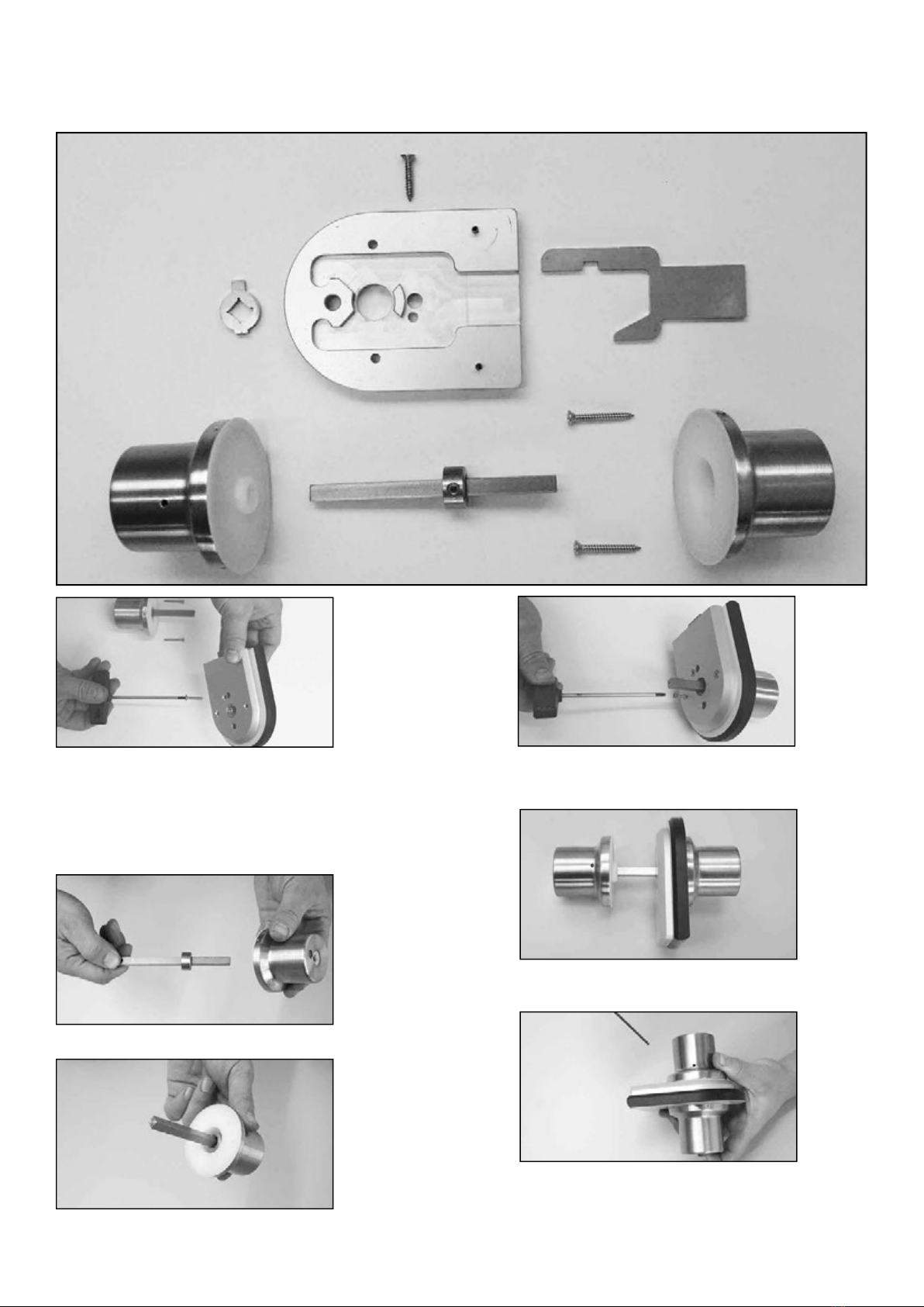
Installation lock RS4 the following tools are required: Torx key 15 und 20
Allen key 2,5 mm
Remove foil from lock case (Attention: loose parts)
Put the lock case with 3 mm dowel pins on the door
and fasten it with screw 3,8 x 21. The slider must be in
the lock case. It has to be preparated for DIN R, as shown.
For DIN L the slide and the cam must be ipped.
Insert the square with the red/white indicator
into the display unit. „White“ must be displayed in the
viewing window.
Now insert the knob through the lock case.
The attened side of the square must face down.
The basic part is now attached from the other
side and is screwed with the 2 screws
M5 x 45 (Torx 20), through the lock case, to the
red/white indicator knob.
Put on the turning part. The movement can be
adjusted by pressing the knob and holding the
square on the other side.
Finally fasten the knob with a 2,5 mm Allen key.
Ground part (POM)
(3033)
Indicator part
(3031)
Turned part
(2925) Square with red/white
(3066) und (3142)
Fixing screws
M5 x 45 ES SK DIN 965 (2920)
Lock case xing screw
3,9 x 22 ES SK Tx 15
DIN 7982 (3146)
Lock case
(2148)
Cam
(2103)
Slide
(2127)
12
Keep the door closed.
Remove the cover cap and unloose the setscrew
with a 2,5 mm Allen key.
Tense the springe hinge with a 6 mm Allen key.
If the spring pin is tightened in the door closing
direction, the door closes automatically.
If the door schould open automatically
spring bar must be tightened in the other direction.
Prestress a maximum of 2 grid points.
No more than 120°.
(Risk of spring overload)
Now tighten the setscrew again and t the cover cap.
How to tense spring hinges
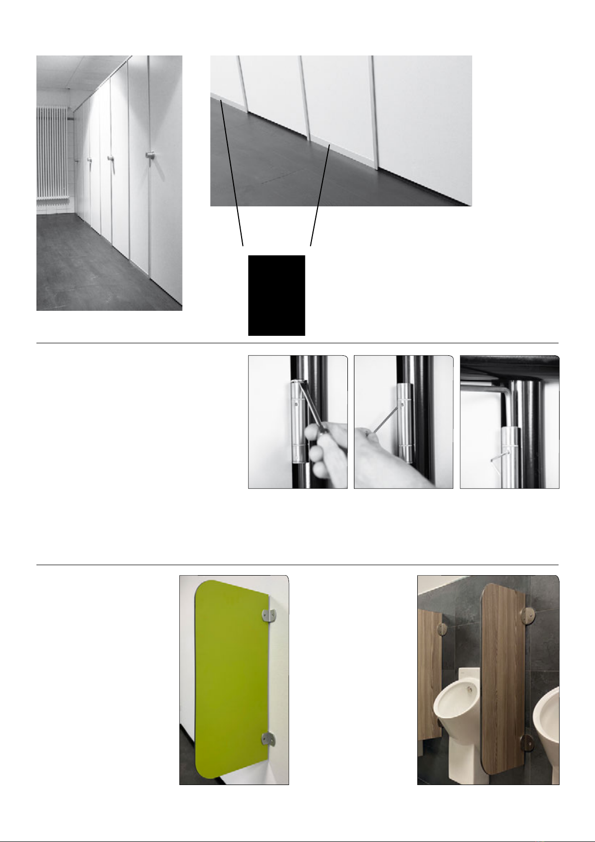
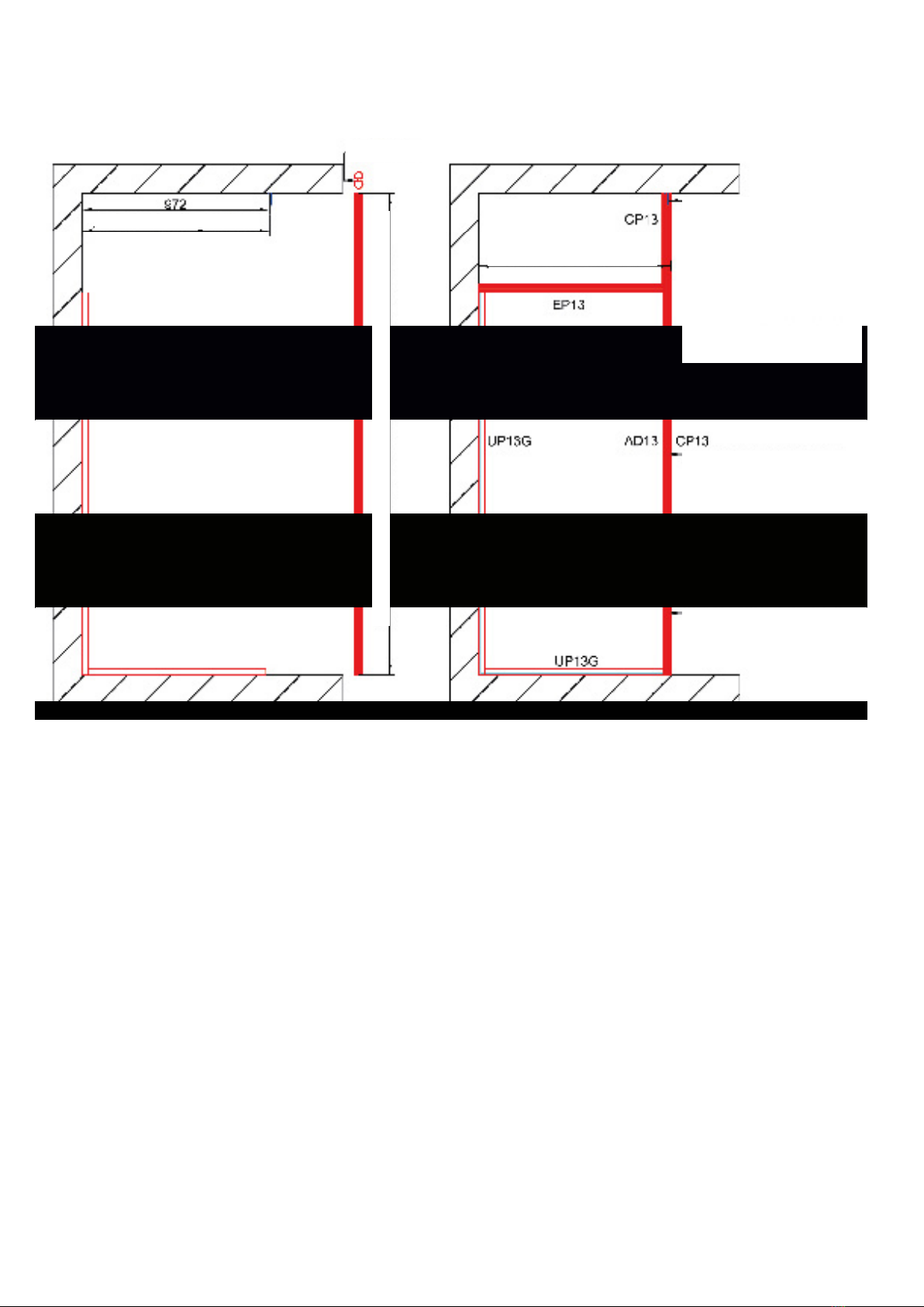
Urinal screens
Aluminium support angle
Type 13 RS without clearance
UP13G
For the oor connection, the UP13G proles
must be cut to the width of the front
elements on site.
They are then screwed to the oor.
Stainless steel
support angle
The mounting materials are included in the scope of delivery in each case.

Example: Floor- and ceiling support with clearance!
Measurements Installed system
Installation procedure
Draw a vertical line with the spirit level at the position where the wall is to be mounted
and mark the holes for the UP13G.
Also mark the two angles at oor and ceiling. Same axial dimension as the UP13G.
Formula: outer dimension -28 mm.
Now drill 8 mm holes and insert dowels 8 x 51 mm.
Fit the UP13G to the specied size using washers and 5 x 50 mm Spax screws.
Mount the two brackets with 5 x 50 mm Spax screws.
Cut the AD13 to length on both heads.
Formula: clear height -2 mm.
The reccesses of AD 13 must face the xed wall.
Place the 13 mm sheet in the U-prole. Place the front part on a wooden block and in the scale.
Now the wall is xed with 4 rivets. Pre-drill 4,0 mm for this.
The AD13 is now screwed to the top and bottom angles with 4,8 x 16 mm screws. Furthermore, the AD13 must be
connected to the 13 mm sheet. Pre-drill 4,2 mm into the plate and screw together with 4,8 x 32 mm screws.
Attention! Drill straight into the plate to avoid tearing!
Now the EP13 is cut to size and glued with silicone (on site). Formula: Outer dimension -45 mm.
Finally, the CP13 are cut to length and inserted.
Recess
Axis measure for angle
Cut the stiffening prole on both sides equally to the length
Fixing AD13 to angle
with 4,8 x 16 mm screws
Fixing AD13 to sheet
with 4,8 x 32 mm screws
Fixing AD13 to sheet
with 4,8 x 32 mm screws
Fixing AD13 to sheet
with 4,8 x 32 mm screws
Fixing AD13 to angle
with 4,8 x 16 mm screws
External dimension 1000 mm
Cut the lower UP13G to length. Formula: Outer dimension -75 mm.
Draw a vertical line with the spirit level at the position where the wall is to be mounted
and mark the holes for the UP13G.
Also mark the angle at the ceiling. Same axis measure as at the UP13G.
Formula: external dimension -28 mm.
Now drill 8 mm holes and insert dowels 8 x 51 mm.
Fit the UP13G to the specied size using washers and 5 x 50 mm Spax screws.
Mount the two brackets with 5 x 50 mm Spax screws.
Cut the AD13 to length on both heads.
Formula: clear height -2 mm.
The reccesses of AD 13 must face the xed wall.
Place the 13 mm sheet in the U-prole. Place the front part on a wooden block and in the scale.
Now the wall is xed with 4 rivets. Pre-drill 4,0 mm for this.
The AD13 is now screwed to the top and bottom angles with 4,8 x 16 mm screws. Furthermore, the AD13 must be
connected to the 13 mm sheet. Pre-drill 4,2 mm into the plate and screw together with 4,8 x 32 mm screws.
Attention! Drill straight into the plate to avoid tearing!
Now the EP13 is cut to size and glued with silicone (on site). Formula: Outer dimension -45 mm.
Finally, the CP13 are cut to length and inserted.
Example: Floor- and ceiling support without clearance!
Measurements Installed system
Recess
Axis measure for angle
Cut the stiffening prole on both sides equally to the length
Fixing AD13 to angle
with 4,8 x 16 mm screws
Fixing AD13 to sheet
with 4,8 x 32 mm screws
Fixing AD13 to sheet
with 4,8 x 32 mm screws
Fixing AD13 to sheet
with 4,8 x 32 mm screws
External dimension 1000 mm

meta Trennwandanlagen • Metastraße 2 • D-56579 Rengsdorf • Tel. +49 26 34 / 66-0 • Fax +49 26 34 / 66 450 • E-mail: [email protected] • Internet: www.meta.de 10/23
Table of contents
Other META Indoor Furnishing manuals


Popular Indoor Furnishing manuals by other brands


SleepSafe Beds
SleepSafe Beds SleepSafe Product Assembly Guide

Safavieh Furniture
Safavieh Furniture Bennet MCR4737 quick start guide

ggm moebel INTERNATIONAL
ggm moebel INTERNATIONAL Coco Manual instruction

Rauch
Rauch M2659 Assembly instructions

RH Baby&child
RH Baby&child WOOD SHADOW-BOX Assembly instructions

Songmics
Songmics LCD871 instructions


