2
The liner should terminate with the lowest discharge opening no closer
to the roof than the minimum height shown in the table below. These
minimum heights may be used provided the vent is not less than 8 ft.
(2.4 m) from any vertical wall.
Roof Pitch Minimum Height
Flat to 6/12 1.0 foot (305mm)
6/12 to 7/12 1.25 feet (380mm)
Over 7/12 to 8/12 1.5 feet (451mm)
Over 8/12 to 9/12 2.0 feet (610mm)
Over 9/12 to 10/12 2.5 feet (762mm)
Over 10/12 to 11/12 3.25 feet (991mm)
Over 11/12 to 12/12 4.0 feet (1218mm)
Over 12/12 to 14/12 5.0 feet (1524mm)
Over 14/12 to 16/12 6.0 feet (1829mm)
Over 16/12 to 18/12 7.0 feet (2134mm)
Over 18/12 to 20/12 7.5 feet (2286mm)
Over 20/12 to 21/12 8.0 feet (2438mm)
GENERAL:
MLK and MLKE gas vent lining systems are listed by UL & ULC for
installation at zero clearance to the inside masonry surface and with
zero clearance from the outside surface of the masonry chimney and
surrounding combustible material.
Do not place insulation or other materials in required clearance spaces
surrounding the liner unless otherwise specied.
Use only parts referenced in the these instructions when installing a MLK
or MLKE liner system. Never substitute liner material.
Rain caps and ashing must be used to prevent moisture from entering
the liner and entering the space between liner and chimney. Bird screens
on rain caps may be necessary and/or required in some areas but could
be susceptible to blockage through freezing moisture. Consult authority
having jurisdiction before using bird screen.
Metal-Fab MLK liners may be extended from the outlet (top), to the cap
using Type-B gas vent. MLK and MLKE liners may be extended from
the inlet (bottom) to the appliance using exible MLCK connectors (See
FIG. 6 & 8).
Metal-Fab MLK and MLKE liners may be connected continuously from
the appliance to the termination cap, provided that the liner is always
in an unenclosed space or is within a masonry chimney, factory built
chimney, or Type-B gas vent.
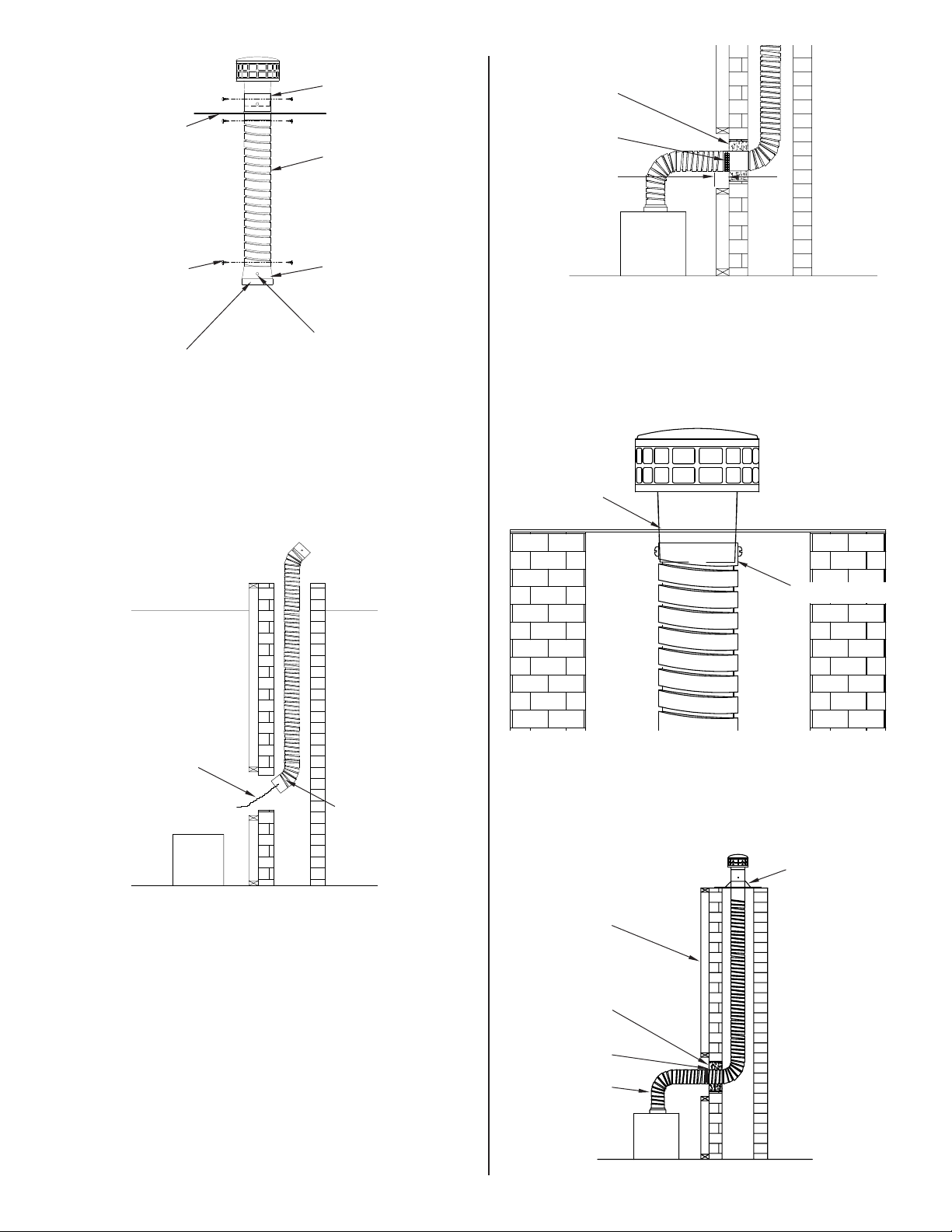
CONNECTOR
(MLK ONLY)
STORM COLLAR
(MLK ONLY)
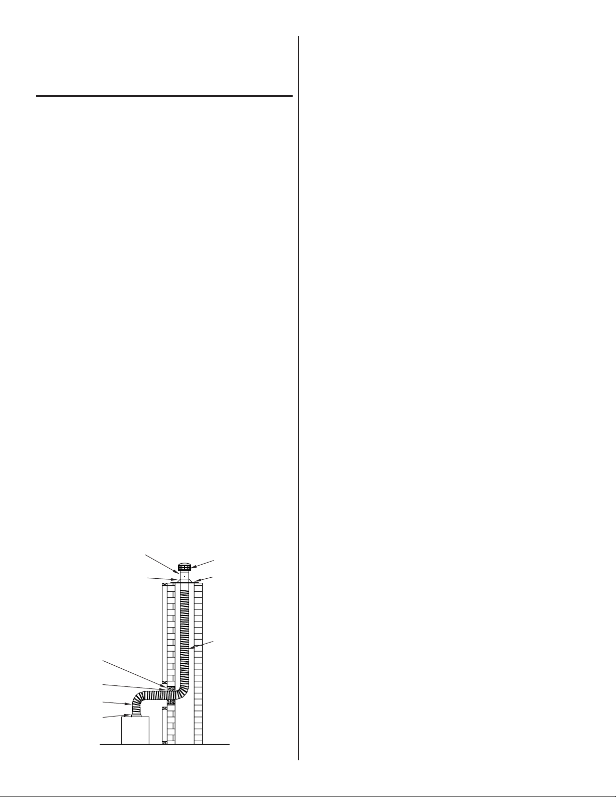
CAP
FLASHING
FLEXIBLE LINER
NON-COMBUSTIBLE
FILLER MATERIAL
MORTAR GUARD
FLEXIBLE LINER
APPLIANCE OUTLET
(CONNECTOR
COLLAR NOT
PROVIDED)
APPLIANCE
FIG. 1
These liner systems are NOT listed as Type-B gas vent and are
not intended to pass through any wall, ceiling, attic, crawl space or
other combustible area. A liner that is used as a connector in open
and unenclosed space must be installed with minimum clearance to
combustibles, in accordance with NFPA 211. The appliance to which the
exible liner is connected shall be listed gas-red appliance equipped
with a draft hood or other appliance listed for use with Type-B Vent.
To size the liner system, follow the Category 1 venting table now
contained in the National Fuel Gas Code NFPA 54/ANSI Z223.1 in the
USA or CAN CSA-B149.1 in Canada. Be certain to follow the capacity
reduction directions for the corrugated metallic chimney liner systems.
While installing exible liner, consideration should be given to the
following: 1) make no unnecessary bends 2) make no bends greater
than 90° 3) make bends as smooth as possible, with no dips or sags and
4) install with at least a 1/4” per foot rise.
Before installing liner authorities having jurisdiction (such as Gas
Inspection Authority, Municipal Building Department, Fire Department,
Fire Prevention Bureau, etc.) should be consulted to determine the need
to obtain a permit.
The installer must post the completed date of installation notice at the
point where the connection is made to the appliance. This notice shall
include date of installation, the manufacturer’s name, the model number
and class of lining system, and a reminder to homeowners to check the
rain cap for icing during low ambient temperatures.
INSTALLATION:
1. MLK/MLKE: Determine the length of the liner needed by dropping a
pre-measured length of rope or other measuring device down the
chimney. If the liner is to mate directly to an appliance, measure all
the way to the appliance. Otherwise, measure to a point that is just
outside of the chimney that is being re-lined.
2. MLK/MLKE: If installing the liner into a masonry chimney, determine
the location of the point where the ex system will penetrate the
masonry sidewall. This opening must be located above the appliance
outlet. It is recommended that you install an inspection/cleanout
door on the opposite side of the chimney, if conditions permit.
3. MLK/MLKE: To congure the liner to it’s proper length, remove the
liner from the carton. One person (wearing gloves) is to securely
grasp one end of the liner while the second person (also wearing
gloves) pulls and stretches the liner from the other end. Both persons
should be on level ground when stretching the liner. Pull and stretch
to the required length, being careful not to over-stretch the liner.
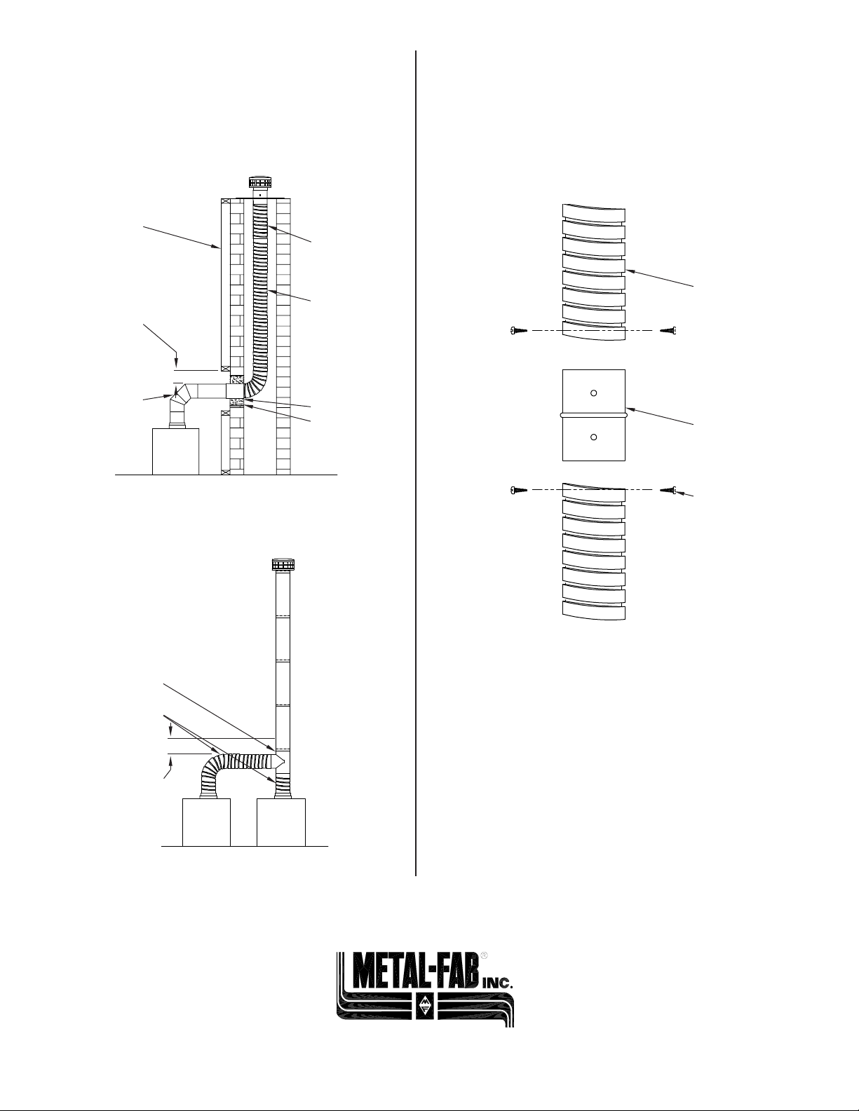
NOTE: For shipping purposes, the exible liner has been
compressed to approximately 1/3 it’s usual length. A
25-foot (7.62 m) length will be approximately 8 feet
(2.44 m) in the carton. For taller chimneys two lengths of
liner can be joined together (See Flex Extension on
Page 4).
4. MLKE Only: While still on level ground, press a termination into the
ashing until the tapered termination collar makes contact with
ashing. Attach one end of the exible liner to the portion of the
termination protruding below the ashing (use 3 ea. screws
provided). Attach sleeve/connector to the inlet (bottom) end
of the exible liner (use 3 ea. screws provided). Temporarily
attach a bolt through the holes that are provided in the sleeve
connector to serve as a pull bar. You are now ready to lower the ex
into the chimney from the top down (See FIG. 2).
5. MLK Only: This liner has a B-Vent style connector
pre-attached to the outlet (top) end of the ex and a stainless
steel slip connector pre-attached to the inlet (bottom) end.
You are now ready to lower the ex into the chimney from
the top down.