Metal Fab Temp/Guard User manual
2100°TEMP/GUARD CHIMNEY
SIZES 6” - 7” - 8” - 10” - 12”
TEMP/GUARD®
INSTALLATION AND MAINTENANCE
INSTRUCTIONS
This symbol on the nameplate
means this product is listed by
Underwriters Laboratories Inc.
Listing No. MH 8251
Tested to 103 HT
A MAJOR CAUSE OF CHIMNEY RELATED FIRES IS FAILURE TO MAINTAIN
REQUIRED CLEARANCES (AIR SPACES) TO COMBUSTIBLE MATERIAL.*
MINIMUM CLEARANCE FOR 6” - 8” TEMP/GUARD IS ONE AND A HALF
(1-1/2) INCHES. MINIMUM CLEARANCE FOR 10” - 12” TEMP/GUARD IS
TWO (2) INCHES. IT IS OF UTMOST IMPORTANCE THAT THIS CHIMNEY
IS INSTALLED ONLY IN ACCORDANCE WITH THESE INSTRUCTIONS.
WARNING: FOR SIZES 6”, 7” & 8” CHIMNEY, MINIMUM CLEARANCE TO COMBUSTIBLE
MATERIAL MUST BE TWO (2) INCHES UNLESS ALL CHIMNEY COMPONENTS ARE
LABELED TG MAX.
*Combustible material is dened as material made of, or surfaced with, wood, compressed paper, plant bers,
plastic, or other material that will ignite and burn, whether ame proofed or not, or whether plastered or unplastered.
The Metal-Fab Temp/Guard Chimney is intended for use on any residential and building heating appliance burning gas,
liquid or solid fuels such as replace stoves, furnaces, ranges, room heaters, or as dened in columns I and II, Table
2-2.1, NFPA 211. Contact Local Building or Fire Ofcials about restrictions and Installation Inspection in your area.
WARNING: Metal-Fab Temp/Guard Chimney is not designed for use on products that operate at continuous
temperatures in excess of 1,000°F.
WARNING: If decorative shrouds are being used with Temp/Guard Chimney, Reference the Temp/Guard Addendum L2372.
IMPORTANT: FOR OIL OR COAL BURNING APPLIANCES, OUTSIDE THE ENVELOPE OF THE BUILDING, USE ONLY PIPE WITH
STAINLESS STEEL CASING, ALSO USE FLASHING OR STORM COLLARS CONSTRUCTED OF STAINLESS STEEL OR ALUMINUM.
OPERATIONAL PRECAUTIONS
• Maintain 1-1/2” minimum clearance to combustibles for 6”- 8” diameters and 2” minimum clearance to combustibles
for 10”-12” diameters (Refer to WARNING above). Use only U.L. Listed products and INSTALL ONLY IN
ACCORDANCE WITH MANUFACTURER’S INSTRUCTIONS.
• Formation of Creosote and Soot and the need for removal.
When wood is burned slowly, it produces tar and other organic vapors, which combine with expelled moisture to
create creosote. The creosote vapors condense in the relatively cool chimney ue of the slow burning re. As a
result, creosote residue accumulates on the ue lining. When ignited, this creosote makes an extremely hot re.
The chimney should be inspected at least once every two (2) months during the heating season to determine if
a creosote or soot buildup has occurred. If creosote or soot has accumulated, it should be removed to reduce
the risk of chimney re.
• Do not use replace for food grill. Grease from foods can collect in chimney causing replace to become a potential re
hazard.
• On airtight stoves, open dampers and let equipment burn hot for 15 to 20 minutes. This should be done every time fuel is added.
This lessens the chance of creosote buildup.
• Some chemical chimney cleaners can be harmful to the chimney. These cause accelerated oxidation or corrosion.
If chemical cleaners are used, they must be non-corrosive in nature. If brush is used, it must be of proper size with
plastic bristles.
PAINT TOUCH-UP
• The at-black paint used on painted parts may be touched up,as required, with Stove Bright®Product No. 1990.

2
INSTALLATION THROUGH FLAT
CEILING(S)
1. From the appliance manufacturer’s instructions, determine
the correct ue diameter for the chimney, and proper
location of the chimney.
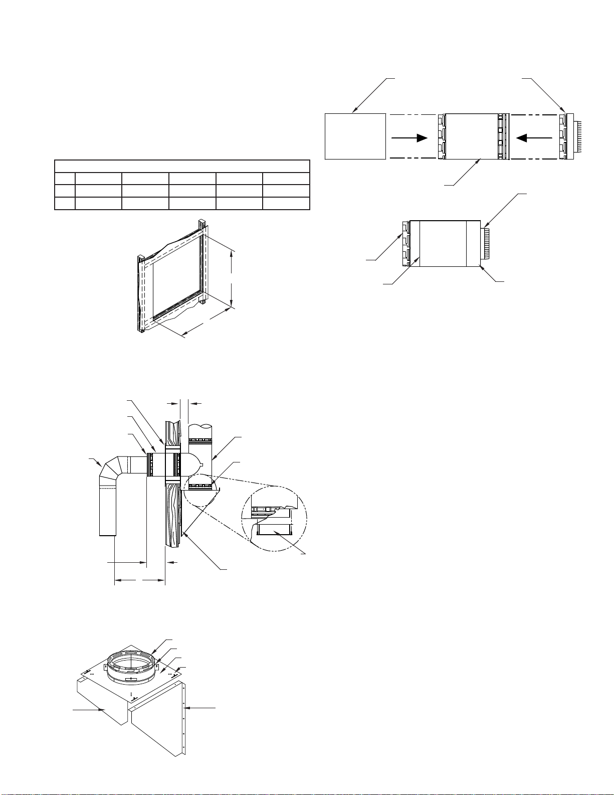
2. Using framing lumber equal to ceiling joist size, frame ceiling
opening as shown in FIG. 1 and TABLE 1.
TABLE 1
CHIMNEY FLUE DIAMETER
6” 7” 8” 10” 12”
A 12-7/16” 13-7/16” 14-7/16” 17” 19”
B 12-7/16” 13-7/16” 14-7/16” 17” 19”
NOTE: If possible, it is recommended that the chimney be
located in such a manner as to not cut the ceiling joist. For
the 8TG chimney, design and testing allows the clearance to
combustibles to be 1½ inches through the ceiling joist (using
the 8TGCSP) and through the roof joists. The chimney can be
centered between joists on 16 inch centers in these areas.
3. As shown in FIG. 2, insert the Ceiling Support (TGCSP)
from below until the anged edges are rmly against the
ceiling drywall. Secure into framing with eight (8) 8-penny
nails inserted through the sides of the ceiling support. If
the TGCSP was installed during construction and drywall
now covers the anged edges, install Metal-Fab’s ceiling
support trim kit (TGCST), as shown in FIG. 3.
4. Single wall or double wall connector pipe may now be
installed between the appliance and the ceiling support.
(See FIG 2.)
If the area above the ceiling is an attic, go to step 7.
5. Proceed to the next ceiling. If Metal-Fab Elbows are to
be used because the chimney is to be offset, refer to
“Installation of Elbows” section. Directly above the
Center of the ue in the ceiling support, mark the ceiling. A
plumb bob is normally used to nd the center. Cut an
opening in the ceiling using FIG. 1 and Table 1.
6. Install Temp Guard chimney sections starting at the TGCSP.
Secure the sections by pushing together and twisting until
stop-locked (See FIG. 3a). Additional chimney sections
may be added to maximum height of 60 feet. At
each additional ceiling, a restop (TGFSA) is required.
Insert the TGFSA into the joist area prepared in step 5.
Continue this process for each oor level until the area
above the attic.
NOTE: When the chimney extends between oors, which
can be occupied, the chimney must be enclosed to
prevent contact. As previously noted, 1-1/2” clearance
to combustibles for 6”- 8” diameters and 2” clearance to
combustibles for 10” to 12” diameters is to be maintained,
except within the joist area controlled by the TGCSP.
7. The rst chimney section through the joist area into attic is
to be approximately two (2) feet. If the pipe sections in the
attic are not enclosed, an insulation shield (TGIS) must be
installed. Lower insulation shield (TGIS) over TG pipe until
the ange is resting on the joist. Secure the TGIS in place
by nailing the ange to the joist. See FIG. 4. If the section
within the attic area is to be chase enclosed, the TGIS is
not required.
8. Continue the chimney to the roof. See “Flashing Installation”
and “Termination” sections.
L944 FIG03A
B
A
FIG. 1
Framing lumber of
equal size to the joist should be used.
L944 FIG02
PROPER CLEARANCE TO
COMBUSTIBLES WITHIN JOIST
AREA CONTROLLED BY TGCSP
CHIMNEY PIPE
(CAT. NO. TG)
CEILING DRYWALL
FLANGED EDGE
SINGLE OR
DOUBLE WALL
CONNECTOR PIPE
ATTACH TO
TGCSP WITH
SCREWS
CEILING
SUPPORT
(CAT. NO. TGCSP)
FIG. 2
L944 FIG03
CEILING
DRYWALL
FLANGE
COVERED
BY DRYWALL
CEILING
SUPPORT TRIM
(CAT. NO. TGCST)
FIG. 3
TWIST LOCK JOINT
FIG. 3a
L944 FIG04
FIG. 4
INSULATION SHIELD
(CAT. NO. TGIS)
NAIL
FIRESTOP
(CAT. NO. TGFSA)
3
INSTALLATION THROUGH SIDE WALL
1. Locate the area where the chimney section is to penetrate
the vertical wall. Cut and frame an opening so that
the ue is centered between the vertical wall studs on 6”,
7” and 8” systems. Note that 10”, and 12” systems may
require relocation of wall studs to maintain 2” clearance
to combustibles. Consult local authorities if structural
modications are required. Frame opening per FIG. 5 and
Table 2.
TABLE 2
CHIMNEY FLUE DIAMETER
6” 7” 8” 10” 12”
A 12-7/16” 13-7/16” 14-7/16” 17” 19”
B 13” 14” 15” 17” 19”
2. A wall restop (TGWFSP) must be installed in framed
opening from the outside. Push remaining half through
opening from inside until plate is ush. Use four (4) #10 x
2 ½” wood screws to attach to opening. (See FIG. 6).
3. Remove wall support adaptor from TGWS box and attach
adaptor to bottom of tee by inserting into bottom of tee and
rotating to lock.
4. Insert the side tap of the tee into the opening in the wall
restop.
5. Assemble right and left gusset to support plate using
hardware provided.
6. Attach wall support plate to wall support adaptor using 4
clamps provided. Do not tighten. (See FIG. 6a).
7. Align wall support with wall and secure to wall studs using
5/16” x 2” lag screws (not provided). DO NOT SECURE TO
SIDING. For masonry walls, use 5/16” x 2” masonry lag
bolts.
8. Install tee cap to bottom of wall support adaptor with a
minimum of two (2) #10 x ½” sheet metal screws.
9. Position tee and adapter on wall support to maintain
2” clearance to combustibles. TIGHTEN CLAMPS.
10. Slip a trim sleeve joint cover (TGTS) over the male end of
TG pipe that is to reach through the wall restop to the tee.
Attach single wall adapter (TGPSWA) to the female end of
TG pipe and slip TGTS ush to the end of TGPSWA. (See
FIG. 7a and 7b.)
11. Slide Metal-Fab chimney pipe into top of tee. Align male
and female ends. Push down on pipe sections and turn
clockwise to lock. Additional chimney sections are added
and locked to a MAXIMUM OF 60 FEET. As sections are
added, it will be necessary to secure them to the outside
wall with bands (TGWB) at eight-foot intervals and 2” from
combustibles. Wall bands (TGWB) are secured to the
chimney by placing band around the chimney and tightening
clamping bolt. The assembly is anchored to the wall studs
(not the siding) with 5/8” x 2” lag bolts. To complete the
chimney installation, see “Flashing Installation” and
“Termination” sections.
A
B
FIG. 5
L944 FIG06A
LEFT
GUSSET RIGHT GUSSET
(ATTACH GUSSETS TO
WALLSTUDS USING 5/16”
X 2” LONG LAG SCREWS)
WALL SUPPORTADAPTOR ASSEMBLY (1 EA.)
CLAMPS (4 EA.)
SUPPORT PLATE (1 EA.)
10-32 HEX NUTS & MACHINE SCREWS
SUPPLIED WITH TGWS (8 EA.)
TGTS TGSWA
TG PIPE TGSWA
ALIGN FLUSH WITH
EDGE OF TGSWA
TG PIPE
TGTS
FIG. 7b
FIG. 7a
AIR CLEARANCE 2”
TO COMBUSTIBLES
CHIMNEY TEE
(CAT. NO. TGT)
WALL SUPPORT
ADAPTOR
WALL SUPPORT
(CAT. NO. TGWS)
TEE CAP SUPPLIED
WITH TGT
WALL FIRESTOP
(CAT. NO. TGWFSP)
CHIMNEY PIPE
(CAT. NO. TG)
SINGLE WALL
ADAPTOR
(CAT. NO. TGSWA)
SINGLE OR
DOUBLE
WALL BLACK
STOVE PIPE
6 INCH MIN.
THRU WALLS L
L=18” FOR SINGLE WALL BLACK STOVE PIPE
L=6” FOR DOUBLE WALL BLACK STOVE PIPE
FIG. 6
FIG. 6a
4
HIGH PITCH OR
CHALET CEILING
ROOF SUPPORT
(CAT. NO. TGRS)
(4) NAILS PER SIDE
TEMP GUARD
ADAPTOR INCLUDED
FIG. 8
FIG. 9
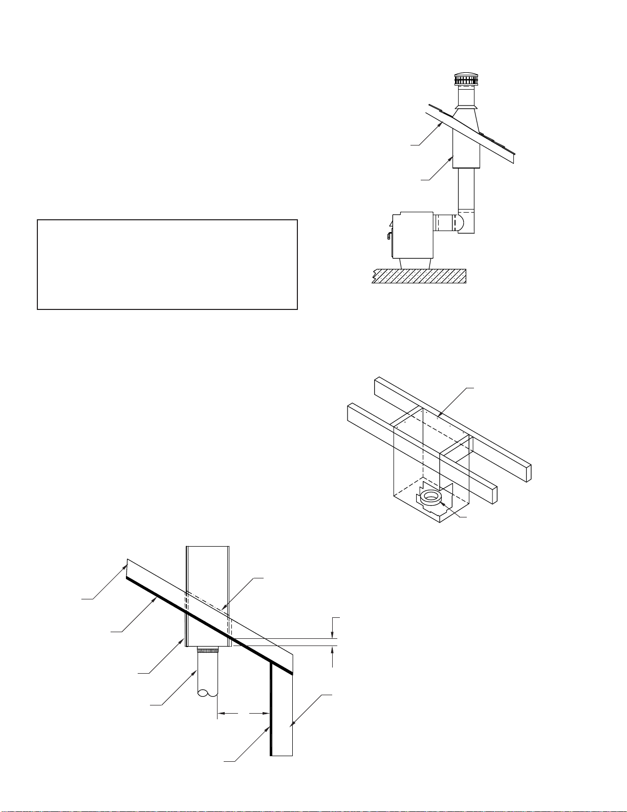
INSTALLATION THROUGH HIGH
PITCH OR CHALET CEILING USING
TGRS
1. From the appliance manufacturer’s instructions, determine
the correct ue diameter for the chimney and proper location
of the chimney.
2. Using framing lumber equal to ceiling joist size, frame
opening as shown in FIG. 9. Framing that is perpendicular
to the roof joists must also be vertically mounted so that
support can be installed vertically.
Opening dimensions will vary based on roof pitch (slope).
Framed openings should be approximately ¼” larger than
support. The TGRS dimensions are:
LENGTH WIDTH HEIGHT
6”TGRS 12-7/16” X12-7/16” 29”
7”TGRS 13-7/16” X13-7/16” 29”
8”TGRS 14-7/16” X14-7/16” 29”
10”TGRS 16-7/16” X16-7/16” 29”
12”TGRS 18-7/16” X18-7/16” 29”
3. Insert TGRS into framed opening so that the TGRS
extends a MINIMUM of three (3) inches below the nished
ceiling on the lower side of the installation.
4. With TGRS properly located, mark roof slope on the roof
support (See FIG. 10.), Remove from opening and trim off
excess metal.
5. Reinsert TGRS and secure in position using a minimum 1”
roong nail, four (4) each per side.
6. The TGRS contains an integral starter collar for TG chimney.
Attach rst section of pipe to TGRS.
7. Continue pipe through the roof. See “Flashing Installation”
and “Termination” sections.
FIG. 10
JOIST
SHEET ROCK
ROOF SUPPORT
CONNECTOR PIPE
MARK SLOPE AND TRIM OFF THIS PORTION
WALL STUDS
SHEET ROCK
3” MINIMUM LENGTH
18” FROM SINGLEWALL BLACK STOVE PIPE
6” FROM DOUBLEWALL BLACK STOVE PIPE
AA=CLEARANCE TO COMBUSTIBLES OF:

5
LOCK
WASHER
INSTALLATION THROUGH HIGH
PITCH OR CHALET CEILING USING
TGAS
1. From the appliance manufacturer’s instructions, determine
the correct ue diameter for the chimney and proper location
of the chimney.
2. Using framing lumber equal to ceiling joist size, frame
opening providing a minimum 1-1/2” clearance for 6”-8”
diameters and 2” clearance for 10” - 12” diameters from
the chimney to combustibles. Opening dimensions will vary
based on roof pitch (slope).
3. Assemble TGAS as shown in FIG 12. Tighten nuts nger
tight only.
4. Locate the TGAS over the framed opening in the roof. Nail
the brackets to the framing using a minimum of two (2) #8
nails per bracket.
5. Slip a trim sleeve joint cover (TGTS) over the end of the TG
pipe that is to go through the support and protrude into the
house. Attach a single adaptor (TGPSWA) to the female
end of the TG pipe and slip TGTS ush to the end of the
TGPSWA.
6. From below, slide TG chimney pipe section through the
opening and through the support band. Drill 1/8” holes into
the exterior casing of the TG pipe at each pilot hole in the
support band. DO NOT PENETRATE FLUE. Secure the
support band to the chimney using sheet metal screws
provided with the TGAS assembly.
7. Adjust the pipe section so that it stands vertically through
the roof. TIGHTEN all nuts to secure the pipe in the
vertical position.
8. The interior opening in the ceiling may be trimmed with a
TGPCP. Select the appropriately shaped trim plate for your
ceiling pitch (slope). Slide the trim plate over the opening
and secure to the ceiling. Determine ceiling pitch as shown
in FIG. 13.
9. WARNING: Use only Single Wall or Double Wall Black
Stove Pipe connector below the ceiling line as shown in
FIG. 11. Use of additional TG pipe as a connector is
prohibited.
L944 FIG12
L944 FIG13
STORM COLLAR
FLASHING
ADJUSTABLE
SUPPORT
(CAT. NO. TGAS)
TRIM SLEEVE
(CAT. NO. TGTS)
A
REF. TO FIG. 10
PITCHED CEILING
PLATE
(CAT. NO. TGPCP)
FIG. 11
PILOT HOLES
NUT
FLAT WASHER
SUPPORT BRACKET
SUPPORT BAND
FIG. 12
VERTICAL DISTANCE
12”
CEILING
Pitch is the vertical distance, 12 “ from ceiling.
Example: In a 6/12 pitch, the vertical
distance is six (6) inches. FIG. 13
SINGLE WALL
ADAPTER
(CAT. NO. TGPSWA)
6” MIN.

6
MASONARY FIREPLACE CHIMNEY,
AND CHIMNEY EXTENSION
An anchor plate (TGAP) is used to attach Metal-Fab Temp/
Guard Chimney to a masonry replace or chimney. Maximum
support height of 60 ft.
1. Where the transition is to be made, apply a bed of mortar
approximately 3/4 inches deep and approximately one
(1) inch larger than the anchor plate. (See TG Chimney
Catalog for anchor plate dimensions).
2. Insert four (4) 1/4-20 x 2” anchor bolts, head down into the
mortar bed. J-style anchor bolts are preferred. An alternate
method would be to allow the mortar bed to cure. Then, drill
four (4) holes, matching the holes in the anchor plate and
insert four (4) each 1/4-20 metal anchors. The anchor plate
would then be attached by four (4) each 1/4-20 bolts.
3. Before the mortar sets, place the anchor plate over the bolts
and press down into the mortar. Loosely secure using a
washer and nut on each bolt.
4. Use a level to check the installation, assuring that the TG
chimney connection (TGAP) is level.
5. When the mortar has set up, tighten the nuts onto the bolts.
Proceed to stack Metal-Fab chimney pipe (TG) on the
anchor plate.
6. See “Flashing Instructions” and “Termination” sections.
NOTE: Existing masonry ues may be extended with TG pipe
by using an anchor plate, following steps 1 through 7 above,
provided that:
a) The existing masonry chimney is structurally sound,
and;
b) The ue extension is properly sized so that the
appliance attached to the ue drafts properly.
NOTE: The TG ue size for a height less than 15 feet should be
at least 1/8 the area of the replace opening. The TG ue size
for a height over 15 feet should be at least 1/10 the area of the
replace opening. (For sizing of TG ue, See Metal-Fab literature
L1372.)
EXAMPLE: A replace opening of 22” x 34” has an area of
(748 in2) with a chimney height less than 15 feet, the effective
area is 1/8 x (748 in2) = 93.5 in2. Closest ue diameter size = 10”.
With a chimney height over 15 Feet, the effective area is 1/10 x
(748 in2)=74.8 in2. closest ue diameter size = 10”.
ANCHOR
EMBEDDED
IN MORTAR
L944 FIG15A
NOTE:
ANCHOR PLATE MOUNTED
AT MASONRY FIREPLACE
FLUE OPENING AREA
WITH, BOLT, NUTS, AND
WASHERS
ANCHOR PLATE
(CAT. NO. TGAP)
BED
OF MORTAR
FIG. 14
FIG. 15

7
ELBOW INSTALLATION
1. Metal-Fab provides a 15°(TGA15) and 30°(TGA30) Elbow
to allow chimneys to avoid framing member or roof peaks.
A maximum of 30° from the vertical is allowed, and a total
of four elbows (two pair) for each chimney installation.
Maintain 1-1/2” clearance to combustibles for 6” - 8”
diameters and 2” clearance to combustibles for 10” - 12”
diameters.
2. Attach the elbow to the chimney pipe or other support part
and twist to lock. Using the offset chart, add chimney
sections between elbows. A support band (TGSB) is
required at the upper elbow of the pair to support the load,
as shown in FIG. 16. Attach the upper elbow to bring
chimney back to vertical.
Offset combinations: see Table 3 and illustration, FIG. 17.
TABLE 3
6”,7”,8”,10”, AND 12” DIAMETER OFFSET TABLE
A15° Angle 30° Angle
Length No. Pcs. B C B C
0 0 18-7/16” 2-1/4” 20-3/16” 5”
6” 1 22-13/16” 3-3/8” 24-1/16” 7-1/4”
12” 1 28-5/8” 4-15/16” 29-1/4” 10-1/4”
18” 1 34-3/8” 6-1/2” 34-7/16” 13-1/4”
24” 1 40-3/16” 8-1/16” 39-5/8” 16-1/4”
30” 2 44-1/2” 9-1/4” 43-1/2” 18-1/2”
36” 1 51-3/4” 11-3/16” 50-1/16” 22-1/4”
42 2 56-1/8” 12-3/8” 53-15/16” 24-1/2”
48”* 1 63-3/8” 14-1/4” 60-7/16” 28-1/4”
54”* 2 67-3/4” 15-7/16” 64-3/8” 30-1/2”
60”* 2 73-1/2” 17” 69-1/2” 33-1/2”
66”* 2 79-11/16” 18-1/2” 74-3/4” 36-1/2”
72”* 2 85-1/2” 20-1/16” 79-15/16” 39-1/2”
78”* 3 89-7/16” 21-1/4” 83-13/16” 41-3/4”
84”* 2 96-11/16” 23-3/16” 90-5/16” 45-1/2”
90”* 3 102-3/8” 24-3/8” 94-3/16” 47-1/2”
96”* 2 108-1/4” 26-5/16” 100-11/16” 51-1/2”
*48” length not available for 10” and 12” diameters
L944 FIG17
C
B
A
FIG. 17
1-1/2” FOR 6”-8” DIAMETERS
2” FOR 10”-12” DIAMETERS
DIM. WILL VARY WITH ROOF PITCH
(Must maintain 1-1/2” for 6”-8” diameters,
2” for 10”-12” diameters to combustibles)
1-1/2” FOR 6”-8” DIAMETERS
2” FOR 10”-12” DIAMETERS
FIG. 18
FLASHING INSTALLATION
1. Continue the TG chimney to the roof. Cut the roof opening,
centered over the chimney. A 1-1/2 inch for 6” - 8”
diameters and 2 inch for 10” - 12” diameters, airspace around
the chimney is required as it penetrates the roof. The size of
hole in the roof will vary depending on the roof pitch. See
note for Table 1 regarding special 8TG clearances.
2. Install the next TG chimney section through the roof. See
FIG. 18. For 12” chimney only, install a
radiation shield (TGRSH) over the chimney section so that
the shield straps can be temporarily bent over the roof to
hold in place. After installing the ashing, these straps will be
attached to the ashing as shown in FIG. 19.
NOTE: If your roof is already shingled, be sure to slide the upper
edge under the shingles to prevent leakage.
3. Install a bead of caulk around the pipe at the top edge of
the ashing. Wrap the storm collar around the pipe and
imbed the edge in the caulk to prevent leakage around the
pipe.
4. Continue to install pipe sections until proper termination
height is reached. See termination section.
NAILNAIL
L944 FIG18
FIG. 16
SUPPORT BAND
(CAT. NO. TGSB)
4’ MAX.
4’ MAX.
FIRESTOP
(CAT. NO. TGFSA)
L944 FIG20
FIG. 19
CONTEMPORARY CAP
(CAT. NO. TGC)
CAULK
STORM COLLAR
BEND RADIATION SHIELD
STRAPS OVER FLASHING
EDGE MIN. 2”
(FOR 12” DIA. ONLY)
FLASHING
(CAT. NO. TGF)
DO NOT OBSTRUCT
OPENING BETWEEN
STORM COLLAR AND
FLASHING
RADIATION SHIELD
P.O. Box 1138 • WICHITA, KANSAS 67201
(316) 943-2351 • FAX (316) 943-2717
8852
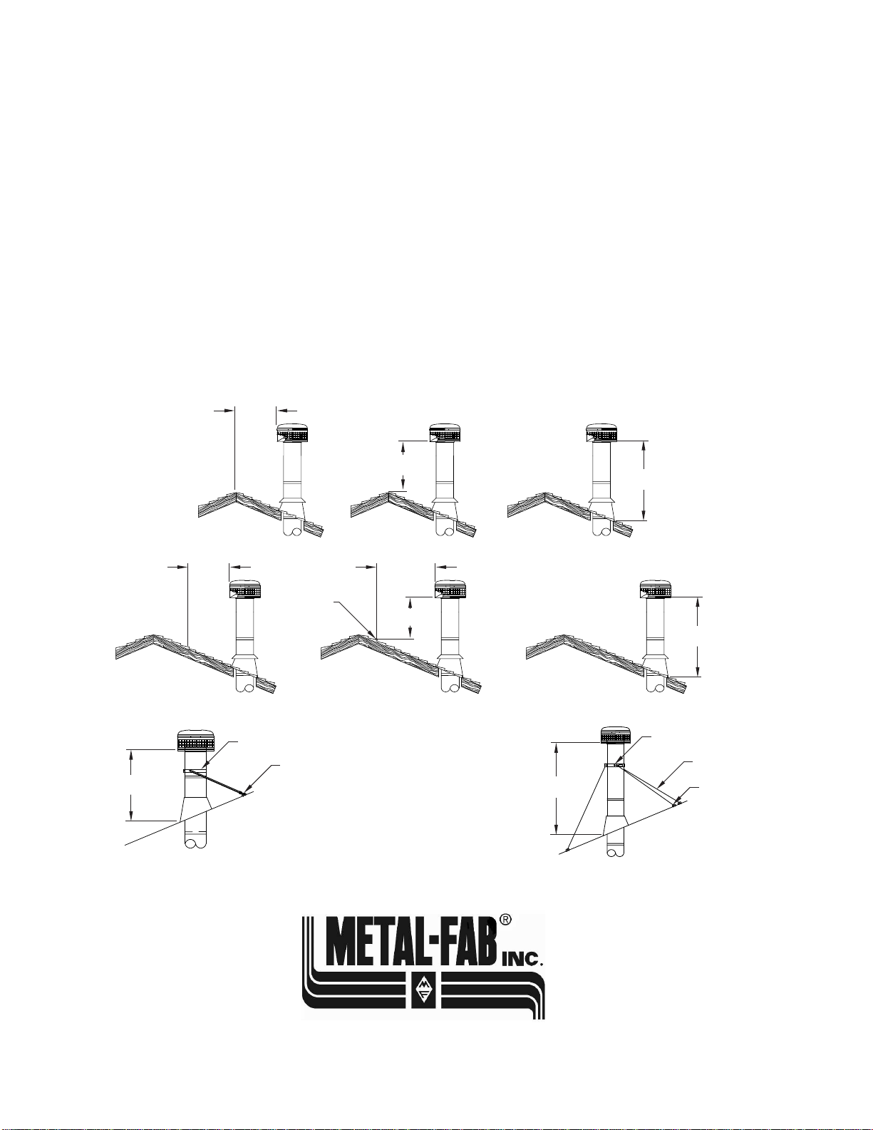
TERMINATION
Major building codes specify a minimum chimney height above
the roof top. These specications are summarized in what is
known as the “Ten Foot Rule”. This rule states:
If the horizontal distance from the side of the chimney to the peak
of the roof is 10 feet or less, the top of the chimney must be at
least 2 feet above the peak of the roof, but never less than 3 feet
in overall height above the highest point where it passes through
the roof (FIG. 20).
If the horizontal distance from the side of the chimney to the peak
of the roof is more than 10 feet, a chimney height reference point
is established on the surface of the roof a distance of 10 feet
from the side of the chimney in a horizontal plane. The top of the
chimney must be at least 2 feet above this reference point, but
never less than 3 feet in height above the highest point where it
passes through the roof (FIG. 21)
These chimney heights are necessary in the interest of safety and
do not ensure smoke free operation. Trees, buildings, adjoining
roof lines, adverse wind conditions, etc., may create need for a
taller chimney should smoking occur.
Additional support is required above the roof if the chimney
height exceeds four (4) feet.
Select the proper support for your application, using either a
roof brace (FIG. 22) or a support band with guy wires (FIG. 23)
L944 FIG22
L944 FIG23
FIG. 20
IF 10
FEET OR
LESS
L944 FIG21
THEN BUT
MUST BE AT
LEAST 2 FEET NEVER LESS
THAN 3 FEET
FIG. 21
IF 10
FEET OR
MORE
MUST BE AT
LEAST 2 FEET NEVER LESS
THAN 3 FEET
10 FEET
FIG. 22
FOR HEIGHTS
FROM 4’ TO 8’
REFERENCE
POINT
ROOF
TGRB ROOF BRACE
LAG BOLTS
FIG. 23
ROOF
TGSB SUPPORT BAND
LAG BOLT
GUY WIRES
(1/4” MINIMUM CABLE
DIAMETER)
FOR HEIGHTS EXCEEDING
8’ UP TO 20’
THEN BUT
8
1. Form the attachment band around the chimney, and clamp
in place at the desired height using bolt and nut provided.
2. Loosely attach the support legs to the bolts on the
attachment band using hardware provided.
3. Position the support legs as shown in FIG. 22. The length
of the support legs can be adjusted by loosening the bolt on
the leg clamp.
4. Secure legs to roof using screws provided. Seal screw holes
to prevent roof leaks.
5. Tighten all hardware.
TG ROOF BRACE INSTALLATION
Other manuals for Temp/Guard
1
This manual suits for next models
4
Table of contents
Other Metal Fab Fan manuals


Popular Fan manuals by other brands

Minka-Aire
Minka-Aire F601 Acero instruction manual

Hunter
Hunter Grand Cayman Owner's guide and installation manual

Hunter
Hunter Tribeca 82021 Parts guide

OBH Nordica
OBH Nordica 1385 Instructions of use

Envirovent
Envirovent SLIMLINE 300 Installation guide for engineer / installer

Tesco
Tesco DF98 user guide


