Metal Fab CORR/GUARD User manual

CORR/GUARD
INSTALLATION INSTRUCTIONS
This symbol on the nameplate
means this product is listed by
Underwriters Laboratories Inc.
Tested to UL1738 / CAN / ULCS636-1995
Listing No. MH26687
Testing No. 11EN
Corr/Guard
PRESSURE RATED VENTING SYSTEM
AL29-4C®STAINLESS STEEL
CONDENSING APPLIANCES
CAT. II, III, IV APPLIANCES
FUME EXHAUST
3”(76mm)-24”(610mm) DIAMETERS
IMPORTANT:DONOTINSTALLWITHOUTFIRSTREADINGTHESEINSTRUCTIONS
VERY CAREFULLY.
EXAMINE ALL COMPONENTS FOR POSSIBLE SHIPPING DAMAGE BEFORE
INSTALLATION. PROPER JOINT ASSEMBLY IS ESSENTIAL FOR A SAFE
INSTALLATION. FOLLOW THESE INSTRUCTIONS EXACTLY AS WRIT-
TEN. CHECK SEVERENESS OF JOINTS UPON COMPLETION OF ASSEM-
BLY. THIS VENTING SYSTEM MUST BE FREE TO EXPAND AND CONTRACT.
SUPPORT SYSTEM IN ACCORDANCE WITH THESE INSTRUCTIONS. CHECK
FOR UNRESTRICTED MOVEMENT THROUGH WALLS CEILINGS, AND ROOF
PENETRATIONS. DIFFERENT MANUFACTURERS HAVE DIFFERENT JOINT
SYSTEMS AND ADHESIVES. DO NOT MIX PIPE, FITTINGS, OR JOINING
METHODS FROM DIFFERENT MANUFACTURERS.
METAL-FAB, INC. P.O. BOX 1138, WICHITA, KS 67201-1138
C US
2
CORR/GUARD VENTING SYSTEM INSTALLATION
INSTRUCTIONS
Corr/Guard is manufactured as a Single Wall vent designated as CGSW;
and Double Wall vent designated as CG. Corr/Guard is a special stainless
steel venting system for gas-red appliances listed as Cat. II, III & IV or in
Canada, Type BH Gas Venting Systems per ULC-636, with rated operating
temperature of 550°F (287°C), Corr/Guard is rated for positive pressure of
10” (254mm) w.c. for 3” (76mm) diameter through 5” (127) diameter and 6”
(152mm) w.c. for 6” (152mm) diameter through 24” (610mm) diameter. Refer
to TABLE 1 for Operating Temperatures and Clearance to Combustibles.
Metal-Fab, Inc. recommends the system be inspected once a year by a
qualied service technician.
Venting system design may be limited by appliance performance. Consult
appliance installation instructions to determine proper sizing and limitations
suchasmaximumhorizontallengthandheight,maximumnumberofelbowsor
offsets, connecting two or more appliances to a common venting system, and
otherlimitationsthatmayaffectdesignandinstallation.It is the responsibility
of the installer to contact local building and re ofcials concerning
any installation restrictions and/or inspection requirements that may
apply. Permits may be required before starting an installation. Installation is to
be in accordance with local building code requirements and National Codes:
USA– NFPA54ANSI-Z223.1 or NFPA 211. In Canada – CAN/CGA-B149.1 or
CAN/CGA-B149.2 Propane Installation Code as applicable.
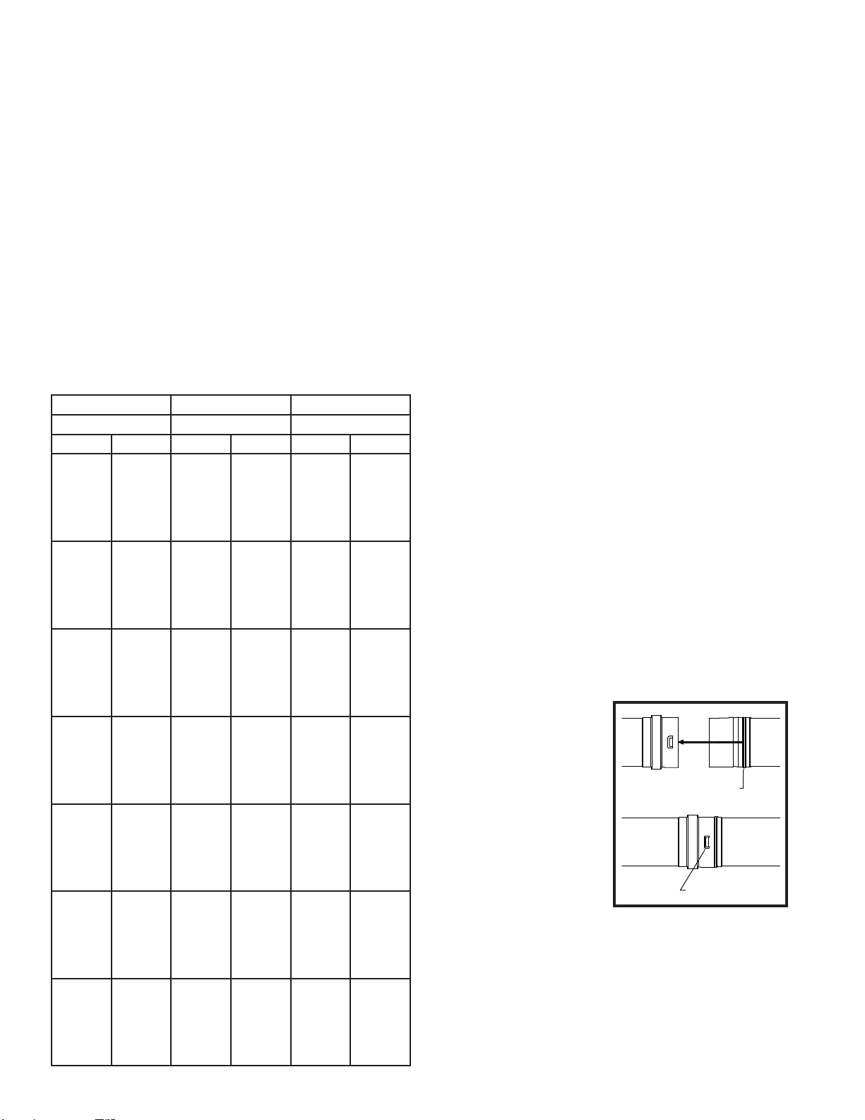
TABLE 1
GENERAL
Corr/Guard is to be installed in accordance with these installation instructions
and those of the appliance manufacturer. For conditions and applicable
restrictions not specically mentioned herein, contact building or re
ofcials having jurisdiction in your area. The following is a guide to assist a
professional installer:
• Proper operation of the venting system and appliance is dependant on the
use of all parts specied by Metal-Fab for use in the particular installation.
System performance may be affected if the proper assembly of all required
parts is not accomplished.
• Refer to appliance’s instructions to determine proper sizing and connection
of the venting system to the appliance.
• Corr/Guard Model CG double wall vent may be used with Model CGSW
single wall vent within the same vent system.
• Tee sections should only be used in conjunction with a drain on appliances
tested for use with a drain, or if allowed by the appliance manufacturer for
multiple appliance connections.
• If required by the appliance manufacturer, a drain tting must be located
as close as possible to the appliance ue outlet. Unless a drain tting is
supplied with the appliance, install only a Corr/Guard Drain Fitting.
• More than one Category II, III or IV appliance may not be connected into
the same vent system, unless the appliance manufacturer specically
approved such a system and the appliances are designed for multiple
venting. Cat. II, III or IV appliances MAY NOT share any part of their vent
system with a natural draft appliance.
• Check the joints and seams for gas tightness when using the venting
system with a Cat. III or Cat. IV appliance.
• Except for installation in one and two family dwellings, a venting
system that extends though any zone above that on which the connected
appliance is located shall be provided with an enclosure having a re
resistance rating equal to or greater than that of the oor or roof assemblies
through which it passes.
• Corr/Guard shall not be routed into, through, or within any other vent, such
as an existing masonry or factory-built chimney ue that is connected to
another appliance.
• WARNING! Do not place or install insulation in any required clearance
spaces surrounding the venting system.
• Enclosure of exterior mounted venting systems below the rooine
is recommended to limit condensation and protect from mechanical
damage.
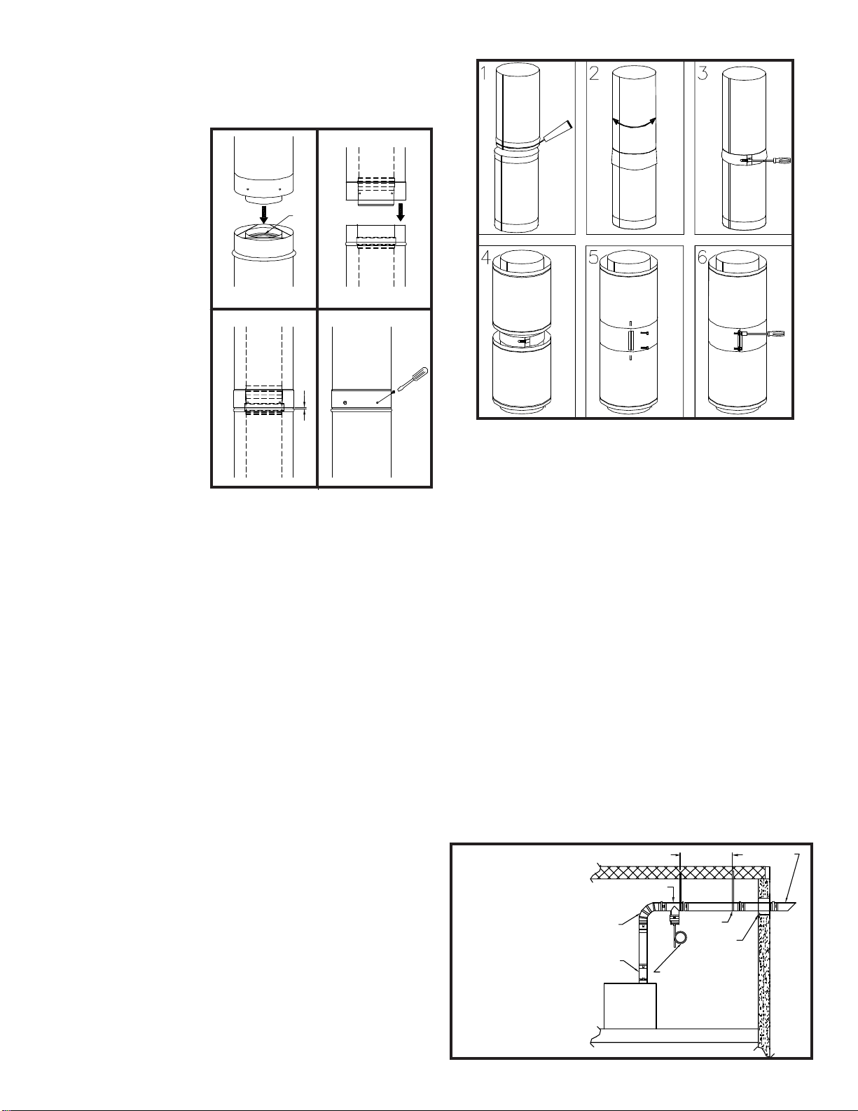
JOINT ASSEMBLY
3”- 5” (76mm - 127mm) DIAMETER CGSW
Each Corr/Guard vent component contains a seal gasket on the female
end of the vent joint and locking tabs. Mechanical fastening of the joint
is automatic and requires no tools. Visually check the gasket for proper
location within the pipe bead during assembly or ue gases could leak,
resulting in carbon monoxide poisoning. Assembly of joints is shown
below:
1. Insert the male end of the vent
pipe into the adjoining female
ventsectionuntilthebeadofthe
male joint stops at the edge of the
female joint.
2. When properly inserted to
the fullest extent, the integral
locking tabs will snap into
place, securing the joint..
Before Proceeding, verify
that all locking tabs are
engaged for each joint
assembly.
Rated Operating Minimum Clearance Minimum Clearance
Temperatures Enclosed Unenclosed
Pipe Dia. Temp. Horiz. Vert. Horiz. Vert.
3”-5”
(76mm -
127mm)
(CG)
Double
Wall
300°F
(149°C)
480°F
(249°C)
550°F
(288°C)
3”
(76mm)
6”
(152mm)
N/A
1”
(25mm)
1”
(25mm)
N/A
1”
(25mm)
1”
(25mm)
1”
(25mm)
1”
(25mm)
1”
(25mm)
1”
(25mm)
3”&4”
(76mm -
102mm)
(CGSW)
Single
Wall
400°F
(204°C)
480°F
(249°C)
550°F
(288°C)
8”
(203mm)
8”
(203mm)
N/A
4”
(102mm)
4”
(102mm)
N/A
1”
(25mm)
2”
(51mm)
2”
(51mm)
1”
(25mm)
2”
(51mm)
2”
(51mm)
5”
(127mm)
(CGSW)
Single
Wall
400°F
(204°C)
480°F
(249°C)
550°F
(288°C)
N/A
N/A
N/A
6”
(152mm)
6”
(152mm)
N/A
1”
(25mm)
2”
(51mm)
2”
(51mm)
1”
(25mm)
2”
(51mm)
2”
(51mm)
6”-12”
(152mm -
305mm)
(CG)
Double
Wall
480°F
(249°C)
550°F
(288°C)
N/A
N/A
1”
(25mm)
N/A
1”
(25mm)
1”
(25mm)
1”
(25mm)
1”
(25mm)
14”-24”
(356mm -
610mm)
(CG)
Double
Wall
480°F
(249°C)
550°F
(288°C)
N/A
N/A
1”
(25mm)
N/A
5”
(127mm)
5”
(127mm)
1”
(25mm)
5”
(127mm)
6”-12”
(152mm -
305mm)
(CGSW)
Single
Wall
480°F
(249°C)
550°F
(288°C)
N/A
N/A
N/A
N/A
2”
(51mm)
2”
(51mm)
2”
(51mm)
2”
(51mm)
14”-24”
(356mm -
610mm)
(CGSW)
Single
Wall
480°F
(249°C)
550°F
(288°C)
N/A
N/A
N/A
N/A
6”
(153mm)
6”
(153mm)
6”
(153mm)
6”
(153mm)
VERIFY THAT TABS "SNAP"
INTO LOCKING POSITION.
INSERT MALE END UNTIL THE END OF
THE FEMALE PROFILE MAKES CONTACT
WITH THE MALE PROFILE BEAD.
FIG. 1
3
JOINT ASSEMBLY
3”- 5” (76mm - 127mm) DIAMETER CG
Connections between vent and ttings are male/female type. The inner
duct is sealed with an integral seal gasket and the joint is mechanically
secured via the overlapping outer wall of the double wall pipe.
Joints are assembled per
the following steps:
1. Before assembly,
observe that the seal
gasket is located
within the female
inner pipe joint. Locate
next pipe or tting with
male inner pipe joint
and insert to begin
engagement of inner
pipe joint.
2. As the joint further
engages, align the male
and female ends of the
outer wall of each pipe
so that they begin to
engage as the pipes
are further pushed
together.
3. Pipe joint is fully
engaged when the
female end of the outer
pipe comes in contact
(or is at least within
3/16” 5mm) to the base
of the bead on the male
end of the adjoining
vent pipe.
4. When possible look within the pipe assembly to verify that no sign of
seal gasket is showing. Complete the joint assembly by securing
the joint using #8 x 1/2” sheet metal screws (3 per joint) at each pre-
punched hole on the female end of each joint.
WARNING:Sheet metal screwsarefor Double Wall CORR/GUARDouter
wall only. Never use screws, rivets or other fasteners to penetrate the
inner pipe wall.
6”- 24” (152mm - 610mm) DIAMETER CGSW & CG
Connections between vent and fittings are male / female type, sealed
with silicone sealant and secured with a profiled closure band.
Connection Tips (See FIG. 3):
1. Clean male and female joint ends to remove oil and
contaminants with alcohol pads provided. Apply a ¼ inch
(6.4mm) bead of sealant to the male connection
approximately ¼ inch (6.4mm) below the edge. Also apply ¼
inch (6.4mm) bead of sealant (approx. 2 inches long) along
the male joint at the overlap of the welded seam.
2. Insert male end into female, twisting slightly, to ensure
even distribution of sealant. Be sure sections are seated.
Inspect the joint to ensure that vent gases will not escape. If
necessary, apply additional sealant to any visible voids
around the joint and smooth it into crevices.
3. Align profiled closure band snugly around the joint section.
Insert tongue into gear clamp and tighten with 3/8-inch hex
drive socket.
IMPORTANT: Profiled Vent connection band is formed to fit exactly
over the joint section. This part is not symmetrical and should be
installed in the proper orientation for maximum seal and support.
Allow sealant to cure for a minimum 24 hours before operating the
appliance. Any adhesives used in the assembly of the system are to
be used within their marked time limitations.
4. For CG (double wall) joint installations, first complete steps
1 thru 3 as shown above.
5. Once the inner vent joint has been connected, locate the
casing band around the casing, positioning the band
between the formed beads on either casing.
6. Tighten the band snugly around the vent casings using
3/8-inch hex drive socket.
SEAL
GASKET
1 2
43
3
16" GAP (MAX.)
FIG. 2
FIG. 3
INSTALLATION
HORIZONTAL VENTING
A venting system that exits through a side wall shall:
• Terminate not less than 12 inches (305 mm) above the ground.
• Be located above the snow line in geographical areas where snow
accumulates.
• Not be located in trafc areas such as walkways unless the venting system
is at least 7 feet (2.1 m) above the ground.
When an appliance incorporates a combustion air inlet system, the venting
system shall terminate:
• 6 feet (1.8m) or more from the combustion air intake of any appliance.
• More than 3 feet (0.9m) from any other building opening, gas utility meter,
service regulator or the like.
• Less distance is permitted if specied in the appliance’s installation
instructions.
For horizontal venting (Typical Installation Shown in FIG. 4):
• Means shall be provided for draining condensate. Due to ice build up and
blockage, it is required that proper sloping be employed when the vent is
installed horizontally.
• Any portion of a horizontally installed vent shall have a slope (upwards for
Cat. II, III or IV appliances or downwards for Cat. III or IV appliances) not
less than 1/4 inch (6.4 mm) every 12 inches (305 mm) to prevent collection
of condensate at any location in the assembly.
• Use non-combustible hanger straps a minimum of every 7 feet (2.1 m) for
3”- 5” (76mm - 127mm) diameters (CG & CGSW) and every 6 feet (1.8 m)
for 6” - 24” diameters (CG & CGSW) (See TABLE 2) to support the vent
system from ceiling joints or other solid structures. WARNING! Do not
puncture vent system!
• Vent must not sag or dip, providing areas for condensate to collect.
SEETABLE 2
APPLIANCE
TERMINATION
APPLIANCEADAPTER
ELBOW
HORIZONTAL DRAIN TEE
OR DRAIN FITTING
HANGER
STRAP
WALL
PENETRATION
ROUTE TO DRAIN.
DISPOSE OF CONDENSATE
ACCORDING TO LOCAL CODE.
Side
Wall
Installation
FIG. 4

4
WALL PENETRATION
1. Prior to installation, determine proper location of wall thimble so that a
minimum slope of 1/4” (6mm) per foot is maintained in the horizontal
section of vent to ensure proper ow of condensation.
2. Prepare the wall by cutting a square opening per TABLE 3. (Opening size
adequate to insert Wall Thimble components)
3. Install the Wall Thimble by inserting the larger of the two parts on the
appliance (interior) side.
4. Next, apply abeadofsealantaroundthe edgesoftheexterior(smallerofthe
two parts) Wall Thimble component. Then install this part of the Wall
Thimble by inserting the smaller collar into the other component from the
previous step.
NOTE: The two horizontal cylinders of the Thimble must engage a
minimum of two inches.
5. Fasten both sides of the Wall Thimble using screws or nails.
6. Once the Thimble is installed, Corr/Guard vent pipe can be inserted into the
Thimble by inserting the male end rst. (See FIG. 5, 6 & 7).
7. Assemble Corr/Guard vent from the Wall Thimble section back to the
appliance.
8. Install a horizontal termination to complete the assembly.
9. Once assembly is completed, apply a bead of high-temp sealant around the
pipe and the exterior plate of the Thimble to protect against weather.
WARNING! Appliance outlet temperature shall not exceed 480°F (249°C)
for venting systems that penetrate walls constructed of combustible
materials.
TO APPLIANCE
TO TERMINATION
INSIDEBUILDING
SURFACE
OUTSIDE BUILDING
SURFACE
WOOD STUD
2" MIN.
OVERLAP
SEALANT
FIG. 5
Wall Thimble Installation
3”- 5” (76mm-127mm) CGSW
SUPPORT PIPE DIA. / MODEL DISTANCE
BETWEEN
SUPPORTS
HORIZONTAL RUNS 3”-5” (76mm-125mm) CG & CGSW 7’ (2.13 m)
6”-24” (152mm-610mm) CG&CGSW 6’ (1.83 m)
HORIZONTAL 3”-5” (76mm-125mm) CG & CGSW 7’ (2.13 m)
BETWEEN ELBOWS 6”-24” (152mm-610mm) CG&CGSW 6’ (1.83 m)
FIG. 6
Wall Thimble Installation
3”- 5” (76mm-127mm) CG
TO APPLIANCE
CASING END CLOSURE
SEALANT
TERMINATION
FIG. 7
Wall Thimble Installation
6”- 24” (152mm-610mm) CG & CGSW
RADIATIONSHIELD
(SINGLE WALL)
CASING END
CLOSURE
TERMINATION
SEALANT
PIPE DIAMETER FRAMING DIMENSIONS (MINIMUM)
3”-5” (76mm-127mm)
CGSW (SINGLE WALL) (PIPE DIA.+5”) x (PIPE DIA.+5”)
(PIPE DIA.+127mm) x (PIPE DIA.+127mm)
3”-5” (76mm-127mm)
CG (DOUBLE WALL) (PIPE DIA. + 5”) X (PIPE DIA. + 5”)
(PIPE DIA.+127mm) x (PIPE DIA.+127mm)
6”-24” (152mm-610mm)
CGSW (SINGLE WALL) (PIPE DIA. + 6”) X (PIPE DIA. + 6”)
(PIPE DIA.+152mm) x (PIPE DIA.+152mm)
6”-24” (152mm-610mm)
CG (DOUBLE WALL) (PIPE DIA. + 6”) X (PIPE DIA. + 6”)
(PIPE DIA.+152mm) x (PIPE DIA.+152mm)
TABLE 3TABLE 2
VERTICAL VENTING
• Enclose residential exterior vent systems below the roof line or use double
wall Corr/Guard (CG) to limit condensation due to cool down of ue
gases.
• Unless installed in a re rated shaft, a re stop / vertical support is required
when penetrating oors and ceilings.
• Vertical supports are to be used after each transition to vertical. Refer to
TABLE 4 for support methods and heights.
• When assembling Corr/Guard vent, always align “UP” arrow away from the
appliance.
• The total equivalent length from the appliance outlet to the termination
shall not exceed maximum length specied by the appliance
manufacturer’s installation instructions.
• Vertical terminations must terminate no less than 2’ (0.61 m) above the
roof or any wall or vertical structure closer than 8’ (2.4 m). A vent cap or
other equivalent termination is required to keep rain or debris out of the
vent. TABLE 4
SUPPORT METHODS PIPE SIZE/MODEL MAX.HEIGHT
PLATE SUPPORTS 3”-24” (76mm-610mm)
3”-12” (76mm-305mm) CGSW
14” - 24” (356mm-610mm) CGSW
30’ (9.1m)
30’ (9.1m)
20’ (6.1m)
WALL BAND 6”-16” (152mm-406mm) CG
6”-12” (152mm-305mm) CGSW 8’ INTERIOR
8’ INTERIOR
ROOF SUPPORTS
(PLATE SUPPORT
USED ON ROOF)
3”-24” (76mm-610mm) CG
3”-24” (76mm-610mm) CGSW 5’ (1.5m)
5’ (1.5m)
WALL SUPPORTS
3”-5” (76mm-127mm) CG
3”-5” (76mm-127mm) CGSW
6”-24” (152mm-610mm) CG
6”-24” (76mm-610mm) CGSW
3”-24” (76mm-610mm) CG
3”-24” (76mm-610mm) CGSW
6’ (1.8m) EXTERIOR
6’ (1.8m) EXTERIOR
8’ (2.4m) EXTERIOR
8’ (2.4m) EXTERIOR
30’ (9.1m) INTERIOR
30’ (9.1m) INTERIOR
*Wall Hanger 3”-5” CG/CGSW alignment only, not a vertical support.
1. Starting at the appliance outlet, attach the rst section or appliance
adaptor. (See FIG. 8 & 9 for typical installation.)
2. Continue assembly of pipe
until nearing a ceiling
penetration. Locate and cut
hole in oor and ceilings that
will be penetrated. Hole size
must maintain minimum listed
clearances per TABLE 1.
3. Install a restop support
when penetrating the ceiling
to support the vertical run of
the vent system.
4. When installing a restop in
the attic, the restop or
support plate is located
on top of the joist to prevent
insulation from falling into
the joist.
5. Continue with the vent
penetrating the roof. At the
roof, the opening must
maintain a minimum of
clearance to combustibles
as specied in these
instructions and on the
labeled vent product.
6. Above the roof, a ashing
and storm collar are required.
Use high temperature sealant
to seal the storm collar to the
vent so that rain will not
penetrate the roof opening
(See FIG. 10, 11 & 12).
APPLIANCE
APPLIANCE
ADAPTOR TO DRAIN
DISPOSE OF
CONDENSATES
ACCORDINGTO
LOCAL CODES
HORIZONTAL
DRAIN TEE OR
DRAINFITTING
WITH TEE
HANGER STRAP
FIRESTOP
SUPPORTCLAMP FIRESTOP
FLASHING
STORMCOLLAR
RAINCAP
SEE TABLE 2
FIG. 8
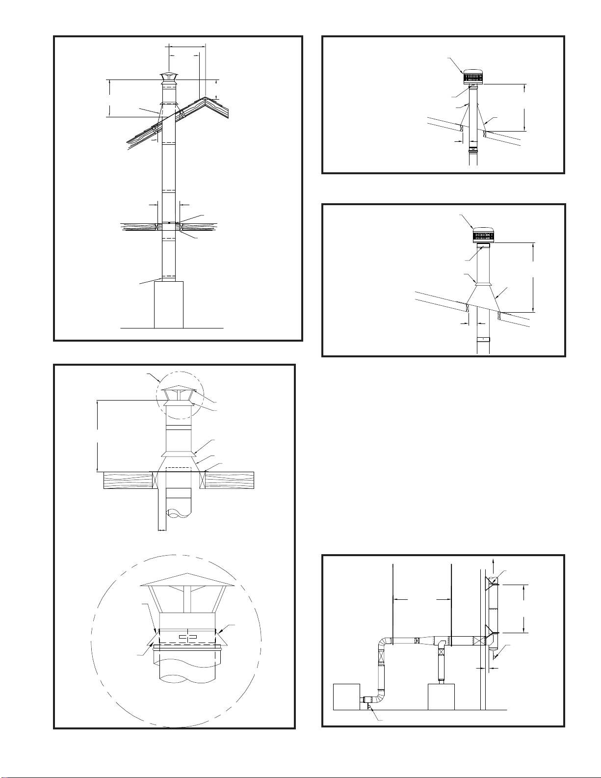
5
EXTERIOR INSTALLATION
1. There may be installations where CG & CGSW run vertically - exterior
to the building and a wall band support is needed. A wall band support
is used to secure the vent system to a wall while maintaining the minimum
clearance to combustible construction (See FIG. 13).
2. Wall band supports must be securely astened to a solid member of the
building using appropriate fasteners for various building materials such
as wood, steel siding or masonry.
3. Exterior mounted wall band supports are to be vertically spaced per
TABLE 4.
4. Wall band supports are designed to be fastened to the vent by means of
clamping externally to the vent. No screws are to puncture the vent wall.
WARNING: Do not rivet or screw supports to the vent or otherwise
puncture the vent wall.
WARNING: Do not place any type of insulation in any required
clearance spaces surrounding the vent system.
JOINT
CLAMP
CLOSURE
RING
ALLOW AIR
SPACE
BETWEEN
END OF
CASING AND
STORM COLLAR
AS SHOWN
CAP DETAIL
FIG. 12
6”- 24”
CG & CGSW
CAP
CLOSURE RING
STORM COLLAR
FLASHING
FOR CLEARANCE TO
COMBUSTIBLES
SEE TABLE 1.
5'(1.5M) MAX.
UNLESS SUPPORTED
BY GUY WIRES
PLATE SUPPORT
USED AT ROOF
SEE CAP
DETAIL
PITCHED
FLASHING
STORM COLLAR
RAINCAP
SEE TABLE 1 FOR
CLEARANCES
5' (1.5M) MAX. UNLESS
SUPPORTED BY GUY
WIRES
LOCKING TAB
FIG. 10
Roof Installation
3”- 5” CGSW
DRAFT HOOD CONNECTOR(IF REQUIRED)
SEE APPLIANCE INSTRUCTIONS APPLIANCE
FIRESTOP-
LOCATE OVER JOIST TO MAINTAIN
CORRECT CLEARANCE FROM VENT
CASING TO COMBUSTIBLE MATERIAL
PLATE SUPPORT- SEE TABLE 4 FOR MAXIMUM
DISTANCE BETWEEN SUPPORTS
MAINTAIN CLEARANCE TO
CHIMNEY
3' (.9M) MIN.
FLASHING
COMBUSTIBLE THROUGH JOIST AREA
SEE TABLE 1.
MORE THAN 10' (3m)
10' (3m)
2' MIN. HEIGHT ABOVE ANY
ROOF SURFACE WITHIN
10 FT. (3.1m) HORIZONTAL
FOR CLEARANCES
SEE TABLE 1
FIG. 9
PITCHED
FLASHING
STORM COLLAR
RAINCAP
SEE TABLE 1 FOR
CLEARANCES
5'(1.5M) MAX. UNLESS
SUPPORTED BY GUY
WIRES
ATTACH BY USING
#8x1/2" SCREWS
FIG. 11
Roof Installation
3”- 5” CG
TO DRAIN
BOILER
1BOILER
2
PLUMBERS STRAP
TO DRAIN
WALL BAND
SUPPORT
FOR DISTANCE
BETWEEN SUPPORTS SEE TABLE 4
FOR DISTANCE
BETWEEN SUPPORTS
SEE TABLE 1
FOR CLEARANCES
TO TERMINATION
SEE TABLE 2
FIG. 13

6
VARIABLE LENGTH
For installations that require non-standard vent lengths, Corr/Guard
Variable Length vent sections may be used. The vent section consists of
an inner conduit that slip fits into the outer conduit, a compression band,
or integral clamp and an outer casing for double wall only.
3”- 5” (76mm-127mm) CG & CGSW
To install the VL vent section, first install the inner pipe section by
connecting the male section to the adjoining double or single wall vent
pipe. Insert male section until the bead of the joint stops at the edge of
the female end of the vent section.
Next, expand the length of the inner pipe to the necessary length and
tighten the integral clamping band using a hex drive or screw driver. The
VL’s are adjustable from 7 1/2” to 22” (191mm to 559mm). Continue with
the next section of vent, making sure to fully join the inner pipe of the
vent from the female end of the VL vent.
When installing double wall, finish the VL vent assembly by installing the
outer casing wall around the VL inner pipe section. Secure the casing
by installing #8x1/2” sheet metal screws at prepunched holes (See FIG.
14).
FIG. 15
WARNING: Variable Length sections are not intended to be
subjected to vertical force loads. Use appropriate support
methods.
Supplementary support is required when installing offsets, elbows and
non-vertical runs to prevent unacceptable stresses. Do not allow vent to
sag or deflect from intended flow line during installation.
WARNING: Do not place any type of insulation in any required
clearance spaces surrounding this Vent System.
CONDENSATE DRAINS
If an appliance does not supply a condensate drain and one is required
per the appliance manufacturer’s instructions or local codes, install a
drain fitting in the horizontal conduit, as close as possible to the appli-
ance vent collar.
WARNING: NEVER INSTALL A DRAIN IN A SYSTEM WITH AN
APPLIANCE NOT INVESTIGATED FOR USE WITH A CONDENSATE
DRAIN.
Corr/Guard drain fittings contain a 1/2” (13mm) diameter drain tube that
should be located at the bottom of the vent or fitting when installed prop-
erly. A drain hose must be attached to the tube and a trap loop must be
formed into the drain hose. The trap loop should be at least four times the
appliance’s rated stack pressure in inches of water column or 6 inches
(153mm), whichever is less. (See FIG. 16)
When the Corr/Guard vent system is installed the system must be pres-
sure checked to for tightness. Repair any joint leaks by disassembling
and resealing following the guidelines in the Joint Assembly section of
these instructions. Replace any defective component.
The Corr/Guard ventilation system, manufactured by Metal-Fab, Inc..
is constructed to exacting standards. The proper operation of this vent
system is dependent on the use of correct components, proper sizing,
quality of installation, and guidelines and limitations expressed by the
appliance manufacturer.
TUBING
TRAP LOOP
(4X STACK PRESSURE)
FIG. 16
6”- 24” (152mm-610mm) CG & CGSW
To install the VL, first apply a heavy bead of P077 Sealant into the inner
vent groove. Then slide the inner vent into the outer vent. Locate into
position and adjust to proper length. Follow Joint Assembly Details on
PAGES 2 & 3. Apply a bead of P077 Sealant at the joint of inner and
outer vent and attach compression band. The 6” VL is adjustable from
7½” to 10” (191mm to 254mm) and the 12” (305mm) VL is adjustable
from 13½” to 22” (343mm to 559mm). When installing double wall, cut
outer jacket to fit between the mating vent and install using sheet metal
screws (supplied) (See FIG 15).
INNER FLUE
CASING JACKET
INTEGRAL CLAMP
FIG. 14
COMPRESSION
BAND
OUTER
JACKET
FOR CG
ONLY
GROOVE
OUTER CONDUIT
INNER CONDUIT
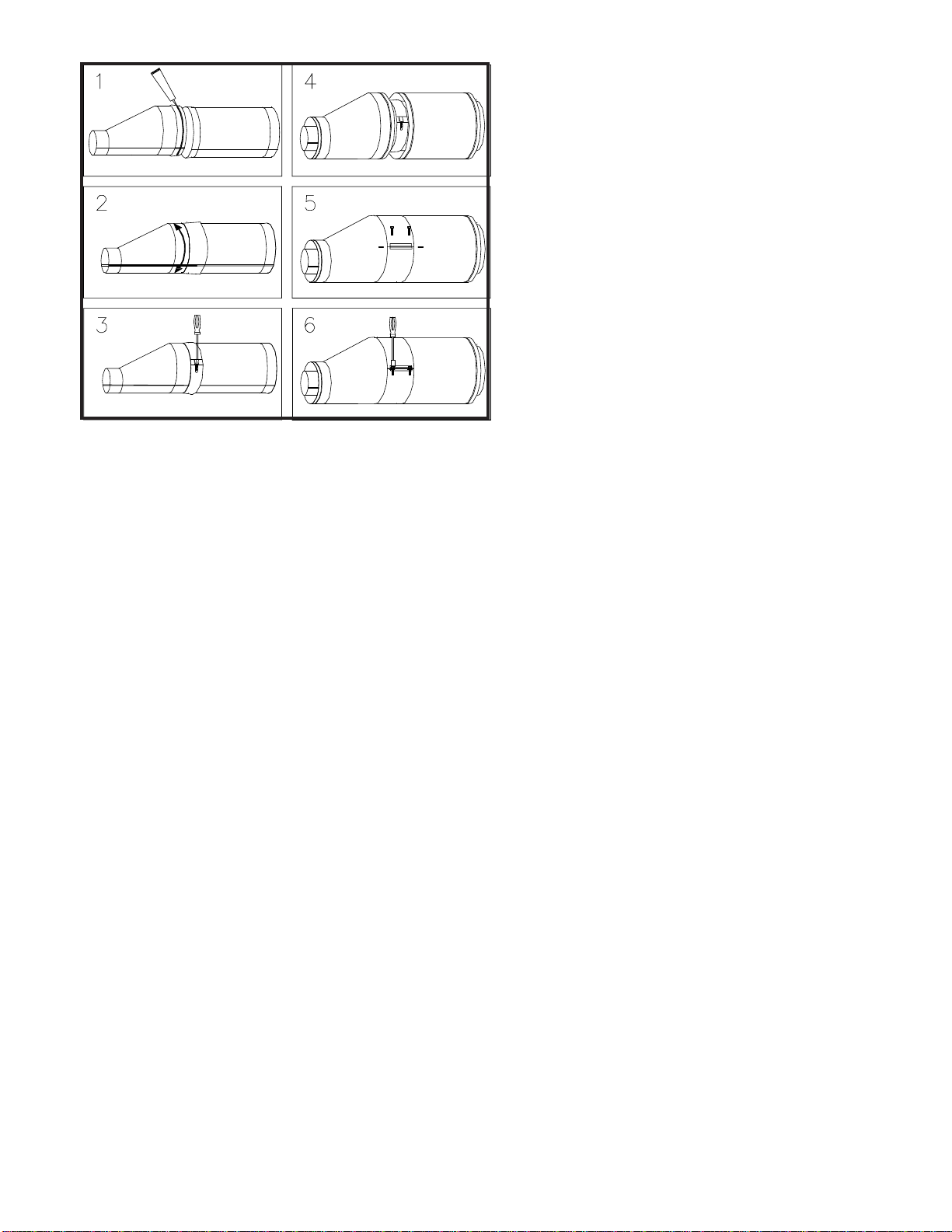
SMALL DIAMETER CGSW & CG TO CGSW & CG
Connections between vent and fittings are male / female type, sealed
with silicone sealant and secured with a profiled closure band. (See FIG.
17)
Connection Tips:
1. Clean male and female joint ends to remove oil and
contaminants with alcohol pads provided. Apply a ¼ inch
(6.4mm) bead of sealant to the male connection
approximately ¼ inch (6.4mm) below the edge. Also apply ¼
inch (6.4mm) bead of sealant (approx. 2 inches long) along
the male joint at the overlap of the welded seam.
2. Insert male end into female, twisting slightly, to ensure
even distribution of sealant. Be sure sections are seated.
Inspect the joint to ensure that vent gases will not escape.
If necessary, apply additional sealant to any visible voids
around the joint and smooth it into crevices.
3. Align profiled closure band snugly around the joint section.
Insert tongue into gear clamp and tighten with 3/8-inch hex
drive socket.
IMPORTANT: Profiled Vent connection band is formed to fit exactly
over the joint section. This part is not symmetrical and should be
installed in the proper orientation for maximum seal and support.
Allow sealant to cure for a minimum 24 hours before operating the
appliance. Any adhesives used in the assembly of the system are to
be used within their marked time limitations.
4. For CG (double wall) joint installations, first complete steps
1 thru 3 as shown above.
5. Once the inner vent joint has been connected, locate the
casing band around the casing, positioning the band
between the formed beads on either casing.
6. Tighten the band snugly around the vent casings using
3/8-inch hex drive socket.
7
MAINTENANCE INSTRUCTIONS
As with all vents, the Corr/Guard vent system should be inspected at
least annually for the presence of deposits or debris and any accumula-
tion should be removed. The vent system should also be inspected at
regular periods for signs of leakage of condensate or combustion prod-
ucts at any joints.
If the vent system incorporates a drain hose from either an inline fitting or
from a drain tee, the hose must be inspected periodically to ensure that
water is in the trap loop. If a proper trap loop is not maintained, exhaust
from the connected appliances may accumulate in the building area.
Where the duct is installed outside the building, the aluminized steel
outer casing must be primed and painted. The painted surface should
be maintained regularly to prevent possible deterioration of the casing
surface. The use of stainless steel outer casing negates the need for
painting.
IMPORTANT: The listing for this product is void if components
other than those supplied as Listed Components by Metal-Fab,
Inc. are used. All warranties, stated or implied, are void if this
product and the appliances to which it is connected are not
installed in accordance with their respective instructions and local
code requirements.
FIG. 17

8
P.O. Box 1138 • WICHITA, KANSAS 67201
(316)943-2351 • fax (316)943-2717
©2008 Metal-Fab, Inc. Form No. L1704 10/08
8367
Table of contents
Other Metal Fab Fan manuals


