Metal Fab CG User manual
CORR/GUARD
DOUBLE WALL
INSTALLATION INSTRUCTIONS
CG AL29-4C Stainless Steel - Pressure Rated Venting System
CGV 444 Stainless Steel - Pressure Rated Venting System
IMPORTANT: DO NOT INSTALL WITHOUT FIRST READING THESE
INSTRUCTIONS VERY CAREFULLY.
Corr/Guard, manufactured by Metal-Fab, Inc. is a special stainless steel
venting system for gas-red appliances listed as Cat. II, III & IV or in Canada,
Type BH Gas Venting Systems per ULC-636, with rated operating temperature
of 550°F (287°C), and rated for positive pressure of 15” w.c. Metal-Fab,
Inc. recommends the system be inspected once a year by a qualied service
technician.
Examine all components for possible shipping damage before
installation. Proper joint assembly is essential for a safe installation.
Follow these instructions exactly as written. Check severe stress of
joints upon completion of assembly. This venting system must be free
to expand and contract. Check for unrestricted movement through walls,
ceilings and roof penetrations. Different manufacturers have different
joint systems and adhesives. Do not mix pipe, ttings or joining methods
from different manufactures.
Corr/Guard Double Wall vent is designated as Model CG or CGV and may be
used to vent any appliance whereAL29-4C or 444 vent material is specied in
the appliance manufacturers installation instructions and performance criteria
is within the limitations in these instructions.
Venting system design may be limited by appliance performance. Consult
appliance installation instructions to determine proper sizing and limitations
such as maximum horizontal length, maximum height, maximum number of
elbows or offsets, connecting two or more appliances to a common venting
system, and other limitations, which may affect design and installation.
The authority having jurisdiction (such as gas inspection authority, municipal
building department, re department, re prevention bureau, etc.) should
be consulted before installation to determine the need to obtain a permit.
NOTE: The Corr/Guard venting system is rated for 15” w.c. based on tests
requiring an internal pressure 2-1/2 times the rated pressure.
GENERAL
Corr/Guard is to be installed in accordance with these installation instructions
and those of the appliance manufacturer. For conditions and applicable
restrictions not specically mentioned herein, contact building or re ofcials
having jurisdiction in your area.
• Planning the layout of the vent system before installation may eliminate
unforeseen problems.
• Consider horizontal runs, elbows, system height, clearances, restopping,
and terminations.
• Corr/Guard Model CG or CGV double wall vent may be used with Model
CGSW or CGVSW single wall vent within the same vent system.
• Any portion of a horizontally installed vent shall have a slope (upwards for
Cat. II, III or IV appliances or downwards for Cat. III or IV appliances) not
less than 1/4 inch (6.4 mm) every 12 inches (305 mm) to prevent collection
of condensate at any location in the assembly.
• Means shall be provided for drainage of condensate. Due to ice build up and
blockage, it is required that the proper slope be employed when the vent is
installed in a horizontal installation.
• Consult the appliance installation instructions for further details regarding
the installation of condensate drain ttings.
• Identify the condensate discharge point and determine routing of condensate
drain piping.
• WARNING: Do not place or install insulation in any required clearance
spaces surrounding the venting system.
A venting system that exits through a side wall shall:
1. Terminate not less than 12 inches (305 mm) above the ground.
2. Be located above the snow line in geographical areas where snow
accumulates.
3. Not be located in trafc areas such as walkways unless the venting
system is at least 7 feet (2.1 m) above the ground.
When appliance incorporates a combustion air inlet system, the venting
system shall terminate:
1. 6 feet (1.8m) or more from the combustion air intake of any appliance.
2. More than 3 feet (0.9m) from any other building opening, gas utility meter,
service regulator or the like.
3. Less distance if specied in the appliance’s installation instructions.
The venting system shall terminate in accordance with local building code
requirements and National Codes: USA-NFPA 54 ANSI - Z223.1 or NFPA 211.
In Canada - CAN / CGA-B149.1, Natural Gas Installation Code, or
CAN / CGA-149.2 Propane Installation Code, as applicable.
TABLE 1
Rated Operating
Temperatures Minimum Clearance
Enclosed Minimum Clearance
Unenclosed
Diameter Temp. Horizontal Vertical Horizontal Vertical
3” Only 330°F 177°C
400°F 204°C0” 0mm
6” 25mm 0” 0mm
0” 0mm 0” 0mm
1” 25mm 0” 0mm
0” 0mm
3”, 4” & 5” 480°F 249°C
550°F 288°C6” 25mm
N/A 1” 25mm
N/A 1” 25mm
1” 25mm 1” 25mm
1” 25mm
4” & 5” Only 300°F 149°C3” 76mm 1” 25mm 1” 25mm 1” 25mm
VENT CLEARANCES
Framing of openings shall provide proper clearances, support, and the
installation of restop assemblies where applicable. (See TABLE 2)
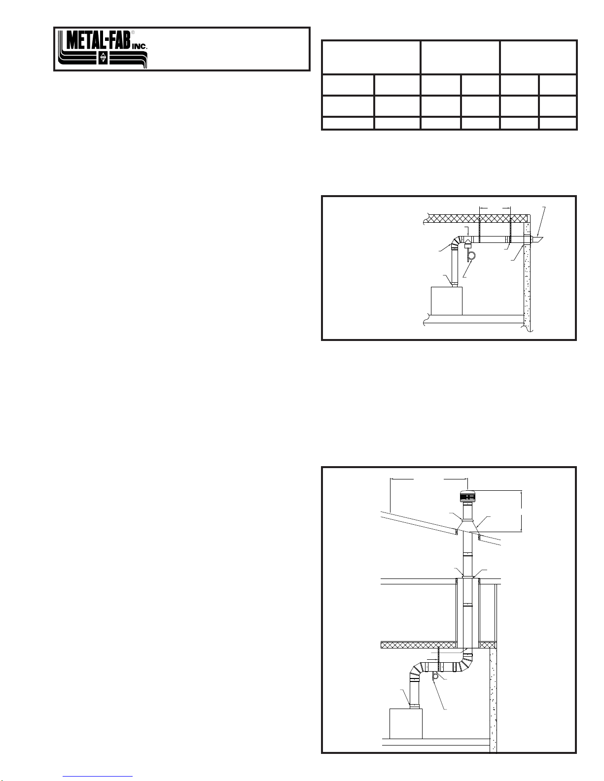
Examples of acceptable methods of installation which demonstrate minimum
clearances and supporting means are show below:
For venting systems that extend through any zone above that on which the
connected appliance is located (except for one and two family dwellings), the
vent system shall be enclosed with an enclosure having a re resistance rating
equal to or greater than that of the oor or roof assemblies through which it
passes.
When installed on Cat. II, III or IV appliances, Corr/Guard shall not be routed
into, through or within any other vent, existing masonry or factory built vent.
Exception: An abandoned masonry vent may be used to route the venting
system if no other appliance is vented into the same masonry vent and the
venting system is terminated beyond the terminus of the masonry vent.
To limit condensation and provide additional protection, it is recommended that
vents exterior to the structure and below the rooine be enclosed.
WALL
THIMBLE
TO DRAIN, DISPOSE OF
CONDENSATE ACCORDING
TO LOCAL CODE
7' MAX.
APPLIANCE
TERMINATION
APPLIANCE ADAPTER
SEAL AT APPLIANCE WITH
HIGH TEMPERATURE RTV
ELBOW
HORIZONTAL DRAIN TEE
OR DRAIN FITTING
HANGER
STRAP
FLASHING
3' MIN.
10'
SEE NOTE 2
APPLIANCE
APPLIANCE ADAPTOR
SEAL AT APPLIANCE WITH
HIGH TEMPERATURE RTV
TO DRAIN
DISPOSE OF
CONDENSATES
ACCORDING TO
LOCAL CODES
HORIZONTAL
DRAIN TEE OR
DRAIN FITTING
WITH TEE
HANGER STRAP
FIRESTOP
SUPPORT CLAMP FIRESTOP
STORM COLLAR
SEE NOTE 1
Note 1 - Apply caulking or
Metal-Fab MST Tape where vent
passes through storm collar.
Note 2 - 2’ minimum height
above any roof surface within 10’
horizontally.
Vertical
Installation
Side Wall
Installation

TABLE 2 - Support Limits and Framing Dimensions (Vertical)
Support Method Pipe
Size Maximum
Height Frame Dimensions
(Inside Dimensions)
Plate Supports,
Firestops & Roof
Supports
3” 30’ (9m) 7” x 7” (minimum)
4” 30’ (9m) 8” x 8” (minimum)
5” 30’ (9m) 9” x 9” (minimum)
Wall Supports
3” 30’ (9m)
Not Applicable4” 30’ (9m)
5” 30’ (9m)
JOINT ASSEMBLY
Connections between vent and ttings are male/female type. The inner duct is
sealed with an integral seal gasket and the joint is mechanically secured via the
overlapping outer wall of the double wall pipe.
NOTE: When assembling Corr/Guard double wall vent, always install the
female ue end elevated above the male ue end. The “UP” arrow will point to
the elevated female ue end. Change of directions are made by using male to
male or female to female adapter depending on the ow of the condensate.
Joints are assembled per the following steps:
1. Before assembly, observe
that the seal gasket is
located within the female
inner pipe joint. Locate
next pipe or tting with
male inner pipe joint and
inserttobeginengagement
of inner pipe joint.
2. As the joint further
engages, align the male
and female ends of the
outer wall of each pipe so
that they begin to engage
as the pipes are further
pushed together.
3. Pipe joint is fully engaged
when the female end of
the outer pipe comes in
contact (or is at least within
1/16th inch) to the base of
bead on the male end of
the adjoining vent pipe.
4. When possible look within
the pipe assembly to verify
that no sign of seal gasket
is showing. Complete the
joint assembly by securing
the joint using #8 x 1/2”
sheet metal screws (3 per
joint) at each pre-punched
hole on the female end of
each joint.
WARNING: Sheet metal screws are for outer wall only. Never use screws,
rivets or other fasteners to penetrate the inner pipe wall.
INSTALLATION
• Install roof penetrations
as shown in this gure,
maintaining
minimum
clearances for enclosed or
unenclosed spaces. (See
TABLE 1)
• A cap is attached to the top
section using three #8x1/2”
sheet metal screws.
• Stack height above the
rooine should not exceed
5’ (1.5 m) unless supported
by guy wires or rigid support
bracing.
C US
LISTED
©2015 Metal-Fab, Inc. Form No. L2154 - 06/16
9537
Support horizontal runs adequately to maintain proper slope. If the horizontal
section of the vent exceeds 7 feet in length, install hanger straps (plumber’s
tape, wall hangers, or other non-combustible material) every 7 feet to support
the connector from ceiling joists or other solid structures capable of supporting
the vent.
NOTE: Do not rivet or screw the straps to the vent or otherwise puncture
the vent wall. Wrap an extra loop of strap around the vent to hold it in
position.
Vents must not sag or dip providing areas for condensate to collect.
Vertical supports are to be used after each transition to vertical and/or after
every 30 feet of vertical vent. Vertical support is required after every offset
elbow to prevent vertical loading on offsets.
TABLE 3 - Support Limits and Framing Dimensions (Horizontal)
Support Method Pipe
Size
Distance
Between
Supports
Frame Dimensions
(Inside Dimensions)
Wall Penetration 3” 7’ (2.1m) 8” x 8” (minimum)
4” 7’ (2.1m) 9” x 9” (minimum)
5” 7’ (2.1m) 10” x 10” (minimum)
Horizontal Runs &
Between Elbows
3” 7’ (2.1m)
Not Applicable4” 7’ (2.1m)
5” 7’ (2.1m)
VARIABLE LENGTH
For installations that require non-standard vent lengths, Corr/Guard Variable
Length vent sections may be used. The vent section consists of a telescoping
inner conduit and outer casing. When installed, the VL vent section will add 5”
to 20” in nished length to the venting system.
To install the VL vent section, rst install the inner pipe section by connecting
the male section to the adjoining Double Wall vent pipe. Insert male section
until the bead of the joint stops at the edge of the female end of the Double
Wall vent section.
Next, expand the length of the inner pipe to the necessary length and tighten
the integral clamping band using a hex drive or screwdriver. Continue with the
next section of Double Wall vent, making sure to fully join the inner pipe of the
vent to the female end of the VL vent.
Once the vent system is completely assembled and supported, nish the VL
vent assembly by installing the outer casing wall around the VL inner pipe
section. Secure the casing by installing #8x1/2” sheet metal screws at pre-
punched hole locations.
NOTE: The VL pipe casing may be cut to length if needed.
MAINTENANCE
The Corr/Guard vent system should be inspected at least annually for the
presence of deposits or debris and any accumulation should be removed. The
vent system should also be inspected at regular periods for signs of leakage of
condensate or combustible products at any joint.
If the vent system incorporates a drain hose from either an inline tting or from a
drain tee, the hose must be inspected periodically to assure that water is in the
trap loop. If a proper trap loop in not maintained, exhaust from the connected
appliances may accumulate in the building area.
IMPORTANT: The listing for this product is void if components other than
those supplied as Listed Components by Metal-Fab, Inc. are used. All
warranties, stated or implied, are void if this product and the appliances to
which it is connected are not installed in accordance with their respective
instructions and local code requirements.
PITCHED
FLASHING
STORM COLLAR
RAINCAP
SEE CHART FOR
CLEARANCES
Roof Installation
SEAL
GASKET
1 2
43
1
16" GAP (MAX.)
Joint Assembly
This manual suits for next models
1
Other Metal Fab Fan manuals


Popular Fan manuals by other brands

BlueBuilt
BlueBuilt tv1210 extended manual

NOMA
NOMA Loen instruction manual

Monte Carlo Fan Company
Monte Carlo Fan Company 5HLR54 Series Owner's guide and installation manual

Thermador
Thermador RFPLT600P installation manual

Cornell
Cornell CCF-169CP user manual

Casablanca
Casablanca Metropolitan owner's manual


