Metal-Fach SE Operator's manual

Technical and operational documentation
SE
Original instructions, issue 08/2021
English

1
INTRODUCTION
Dear customer, thank you for purchasing METAL-FACH heating boiler. We hope that the operation of the device will meet your expectations and provide much satisfaction. The heating
boiler has been designed and manufactured in accordance with applicable norms and standards, which guarantee safe and reliable operation. Operation with strict observance of the recommendations
included in the manual attached to the device will ensure optimal and reliable operation of the central heating boiler for many years.
The product is not intended for use by persons with reduced physical / mental capabilities or lack of experience and knowledge, if these persons are supervised or instructed by a person responsible for
their safety. Operation by children is prohibited.

2
Table of Contents:
1. Introductory acts................................................................................................................3
2. Informative pictograms .....................................................................................................3
3. Symbols used in the manual.............................................................................................3
4. Definition of terms used in this manual ..........................................................................3
5. General information ..........................................................................................................4
6. Boiler equipment ...............................................................................................................4
7. Application ..........................................................................................................................4
8. Basic elements of boiler construction..............................................................................4
9. Basic dimensions of SE boilers .........................................................................................7
10. Technical data of SE boilers ..............................................................................................9
11. Fuel ....................................................................................................................................10
12. Requirements for the boiler house and boiler installation..........................................10
13. Boiler installation .............................................................................................................11
14. Boiler connection to the heating system.......................................................................12
15. Requirements for the expansion vessel ........................................................................14
16. Boiler connection to the electrical installation..............................................................14
17. Connection of boiler to chimney ....................................................................................14
18. Commissioning the boiler ...............................................................................................15
19. When using the boiler, remember .................................................................................15
20. Cleaning and maintenance of the boiler .......................................................................16
21. Instructions for disposal of the boiler at the end of its service life.............................16
22. Examples of equipment failure ......................................................................................16
Warranty conditions 19
Confirmation of inspection, warranty repair, service: 21
EC/EU Declaration of Conformity 23
Warranty card for steel boilers, central heating water boilers 25
Boiler complaint notification 27
Report on the first start-up of the boiler 29
Report on the first start-up of the boiler 31
Table of Tables:
Table 2.1 Pictograms 3
Table 6.1 Boiler accessories 4
Table 9.1 Boiler dimensions (mm) SE 60 - 350 8
Table 10.1 Technical data for boiler SE 60-350 9
Table 13.1 Flammability of building masses and materials 11
Table 14.1 Designations used in the diagrams 12
Table 14.2 Designations used in the diagrams 12
Table 14.3 Designations used in the diagrams 13
List of Figures:
Figure 1.1 Nameplate 3
Figure 8.1 Basic components of the SE 60 boilers 5
Figure 8.2 Basic components of the SE 75 boilers 5
Figure 8.3 Basic components of the SE 120 - 250 boilers 6
Figure 9.1 Dimensions of boiler SE 60-350 7
Figure 12.1 Minimum distances for positioning the boiler in the boiler room 11
Figure 14.1 Scheme of connection of the boiler to the heating system 12
Figure 14.2 Scheme of connection of the boiler to the heating system 12
Figure 14.3 Connecting the boiler to the heating system 13
Figure 14.4 Connecting the boiler to a heating system with laddomat and buffer. 13

3
1. Introductory acts
(USER)
Activities to be performed during the METAL-FACH boiler acceptance:
●Check carefully that the boiler has been delivered complete (Table6.1) and that it has not
been damaged in transit;
●Compare the rating plate mounted on the boiler casing on the left or right side with your
order (Figure1.1);
●carefully read this manual - it contains information necessary for correct boiler operation.
In the event of problems encountered, please contact the service department or METAL-FACH
authorized service center. These persons have appropriate training and access to original parts to
correctly perform the service and installation of METAL-FACH boilers, confirmed by a certificate
issued in the company's headquarters.
Figure 1.1 Nameplate
2. Informative pictograms
(USER)
Table 2.1 Pictograms
Symbol
Description
Symbol
Description
Years of warranty (exchanger)
Controller
Approved boiler steel
Fan
Water grate
Thrust limiter
Adjustment of the chimney
draught
Large loading chamber
3. Symbols used in the manual
(USER/INSTALLER)
NOTE!
Very important information, always read it if it is present.
TIP!
It is worth reading this information, it makes it easier to use.
4. Definition of terms used in this manual
(USER/INSTALLER)
Central heating boiler - a device for burning various types of solid fuels to heat the heat
carrier (usually water) circulating in the central heating cycle.
Draft limiter - a device whose task is to regulate temperature in solid fuel boilers. As the
temperature rises, the airflow to the furnace is limited, which slows down the burning of fuel. As
the temperature decreases, the air inflow increases, which makes it possible to ignite the fuel
again.
Chimney draught regulator - is used to stabilize and reduce excessive negative pressure in
chimney ducts.

4
5. General information
(USER)
The Operation and Technical Manual is one of the product parts, delivered together with the
purchased central heating boiler. The Operation and Maintenance Manual includes data
concerning the construction, assembly and method of operation of the SE 45-200 series boilers.
Careful reading of the Operation and Maintenance Manual ensures proper and safe operation of
our boiler.
NOTE!
The user is advised to observe all instructions regarding the device contained in this
Operation and Maintenance Manual, in the Warranty Terms and Conditions and in
generally applicable legal regulations.
The boilers are delivered assembled. They are set up and fixed to a pallet permanently.
Additional protection in the form of foil packaging is used.
When transporting the boiler, it should be secured against shifting or rotation on the truck's
loading bed with the use of protective equipment, e.g. belts. The transport of boilers should be
done in accordance with the rules concerning the transport of materials. Loading and unloading
should be done with the use of lifting devices (forklift) with a lifting capacity greater than 1000 kg.
6. Boiler equipment
(USER)
The scope of delivery includes both basic and additional elements, depending on the order.
During the acceptance of the product it is necessary to inspect it carefully to check if it was not
damaged during transport and check the completeness of the equipment. The elements included
in the basic and additional equipment are described below (Table6.1).
Table 6.1 Boiler equipment
Basic equipment:
Unit of
measuremen
t
Quantity
Central heating boiler
piece
1
Ash drawer
piece
1
Boiler cleaning tools:
●poker
●brush
piece
1
Thermometer
piece
1
Additional equipment:
Unit of
measuremen
t
Quantity
Thrust limiter
piece
1
Documentation:
Unit of
Quantity
measuremen
t
Technical and propulsory documentation of the boiler
piece
1
NOTE!
METAL-FACH company reserves the right to introduce without prior notice changes
in technical parameters, equipment and specifications of the offered goods.
7. Application
(USER/INSTALLER)
Steel water boilers are designed for heating usable water in central heating systems. They are
designed for heating residential buildings such as: single-family and multi-family houses, utility
buildings, public utility facilities. Thanks to the application of modern constructional solutions the SE 45-
200 boiler reaches efficiency of ≤81%. Correct operation and achieving the full capacity of the boiler
depend on the quality of the executed installation, appropriate chimney draught, correct operation and
maintenance of the boiler.
NOTE!
The boilers are designed to work in open and closed water systems with
gravitational or forced circulation, with safety devices in accordance with the
requirements of the current standard PN-B-02413 Heating and Heat Engineering
and a closed system in accordance with PN-EN 12828 Heating Installations in
Buildings. Design.
8. Basic elements of boiler construction
(USER/INSTALLER)
The water body is made as a welded structure from approved steel sheets 6 mm thick P265GH
(for elements in contact with exhaust gases) and 4 mm (for other elements) S235JR+N.
5
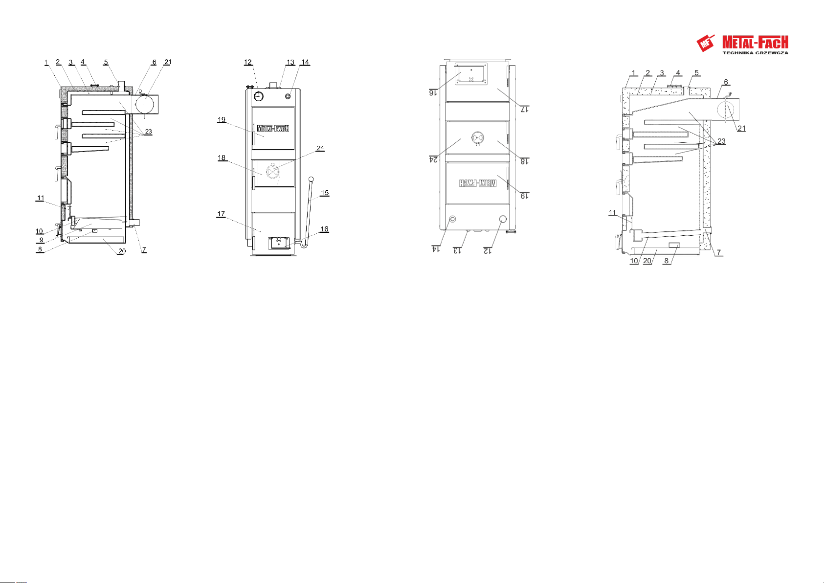
Figure 8.1 Basic components of the SE 60 boilers
Figure Description:
1. Boiler casing
2. Thermal insulation
3. Boiler body
4. Fan fixing
5. Supply spigot
6. Flue
7. Return spigot
8. Blow-up window
9. Movable grate
10. Water grate
11. Slatted doors
12. Thermometer
13. Temperature sensor sockets
14. Air distribution valve stub
15. Lever for the redrawing
16. Air dispenser
17. grate and ash door
18. Charging door
19. Clearance doors
20. Ash drawer
21. Exhaust gas throttle
22. -
23. Convection channels
24. Secondary air damper
Figure 8.2 Basic components of the SE 75 boilers
Figure Description:
1. Boiler casing
2. Thermal insulation
3. Boiler body
4. Fan fixing
5. Supply spigot
6. Flue
7. Return spigot
8. Blow-up window
9. -
10. Water grate
11. Slatted doors
12. Thermometer
13. Temperature sensor sockets
14. Flue converter stub
15. - –
16. Air dispenser
17. grate and ash door
18. Charging door
19. Clearance doors
20. Ash drawer
21. Exhaust gas throttle
22. - –
23. Convection channels

6
Figure 8.3 Basic components of the SE 120 - 250 boilers
Figure Description:
1. Boiler casing
2. Thermal insulation
3. Boiler body
4. Fan fixing
5. Supply spigot
6. Flue
7. Return spigot
8. -
9. -
10. Water grate
11. Slatted doors
12. Thermometer
13. Temperature sensor sockets
14. Flue converter stub
15. - –
16. Air dispenser
17. grate and ash door
18. Charging door
19. Clearance doors
20. -
21. Exhaust gas throttle
22. - –
23. Convection channels
7
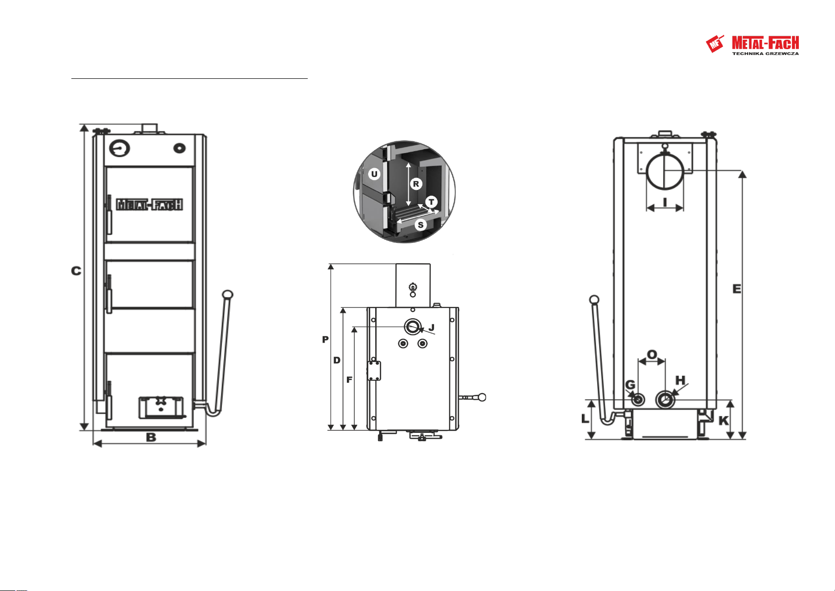
9. Basic dimensions of SE boilers
(USER/INSTALLER)
Figure 9.1 Dimensions of boiler SE 60-350
8
Table 9.1 Boiler dimensions (mm) SE 60 - 350
TYPE
SE 60
SE - 75
SE - 95
SE - 120
SE - 150
SE - 200
SE - 250
SE- 350
A
-
-
-
-
-
-
-
-
B
530
580
680
770
860
860
860
1202
C
1530
1530
1530
1830
1910
2110
2110
2030
D
800
800
800
1120
1170
1170
1270
1726
E
1330
1330
1330
1690
1780
1980
1980
1553
F
584
584
584
480
660
655
655
711
G
3/4"
3/4"
3/4"
3/4"
3/4"
3/4"
3/4"
1 ¼”
H
1,5"
1,5"
1,5''
2''
2''
2''
2''
101,6
I
200
200
200
250
250
250
250
350
J
1,5"
1,5"
1.5''
2''
2''
2''
2''
101,6
K
225
225
225
195
180
180
180
382
L
175
175
185
100
155
155
155
344
M
-
-
-
-
-
-
-
-
N
-
-
-
-
-
-
-
-
O
130
160
210
185
234
234
234
356
P
960
960
960
1550
1580
1580
1580
2230
R
550
550
550
650
700
900
900
1045
S
600
600
600
900
950
950
1050
990
T
340
390
490
540
640
640
640
984
U
340x200
390x200
490x250
540x300
640x300
640x300
640x300
624x468

9
10. Technical data of SE boilers
(USER/INSTALLER)
Table 10.1 Technical data for boiler SE 60-350
PARAMETERS
UNIT S.I.
BOILER MODEL
SE 60
SE - 75
SE - 95
SE - 120
SE - 150
SE - 200
SE - 250
SE- 350
Nominal heat output when burning hard coal
[kW].
60
75
95
120
150
200
250
350
Heating surface
[m2]
3,4
3,8
4,5
6,9
8,0
9,2
10
18,32
Area that can be heated
[m2]
600
600-750
750-950
950-1200
1200-1500
1500-2000
2000-2500
2500-3500
Water capacity
[L]
90
105
115
260
290
316
330
713
Maximum operating pressure
[bar].
1,5
1,5
1,5
1,5
1,5
1,5
1,5
1,5
Maximum operating temperature
[°C]
95
95
95
95
95
95
95
95
Test pressure
[bar].
4
4
4
4
4
4
4
4
Boiler class
[bar].
3
3
3
3
3
3
3
3
Boiler efficiency
[%]
≤81
≤81
≤81
≤81
≤81
≤81
≤81
≤81
Fuel
[-]
hard coal, wood
Design flow resistance ΔT
[10K]
2,36
3,14
4,20
7,45
11,65
16,76
26,20
-
Design flow resistance ΔT
[20K]
1,18
1,57
2,10
3,73
5,825
8,38
13,10
-
Boiler weight
[kg].
438
480
521
850
1015
1090
1160
2050

10
11. Fuel
(USER)
The fuel for SE series boilers is deciduous firewood with humidity not exceeding 20%, hard
coal of OI range.
It is recommended to use deciduous wood such as: beech, hornbeam, oak, birch, alder, ash.
The use of coniferous wood is not recommended, as it causes the boilers to smoke and requires
more frequent cleaning.
NOTE!
When using wood with moisture content of more than 20%, it is advisable to use
an acid resistant steel insert in the flue pipe.
12. Requirements for the boiler house
and boiler installation
(USER/INSTALLER)
In Poland, boiler houses built for solid fuel should meet the requirements of the following
standard
PN-87/B-02411 "Boiler houses built for solid fuel" and
Dz. U. 2015.0.1422 They are divided into two types:
1) For small boiler plants up to 25 kW capacity, the following requirements should be met:
●The boiler should be placed as centrally as possible in relation to the heated rooms and in
a separate room;
●The material of which the boiler room floor is made should be non-flammable, in case of
flammable material, the floor should be covered with 0,7 mm thick steel sheet at a
distance of at least 50 cm from the edge of the boiler; the boiler should be placed on a
foundation made of non-flammable materials, protruding 0,5 cm above the floor level and
edged with steel angles;
●there should be artificial lighting in the room, natural lighting is also advisable;
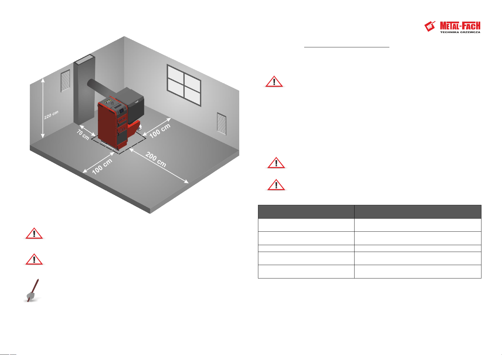
●the distance from the back of the boiler to the wall should not be less than 70 cm, from the
side of the boiler to the wall not less than 100 cm and from the front of the boiler to the
opposite wall not less than 200 cm;
●the height in new buildings should be at least 220 cm, in case of existing buildings the
boiler room height is at least 190 cm, with ensured proper ventilation (supply and
exhaust);
●Supply ventilation shall be by means of an unsealed opening having a minimum cross-
section of 200 cm2 and placed up to a maximum of 100 cm above floor level;
●exhaust ventilation should be carried out with an exhaust duct made of non-flammable
material, minimum cross-section 14 x 14 cm, with an inlet opening under the boiler room
ceiling; the exhaust duct should be led above the roof and located near a chimney; no
devices allowing to close it can be located on the exhaust duct
●the chimney section should not be smaller than 20 x 20 cm;
●there should be a floor drain in the floor of the boiler room;
●The optimal place for fuel storage is a separate room located near the boiler room;
●ash and slag must be collected in suitable containers for daily emptying.
2) Boiler houses with a heat output of 25 kW and over shall additionally meet the
following requirements:
●The distance between the boiler and the chimney furthest away from the chimney, for
gravity draught, must not exceed 50 cm of chimney height;
●Fuel storage and slag storage should be located next to the boiler hall at a storage height
of up to 220 cm with a minimum of 50 cm free space above the fuel;
●facilities and equipment shall be provided to enable the vertical and horizontal transport
of fuel and slag;
●fuel storage rooms shall be naturally unforced ventilated to permit one complete change
of air per hour in the fuel storage room and three complete changes of air in the slag
storage room;
●boiler house entrance door should be non-flammable (class 0,5 of fire resistance),
minimum width 80 cm, opening to the outside; it should have a handleless locking system
enabling opening to the outside under pressure, to the inside using the handle;
●requirements concerning ventilation are the same as for boiler houses of smaller capacity;
additionally, in boiler houses whose capacity exceeds 400 kW, in addition to supply and
exhaust ventilation, there should be mechanical ventilation, periodically activated when
pouring fuel and slagging the boilers, ensuring a minimum of 10 full air changes per hour;
●natural light should be provided in the boiler room, illuminating the boiler from its front,
and the window area should be minimum 1/15 of the boiler room floor area; half of the
installed
●shall be capable of being opened; electric lighting and an electrical socket, having a voltage
not exceeding 24 volts, shall also be provided in the room;
●there should be a drainage well in the floor to allow water cooling, and its capacity should
be equal to the water capacity of the largest boiler, but not more than 2 m3;
●in the boiler room, thermal conduits should be insulated;
●The boiler location with the minimum required distances is shown in the boiler room
diagram (Figure12.1).
NOTE!
Mechanical exhaust ventilation should not be used in the boiler room.
NOTE!
Ensuring a sufficient supply of fresh air into the boiler room will enable efficient
combustion of the fuel.
11
Figure 12.1 Minimum distances for placing the boiler in the boiler room
NOTE!
Excessive carbon dioxide in the room should be prevented.
NOTE!
More detailed information on the requirements for the construction of a boiler
house can be found in the Regulation of the Minister of Infrastructure
dated March 12, 2009.
TIP!
The aforementioned provisions are guidelines that should be reviewed as the
regulation is subject to revision.
13. Boiler installation
(USER/INSTALLER)
An important part of the installation is a correct positioning and leveling of the SE type boiler,
these boilers do not require special foundations. The boiler must stand vertically.
NOTE!
An improperly leveled boiler can be damaged.
The boiler must be placed on a heat-insulating, non-flammable pad that is 2 cm larger on each
side than the base of the boiler. If the boiler is located in a basement, it is recommended that it be
placed on a foundation of at least 5 cm. The strength of the foundation as well as the fire
protection conditions are key guidelines when placing the boiler in the right location, these
include:
●20 cm safety distance from flammable materials;
●40 cm for flammable materials of flammability grade C3;
●40 cm if flammability is not known.
NOTE!
The return water temperature from the system to the central heating boiler should
not be lower than 45ºC.
NOTE!
It is required to connect the boiler to the heating system using a four-way valve.
Table 13.1 Flammability of building masses and materials
Flammability of building masses and
products
Building materials and products
A - Non-flammable
Sandstone, concrete, bricks, fire plaster, mortar,
ceramic tiles, granite
B - Hard to burn
Wood and cement boards, fibreglass, mineral
insulation
C1 - Hard to burn
Beech wood, oak wood, plywood
C2 - Medium flame
Pine, larch and spruce cork, sawn timber planks,
rubber floor coverings
C3 - Readily combustible
Asphalt plywood, celluloid, polyurethane, polystyrene,
polyethylene, plastic, PVC
12
14. Boiler connection to the heating
system
(INSTALLER)
Boiler connection to the central heating system should be performed by a firm authorized by
the manufacturer, and the fact of proper connection should be confirmed on a warranty card
attached to this manual. Boiler should be connected according to producer recommendations, in
accordance with this manual.
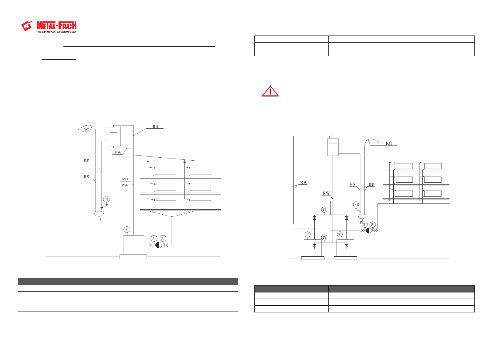
Boiler connection diagrams to the heating system in accordance with the PN - 91/B - 02420
standard.
Figure 14.1 Scheme of connection of the boiler to the heating system
Table 14.1 Designations used in the diagrams
Designation
Description
RO
Vent pipe
RW
Collector pipe
RS
Signal tube
RP
Overflow pipe
RB
Safety pipe
T1
Temperature
P1
Pressure
NOTE!
It is recommended to perform the first start-up of the boiler in accordance with
the guidelines included in the Operation and Technical Documentation, by a person
holding a valid license (information about persons authorised to start up the boiler
is available from the Producer - phone: +48 85 711 94 56).
Figure 14.2 Scheme of connection of the boiler to the heating system
Table 14.2 Designations used in the diagrams
Designation
Description
T
Temperature sensor
Tk
Boiler temperature sensor
Tz
Outdoor temperature sensor

13
Tcw
Domestic hot water temperature sensor
Tco
Central heating temperature sensor
Tpw
Boiler return temperature sensor
Tpod
Feeder temperature sensor
Figure 14.3 Connecting the boiler to the heating system
Table 14.3 Designations used in the diagrams
Designation
Description
T
Temperature sensor
Tk
Boiler temperature sensor
Tz
Outdoor temperature sensor
Tcw
Domestic hot water temperature sensor
Tco
Central heating temperature sensor
Tpw
Boiler return temperature sensor
Tpod
Feeder temperature sensor
Figure 14.4 Connecting the boiler to a heating system with laddomat and buffer.
Figure Description:
1. Outside the building
2. Expansion vessel
3. Room controller
4. Mixer
5. Heater
6. Heating circuit
7. Central heating pump
8. Central heating water (DHW) pump
9. Buffer
10. Laddomat
14
15. Requirements for the expansion
vessel
(INSTALLER)
Every open heating system should be equipped with a collecting vessel whose task is to absorb
the increase in the volume of water filling the system and to vent it. The vessel should be installed
in the highest point of the system, if possible in a vertical line above the boiler(s).
The volume of the collection vessel can be estimated by taking the unit volume in relation to
one kW of thermal capacity is 1-2 dm3.
The vessel is equipped with a ferrule for the connection of a tolerable safety pipe, a
precipitation safety pipe and an overflow pipe with associated vent.
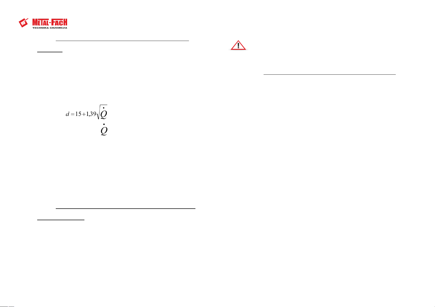
The diameter of the vent pipe and the overflow pipe shall be at least:
[MM]
- boiler output [kW].
The most important requirements for safety devices are as follows:
●the vessel should have a volume of approximately 3.5% of the volume of water contained
in the heating system including the boiler;
●Every boiler should absolutely have a safety pipe and an overflow pipe;
●The system should be equipped with a signalling and collecting pipe and a venting stub for
the collecting vessel.
If several boilers are set up, each of them should be equipped with a safety pipe according to
the given rules in PN-91/B02413 - protection of open-system water heating installations. No shut-
off valves can be installed on safety and overflow pipes, and the pipes and vessel should be
protected against freezing.
16. Boiler connection to the electrical
installation
(INSTALLER)
The boiler is designed for connection to 230V/50Hz. Installation should be made by a qualified
person. The socket outlet 230V/10A with earthing should be easily accessible. Boiler power supply
and boiler room lighting should have a different circuit.
Completion of the installation and the heating test must be recorded in the Warranty Card. The
completed Warranty Card should be sent to the manufacturer's address by the user in order to
register the user in the company's system.
NOTE!
The first start-up of the boiler must be carried out only by a service technician
trained by the manufacturer, with a valid certificate of METAL-FACH Authorized
Service Provider, METAL-FACH Distributor or a person holding the SEP license up
to 1.5 kW.
17. Connection of boiler to chimney
(INSTALLER)
Smoke ducts
The purpose of flue pipes is to reliably carry exhaust fumes to the outside and to draw in air
for fuel combustion. The chimney draught required for this depends on:
●Temperature difference between hot exhaust gas and cold air;
●effective chimney height;
●chimney section not less than 20 x 20 cm;
●the execution of the chimney (as smooth internal surfaces as possible) and the tightness of
the joints;
The effective height of the chimney is the difference in height between the highest hearth and
the exit of the chimney. The effective height of individual chimneys must be at least 4 m and
common chimneys for solid and liquid fuels at least 5 m. The difference in height between two
fireplaces must not be greater than 6.5 m.
In the case of sloping roofs, chimneys should end at the ridge (the highest point of the roof), in
the area of free wind flow. This avoids draught disturbance. Always pay attention to the position of
the building in relation to other buildings.
Chimney selection
In most cases an approximate method or selection according to chimney manufacturer's
chimney diagrams is sufficient for selecting the chimney. in special cases (unfavourable pressure
and temperature relationships, large flue gas volume) chimneys are calculated according to PN-EN
13384-1+A2:2008 standard.
Chimneys for solid fuel boilers
Please note that solid fuel stoves with a nominal heat output >20 kW and without a fan need
their own chimney. For solid fuel stoves, single-layer brick chimneys can be used. Nowadays three-
layer chimneys with smooth surfaces and good thermal insulation are used.
Flue
The boiler is connected to the chimney by a flue pipe and a flue duct. Smoke ducts are pipes
and fittings that are laid indoors. Smoke ducts meet fire safety requirements concerning chimneys
and are often made of the same material as the main chimney. Smoke ducts should be made of
non-combustible products. Smoke ducts or casing should meet the requirements specified in the
Polish Standard concerning fire testing of small chimneys. A 12 cm thick solid brick housing, built
on cement-lime mortar with external plaster or pointing, is acceptable. Joints should be as short as
possible and laid with an elevation to the chimney to avoid heat loss and additional resistance.
They shall not be routed to other floors. Flue pipes should not be laid in rooms where fireplaces
cannot be fitted, nor should they be placed in walls or ceilings. In order to protect the chimney
15
against dampness and draught limitation, acid resistant or ceramic chimney liners should be used,
with condensate draining to the sewage grid. A distance of at least 6 m should be kept between
the chimney and the nearest edge of a tree crown.
18. Commissioning the boiler
(USER/INSTALLER)
Before you start a fire in the boiler, check if the central heating system has been properly
made and if it is properly filled with water - up to the overflow pipe from the vessel.
For filling the entire system or for making up for losses, softened/chemically treated water,
distilled water or rainwater would be most suitable.
In addition, check that the grate is cleaned of any unburnt fuel, ash and slag from the previous
firing and that the ash has been removed from the ash pan.
Recommended firing-up (correct firing from the top) - fill the prepared grate deck with fuel
(when burning wood - full load - to the bottom edge of the inlet, put logs across the boiler) Place a
kindling layer (paper, wood pieces) on the surface and set the fire. The boiler should be started up
with the primary air dosing flap in the lower door (grate and ash door) open, and with the
secondary air throttle in the charging door.
Boiler operation in the upper combustion system takes place in a system with cyclical fuel
filling, which means that after complete burning out of the fuel portion poured into the
combustion chamber and removing ash, the chamber is filled again and a new fuel portion is
ignited with the use of kindling fuel.
We do not recommend firing up the fuel "from below" in top-firing type boilers.
Before lighting the kindling layer, make sure that the chimney provides sufficient draught.
Insufficient draught is most often encountered when the boiler is started up for the first time or
after a longer break in operation, when the boiler and the chimney have cooled down.
To check the chimney draught, place a lit piece of wood close to the air inlet duct with the
damper open.
If you find that the flame is not being drawn intensively into the boiler, this indicates
insufficient chimney draught.
In this case, before setting the layer on fire, the chimney must be "warmed up" by proceeding
as follows:
●Put a few sticks of wood in the flue pipe and set it on fire;
●Keep the fire going until the chimney draught increases (the flame is drawn up the
chimney);
●After the wood has burnt out, scoop the unburnt residue and dispose of it in the ash pan.
When the boiler reaches the required water temperature, it is necessary to adjust the
combustion intensity. The combustion intensity is adjusted by a proper setting of the adjustment
screw of the primary air dosing flap and by a proper adjustment of the secondary air throttle.
During normal boiler operation it is necessary to periodically check and replenish the fuel as
specified above. In the case of hard coal, strike the hook to cause the fuel to fall down.
When opening the fuel door, be very careful, because if the door is opened abruptly, explosive
gases (degasification products) can be ignited. When opening the fuel door, stand at the side of
the boiler, slightly open the door, wait for a moment until the combustion gases are discharged
from the fuel tank into the chimney and then slowly open it. Do not stand in front of the door
opening. A similar procedure should be followed when opening the other doors during boiler
operation.
NOTE!
If for any reason there is a lack of water in the boiler - mains system, do not
top up with cold water. Cool the boiler down to the temperature of 30°C as soon
as possible and only after the boiler has cooled down, add water and start
burning again.
NOTE!
The flow of cold water on the boiler walls when the boiler is hot can cause
an explosion of the boiler and consequently damage the heating equipment. In
extreme cases, it can cause damage to buildings and injuries to people.
NOTE!
When opening the door do not stand in front of the boiler, it can cause burns.
When starting up the boiler cold or for the first time, a phenomenon of "sweating of the boiler"
can occur. This gives an impression of leakage. In this case, it is necessary to carry out an intensive
burning process (70-80ºC) to dry and warm up the boiler and the flue for even 2-3 days.
To increase the service life of the boiler it is recommended to keep the flue gas temperature
180ºC above the ambient temperature, and the boiler water temperature should not be lower
than 60ºC.
Maintaining a suitably low radiator temperature in this situation during autumn or spring can
be achieved by, among other things:
Correct boiler selection according to the size of heated rooms;
Use of three-way or four-way mixing valves between the water supply and return, manually or
automatically controlled.
Inadequate insulation of the expansion (overflow) vessel can also cause a boiler explosion with
all its negative consequences.
Frozen water in the expansion vessel breaks the connection between the central heating
system and the boiler and the atmosphere, and when the temperature of the boiler water rises,
the pressure in the system increases uncontrollably, which may result in a boiler explosion.
19. When using the boiler, remember
(USER)
●The boiler may only be operated by adults who have read the operating manual;
●It is forbidden for children to be near the boiler without the presence of adults;
●If flammable gases or vapours get into the boiler room or during the work, in which there
is an increased risk of fire or explosion (gluing, painting, etc.), the boiler must be switched
off before such work is started;
16
●When cleaning carbon in the retort, trough, the boiler should be turned off ("OFF"
position);
●When adding fuel to the tank, turn the boiler off ("OFF" position);
●Do not use flammable liquids for firing up the boiler, the boiler should ignite automatically
(by means of an igniter);
●When cleaning the boiler, turn the appliance off ("OFF" position);
●The boiler must not overheat in any way during operation;
●Do not place flammable objects on the boiler or in its close vicinity;
●When removing the ashes, flammable materials must not be located within 150 cm of the
boiler;
●The ashes should be put into heatproof dishes with a lid;
●When the boiler is operated at a temperature lower than 60°C, the steel exchanger may
dampen and cause corrosion due to low temperature, which shortens the exchanger's life;
therefore the temperature during boiler operation must be at least 60°C;
●After the end of the heating season the boiler and the flue pipe must be thoroughly
cleaned;
●The boiler room should be kept clean and dry.
NOTE!
The product is not intended for use by persons with reduced physical / mental
capabilities or lack of experience and knowledge, unless they are supervised or
instructed by a person responsible for their safety.
NOTE!
Any unauthorised interference with the electronics or the design of the boiler is
prohibited.
20. Cleaning and maintenance of the
boiler
(USER)
NOTE!
The boiler may only be cleaned when the appliance is switched off from the mains.
To save fuel it is necessary to keep clean the combustion chamber and convection ducts of the
boiler. It is necessary to clean walls and grates in the combustion chamber through the charging
and furnace doors. Boiler exchanger and ash collector must be also cleaned regularly.
The convection ducts (ducts) and the flue pipe must be cleaned through a cleanout on the
boiler flue and at the bottom on the side wall. Cleaning should be done with wire brushes on
extension tubes. The above actions must be performed during periodic boiler standstill, preferably
every 100 hours of boiler operation. Thorough cleaning of the boiler should be done once a
month.
In the case of combustion of poorer grades of fuel, these operations should be carried out
more frequently.
21. Instructions for disposal of the
boiler at the end of its service life
(USER)
Before scrapping the boiler, all electronic components must be disconnected from the boiler.
They must be disposed of in accordance with the European Directive 2002/96/EC on the disposal
of electronic and electrical equipment. For correct disposal, contact the manufacturer of the
electronic components according to the above mentioned European Directive.
Steel elements from which the boiler is made should be scrapped in designated places (scrap
metal purchase).
NOTE!
Do not dispose of the old boiler, intended for scrapping, or its components with
general waste.
22. Examples of equipment failure
(USER)
Before you call for service, read the frequently asked questions.
NOTE!
In case of an unjustified service call, the customer covers the costs of labour and
travel (price list is available at www.metalfachtg.com.pl).
You can report the problem online at our website: www.metalfachtg.com.pl/zglos-problem-
online.
HOTLINE: +48 85 711 94 54 ext.17

17
Question
Reply
Explanation
Smoke escapes from the
hopper or ash door
- no thrust;
- improper connection of the boiler to the chimney;
- fuel residue has got under the hinge or seal; second stove
fitted in the same flue pipe;
- too small chimney section.
- seal the entrance of the flue pipe to the flue pipe;
- check the patency of the chimney and its parameters;
- check the sealant sealing the door;
- seal the stove outlet to the flue pipe to prevent cold air being sucked in;
- enlarge the chimney opening.
During the first start-ups
water escapes from the boiler
(leakage).
- condensation (boiler sweating).
- We fire up the boiler to the temperature above 80OC and maintain it for at least 6 hours.
If necessary, repeat this operation.
Boiler temperature too low.
- improperly selected boiler power (size);
- calorific value of the fuel too low;
- incorrect boiler regulation.
- See the section on boiler operation and maintenance;
- improperly selected boiler power.
A sudden increase in
temperature and pressure in
the boiler.
- no seal of the ash chamber;
-too large a chimney section.
- ensure the tightness of the door and the cleanout openings, if any;
- reduce the chimney cross section, install a sunroof.
18
Water leakage from
convection channels.
- bad fuel;
- combustion temperature too low;
- no air supply through air dampers;
- exhaust damper closed.
- use fuel of appropriate calorific value and moisture content;
- open the air dampers;
- open the flue gas dampers.

19
Warranty conditions
(USER)
User Statement:
I hereby declare that the boiler (hereinafter also referred to as "appliance") was delivered to
me as ordered, new and complete. The Vendor has familiarised me with the operation of the
appliance and provided me with a set of documentation (in particular: Technical and Operating
Documentation including, but not limited to, instructions for installation and operation of the
device, warranty conditions). I acknowledge the manufacturer's recommendation to subject the
device to regular annual technical inspections, which should be confirmed in the warranty card.
…………………………………………………………….
Date and legible signature of the User
Warranty coverage:
1. Liability under the warranty covers only defects resulting from causes inherent in the
device at the time of its delivery to the user.
2. Warranty for the device is provided by the manufacturer (also referred to as the
"Guarantor"): Jacek Kucharewicz running the business activity under the name Metal Fach
Jacek Kucharewicz, 16-100 Sokółka, 66 Sikorskiego Street, Tax Identification Number (NIP):
545-100-10-62, Business Identification Number (REGON) 050073833, phone: +48 85 711
94 56).
3. Under the guarantee, the user shall be entitled to free-of-charge repair of the device, if
the defects of the device become apparent during the guarantee period. If the Guarantor
finds it impossible to repair the device or its part, the Guarantor reserves the right to
replace the device or its part with a new one.
Warranty Period:
For the device (boiler) - 2 years from the date of sale, but no longer than 36 months from the
date of manufacture, with the exception of:
a) exchanger - warranty is 5 years from the date of sale;
b) moving elements, cast iron, mechanical, worm - for which warranty is 1 year from the
date of sale;
c) operating elements (e.g. sealing cord, gaskets, verniculite, chamotte), electrical elements,
screw securing the screw coupling, pins - which are not subject to warranty.
Conditions for exercising the guarantee:
1. Installation of the appliance in accordance with the Technical and Operating
Documentation (in particular, connection of the boiler to a correctly installed system,
performing the first start-up in accordance with the guidelines of the appliance
manufacturer, use of devices protecting the boiler against cold water return (four-way
valve with a servo-motor, ice machine, etc.)
2. Sending to the Manufacturer's address a copy of a properly completed warranty card,
signed and stamped by the vendor within 30 days from the date of sale of the device
3. Presentation of properly filled warranty card (signed and stamped by the vendor) at the
time of claim and substantiation of the circumstances of purchase of the device (e.g.
receipt, invoice). In case of loss of the warranty card by the User, a duplicate will not be
issued.
4. User adherence to the recommendations contained in the Technical and Operating
Documentation of the device.
5. Perform the first start-up of the boiler, within 6 months from the date of installation of
the device by an installer, in accordance with the guidelines included in the technical and
operating documentation, by a person holding a valid license (information on persons
authorized to start up the boiler is available from the Guarantor - +48 85 711 94 56),
confirm this fact on the warranty card and send the start-up report to the Guarantor. The
first start-up of the boiler is a chargeable service and its cost is covered by the User.
6. Perform annual inspections of the device, in accordance with the guidelines contained in
the Technical and Operating Documentation, by specialist companies with appropriate
authorisations (a sample list of specialist companies is available from the Manufacturer -
under +48 85 711 94 56 and record their performance in the warranty card. Inspection of
the device is a chargeable service.
7. Servicing of the appliance (e.g. adjustment of the appliance, cleaning, measurements,
analyses of flue gases) should be performed by specialised companies with appropriate
authorisation (a sample list of specialised companies is available from the Manufacturer -
at +48 85 711 94 56), in accordance with the guidelines included in the Technical and
Operating Documentation, and the service should be recorded in the guarantee card. The
User may report the need for service interventions to the Manufacturer (infoline +48 85
711 94 56, www.metalfachtg.pl/zglos-problem-online). The service is chargeable.
8. Warranty repairs should be carried out only by specialised companies with appropriate
authorisation (a list of specialised companies is available from the Guarantor - phone +48
85 711 94 56) and recorded in the warranty card.
9. Use of spare parts and consumables that meet the parameters specified by the
manufacturer. It is recommended to use original parts.
10. The warranty covers the territory of the Republic of Poland.
Table of contents
Other Metal-Fach Tiller manuals


