Metal-Fach KRUK U-740 User manual
METAL-FACH Sp. z o.o.
16-100 Sokółka, ul. Kresowa 62
Tel (0-85) 711 98 40
Fax (0-85) 711 90 65
OPERATING INSTRUCTIONS
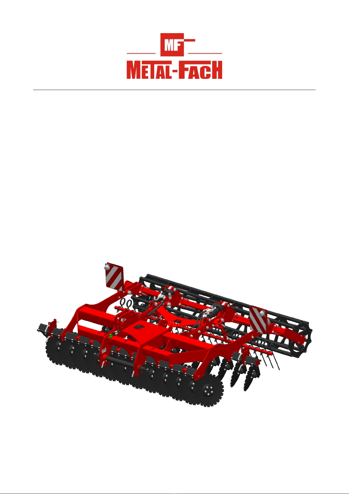
"KRUK" CULTIVATOR
Type U-740
Edition no. 03
Year of issue 2012
Original Operating Instructions
1

CE DECLARATION OF CONFORMITY
FOR THE MACHINE
Manufacturer:
METAL-FACH Sp. z o.o.
ul. resowa 62
16-100 SO ÓŁ A,
Machine:
" RU " Cultivator
type/model: U7400................................
serial number:........................................
year of manufacture:.............................
Function/ intended use: soil cultivation before sowing
We declare that the machine which this declaration concerns meets the
following requirements:
- Directive 2006/42/EC OF THE EUROPEAN PARLIAMENT AND OF THE COUNCIL dated
May 17th 200 on machines and the Resolution of the Minister of Economy of October 21st 2008
concerning general requirements for machinery (Journal of Laws, issue 199 item 1228);
Compliance has been evaluated with the following harmonised standards:
PN-EN ISO 4254-1:2009 + AC:2010
PN-EN ISO 13857:2010
PN-EN ISO 12100:2011
- and the following standards: PN-ISO 3 00:1998, PN-ISO 11 84:1998; and the Resolution of the
Ministry of Infrastructure of 31.12.2002 on the technical requirements for vehicles and the scope of
their necessary equipment (Journal of Laws 2003, issue 32 item 2 2 as amended).
Safety Test Report No. MF/1/2012
Person authorised to prepare the technical documentation: Metal-Fach Technical Department
This Declaration of Conformity becomes void and null if the machine's design is
changed or modified in any manner without prior consent from the manufacturer.
Sokółka .........................................
President of the Management Board
Jacek Marek Kucharewicz
2
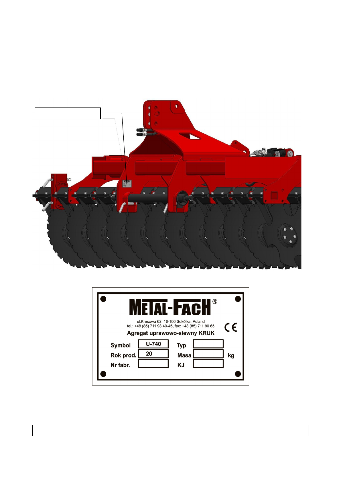
Nameplate
Please state the type and identification number of the machine in all communications,
questions and warranty issues.
The identification data of the machine can be found on the nameplate located on the left wall of the
frame near the lower strings beam of the three point hitch.
The manual is a part of the machine's base equipment.
3
NAMEPLATE

Identi ication data
Machine type cultivator
Commercial designation KRUK
Type / Code U-740..............................................
Serial no. .....................................................................................
Machine manufacturer "METAL-FACH" Sp. z o.o.
16-100 Sokółka
ul. Kresowa 62
Tel (0-85) 711 98 40
Fax (0-85) 711 90 65
Seller .....................................................................................
Address
.....................................................................................
Tel./Fax
.....................................................................................
Date of delivery .....................................................................................
Owner / User Name .....................................................................................
Address
.....................................................................................
Tel./Fax
HINT: Note down the type and serial number o your machine. Please give this number
every time you contact your supplier.
4

Table o contents:
page
CE DECLARATION OF CONFORMITY
NAMEPLATE
IDENTIFICATION DATA
1. INTRODUCTION................................................................................................................................6
2. INTENDED USE..................................................................................................................................6
2.1 OPERATION ACCORDING TO THE INTENDED USE
3. USER SAFETY.....................................................................................................................................7
3.1 GENERAL SAFETY REGULATIONS
3.2 MAINTENANCE AND SERVICING
3.3 TRAVELLING ON PUBLIC ROADS
3.4 SAFETY SIGNS
4. DISMANTLING AND DISPOSAL...................................................................................................11
5. LIGHT SIGNALS (OPTIONAL)......................................................................................................11
6. MACHINE DESIGN..........................................................................................................................12
6.1 TECHNICAL CHARACTERISTICS OF THE KRUK U-710 AND U-710/1 CULTIVATORS
7. DELIVERY AND LOADING ON MEANS OF TRANSPORT......................................................13
8. OPERATION AND USE....................................................................................................................13
8.1 PREPARATION OF THE MACHINE
8.2 COUPLING THE MACHINE TO THE TRACTOR
8.3 MACHINE ADJUSTMENT
8.3.1 ADJUSTMENT OF THE HARROW DISKS' WORKING DEPTH
8.3.2 WORKING DEPTH AND TINE ANGLE ADJUSTMENT
8.4 OPERATION OF THE MACHINE
8.5 LUBRICATION AND STORAGE
9. RESIDUAL RISKS............................................................................................................................16
9.1 DESCRIPTION OF RESIDUAL RISKS
9.2 EVALUATION OF THE RESIDUAL RISK
10. WARRANTY CONDITIONS AND WARRANTY SERVICES.....................................................17
WARRANTY CARD
COMPLAINT CALL
SERVICE LOG
11. LOCATION OF THE MACHINE'S CENTRE OF GRAVITY.....................................................17
12. STABILITY OF THE UNIT CONSISTING OF THE TRACTOR AND CULTIVATOR...........17
13. PARTS CATALOGUE......................................................................................................................22
13.1 USING THE PARTS CATALOGUE
13.2 ORDERING PARTS
5

1. INTRODUCTION
The following instruction manual describes the use and operation of the U-740 machine. If
particular problems arise during the operation of the machine which were not discussed in detail in
the operating instructions the customer may request supplementary information from the
manufacturer or the supplier. The crucial obligations of the manufacturer are stated in the warranty
document which specifies the complete and current regulations for warranty services.
META-FACH Sp. z o.o. reserves the right to introduce changes without prior notice and
without assuming any obligations resulting rom those changes.
The design of the machine allows for safe operation on condition that it is are used
according to the operating instructions. Therefore before starting the machine we request that the
users read the following manual and familiarise themselves with the safe operation conditions.
All operator of this machine must familiarise themselves with the contents of the operating
instructions before commencing works.
This is to make sure the user knows how to operate the machine properly and safely.
This also conditions that your warranty rights are maintained.
The manual is part o the machine's equipment.
2. INTENDED USE
The compact KRUK disc harrow is a universal tool for the cultivation of the top layer of soil
to the depth of 5 cm to 15 cm. It is designed for use after harvest and before sowing following
ploughing or in soil cultivation without ploughing, when the vegetation remains are not covered but
mixed with the top soil layer (i.e. mulched). It may be used on all types of soils including those with
stones thanks to the use of elastic suspension of the harrow discs. The harrow allows for opening
and mixing of the soil and in connection with the packer also for packing and compressing of soil.
Due to the resistance to clogging the harrow is well suited for the cultivation of tall stubbles which
remain after the harvest of crops and corn and for cultivation of aftercrops intended to be used as
fertiliser.
2.1 OPERATION ACCORDING TO THE INTENDED USE
The machine may be started, operated and repaired only be persons who are familiarised
with its operation and the operation of the tractor as well as with the rules of safe use of the
machine.
The manufacturer does not assume responsibility for any changes made by the user without
permission. During the service life of the machine only original parts manufactured by METAL-
FACH may be used.
6

REMEMBER - The machine is designed to be used only in agricultural applications. Any
use o this machine other than speci ied in section 2 is considered improper use. Improper
use also includes using the machine in work conditions other than those speci ied by the
manu acturer, improper repair and maintenance.
The manu acturer does not assume any responsibility or any damage resulting rom
improper use o the machine.
3. USER SAFETY
REMEMBER - Be ore starting the maintenance or use o the machine the user should
amiliarise himsel with these operating instructions and know the design o individual
assemblies and their unctions, scopes and means o adjustment paying particular attention
to the in ormation regarding sa e operation.
It is too late to learn that during work.
3.1 GENERAL SAFETY REGULATIONS
The safety regulations given below apply to the machine. Regardless of those regulations the
user must also follow the general safety and accident prevention regulations and the traffic code.
The machine (cultivator + tractor) should be operated maintaining all rules of safe operation,
in particular
•every time before start-up check the machine and the tractor - whether they are in condition
which guarantees safety during movement and operation;
•to maintain steerability the machine may only be coupled to a tractor with a full set of
weights on the front axle. When the machine is coupled the load on the tractor's front axle
must be at least 20% of the tractor's own weight;
•the user must make sure to follow the maximum allowable axle loads and transport
dimensions;
•when coupling the machine to the tractor, raising and lowering the machine using the
tractor's hydraulic system, unfolding the machine to its transport or working position and on
headlands the operator must ensure that there are no bystanders nearby, especially children;
•when the engine is running no person is allowed between the tractor and the machine;
•noise - the equivalent sound pressure emission corrected by A characteristics (LpA) does not
exceed 70 dB;
•when connecting the hydraulic lines to the tractor's hydraulic system the operator must make
sure that the system is not under pressure. The operator must check the positions of the
tractor hydraulic system control levers;
•it is only allowed to operate the hydraulic elements when no person is nearby;
•the hoses and pipes in the hydraulic lines must be checked on a regular basis and replaced
with new ones it they are damaged;
•all hydraulic lines must be replaced every 6 years;
•raising, lowering, folding and unfolding and movements of the machine should be done
slowly without jerking movements;
•it is forbidden to reverse the tractor and make turns when the machine is lowered to its
working position;
•when making turns bear in mind that there are protruding elements in the machine, the use
of tractor's independent brakes must be avoided;
•the user must check the tyre pressure in the tractor and in the machine;
•during transport no person should be allowed to stand on the machine nor any load may be
placed on it;
•any repairs, lubrication or cleaning of the working elements required during work may only
be performed with the engine turned off and the machine lowered;
7

•only uncouple the machine when its discs rest on stable firm ground, the hook support is
unfolded and the engine is turned off;
•the machine may only be stored in its unfolded position, resting on all working components;
•when not in use the machine should be stored in places where it cannot be accessed by
unauthorised persons and animals;
3.2 MAINTENANCE AND SERVICING
The technical maintenance may be performed when the machine is lowered to the ground. If
the machine is coupled with a tractor it must be turned off and the brakes must be engaged.
Only use tools and instruments that are in good condition and original materials and spare
parts.
Use standard pins and safety devices to lock the machine's bolts in place. It is forbidden to
use make-shift safety devices such as bolts, rods, wires etc. which may be the cause of damage to
the tractor or the machine during operation and may reduce safety.
3.3 TRAVELLING ON PUBLIC ROADS
According to the road travel safety rules /Regulation by the Minister of Infrastructure of
31.12.2002 Journal of Laws no. 32 of 2002, item 262/
A unit consisting o a tractor with a coupled arming machine must meet the
same requirements as an individual tractor.
WARNING - The machine (part o the unit consisting o the tractor and machine) is a part
protruding outside the outline o the vehicle and obstructing the tractor's rear lights and as
such it poses a threat to other vehicles travelling on the road.
REMEMBER - It is orbidden to travel on the roads with the unit (tractor + machine)
without appropriate marking.
While travelling on public roads with a unit consisting o the tractor and the machine
all rules o the Tra ic Code speci ic to vehicles o this type apply, in particular:
•the side sections of the machine must be folded to the transport position and secured with
bolts against unfolding during transport (see. fig. 1).
•during transport on the road the cultivators coupled to a tractor require
– marking with warning plates with red and white stripes,
– lights
– elements protruding to the side of the tractor (front marker lights - white),
– repeated rear lights of the tractor (combined lights + reflective lights),
– marking with a triangle plate indicating a slow moving vehicle,
•do not exceed the maximum allowable transport speed, which is
–on paved roads – up to 20 km/h,
–on dirt roads or cobblestone – 6 - 10 km/h
–on uneven roads – 5 km/h maximum
8

The speed must be adapted to road conditions and the condition of the road surface.
•special care must be taken while passing or overtaking other vehicles and on corners. The
maximum permissible width of the machine which is allowed on a public road is 3.0 m.
Fig. 1 Working and travelling positions of the machine (side sections folded).
9
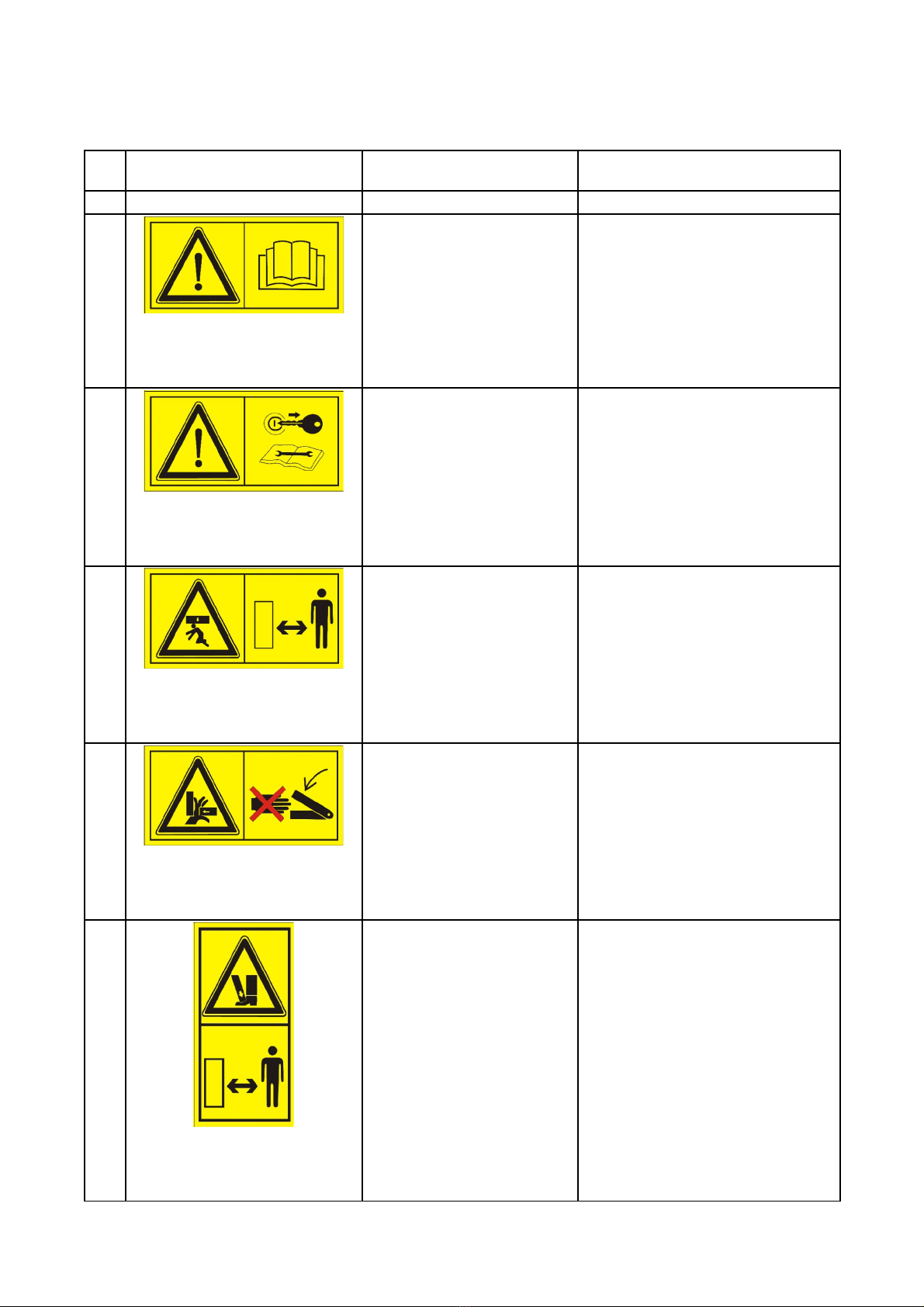
3.4 SAFETY SIGNS
Table 1
Item Safety Symbol
Meaning of the symbol (sign) or
text Location on the machine
1 2 3 4
1
1 pc.
Dimensions 100x50
Colour yellow background, black
figures
Read the operating instructions. On the front left section of the frame.
2
1 pc.
Dimensions 100x50
Colour yellow background, black
figures
Turn off the engine and remove
the ignition key before servicing
or repairs.
On the front left section of the frame.
3
1 pc.
Dimensions 100x50
Colour yellow background, black
figures
Keep a safe distance from the
machine.
Danger of being crushed by the
machine.
On the front left section of the frame.
4
2 pcs.
Dimensions 100x50
Colour yellow background, black
figures
Do not reach into the crushing
area if the machine may move.
On the side wall of the machine frame in
the side section folding areas on the left
and right sides.
5
2 pcs.
Dimensions 100x50
Colour yellow background, black
figures
Keep a safe distance from the
machine.
Danger of crushing of toes or
feet.
- Force applied from the top.
On the side wall of the machine frame in
the side section folding areas on the left
and right sides.
10

Item Safety Symbol
Meaning of the symbol (sign) or
text Location on the machine
1 2 3 4
6
Dimensions 50x50
Colour white background, black
figures
Pictogram indicating attachment
points for loading the machine on
means of transport.
On both sides of the main frame near the
attachment point of the upper hitch of
the 3-point hitch and near the carriage
attachment plate.
4. DISMANTLING AND DISPOSAL
The cultivator is made of materials which do not pose a threat to the environment. After its
service life expires, i.e. when further operation is no longer justified, the machine must be
dismantled.
Due to the heavy weight of the parts it is required to use lifting devices such as a gantry
crane or a forklift during the dismantling process.
The metal parts must be transferred to a scrap metal collection point and the rubber elements
must be taken to a collection point for waste of this type. Used oil from the hydraulic system should
be collected in sealed containers and transferred to a point which collects such waste.
5. LIGHT SIGNALS (OPTIONAL)
Before entering public roads a warning plate with red and white stripes, signal lights and a
bracket for a plate indicating slow moving vehicles must be installed (the means for installation as
specified in fig. 2). The power supply shall be connected with the tractor's electric system, and a
triangle plate must be installed in the bracket. A warning plate with lights is an optional part of the
machine and is supplied on request.
Fig. 2 Installation of warning signals on the machine.
11
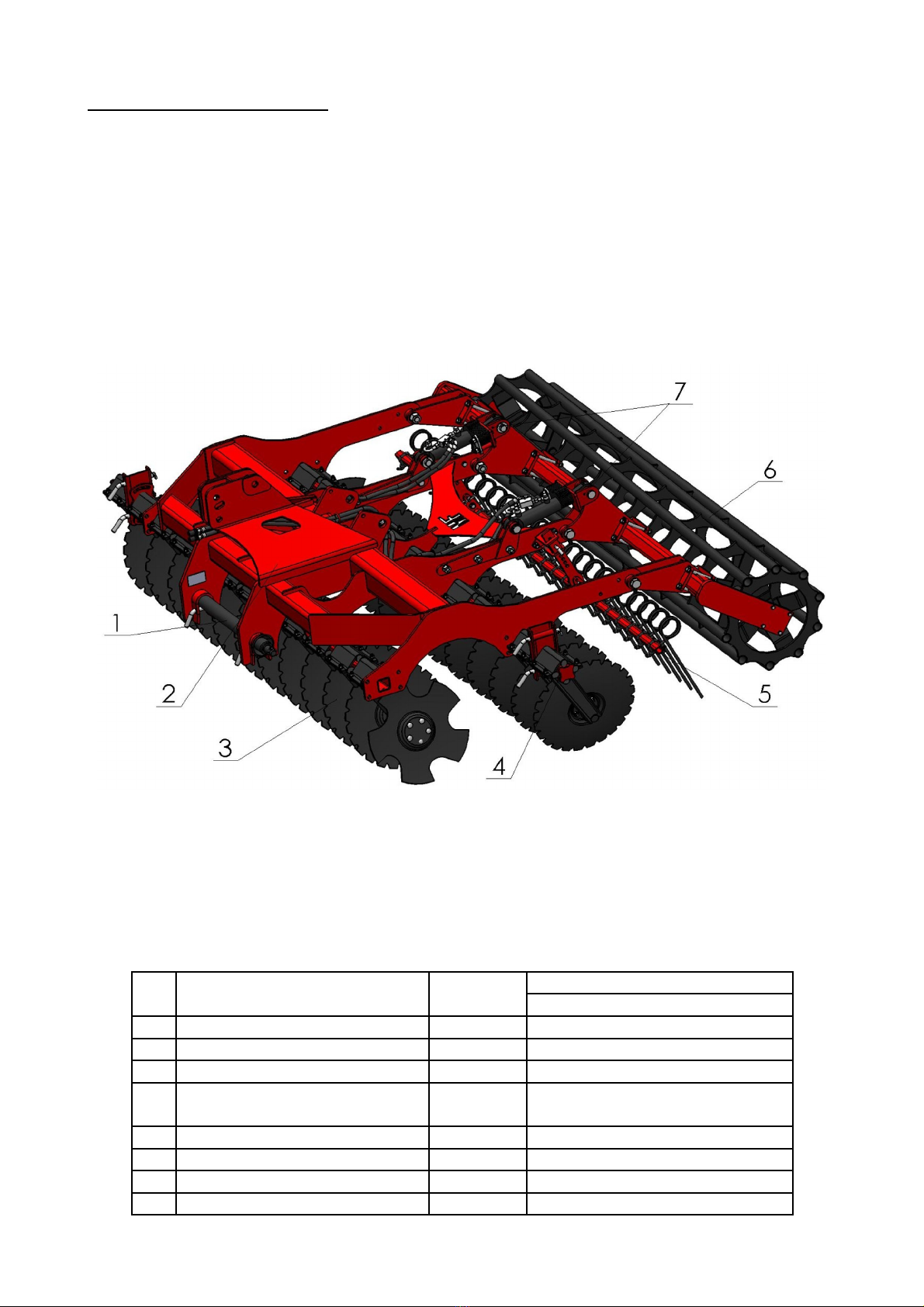
6. MACHINE DESIGN
The suspended KRUK - 3 m type cultivator consists of the following assemblies and
subassemblies
• main frame with a 3 point suspension system, to which two folding external plate supports
are attached, and the harrow disks are attached to the frame;
• beams for lower hitches;
• packer brackets with hydraulic or mechanical adjustment of operating depth which allow for
compacting of the opened soil to obtain the optimum soil structure for sowing;
• beams with spring-held teeth with operating depth and inclination angle adjustment;
• double acting hydraulic cylinders with cables (for the hydraulic operation adjustment
variant).
Fig. 3 KRUK Cultivator
1 - beam for lower hitches, 2 - machine frame, 3 - harrow disks, 4 - folding support for external
plate, 5 - tines, 6 - round Packer, 7 - working depth adjustment (hydraulic or mechanical).
6.1 TECHNICAL CHARACTERISTICS OF THE KRUK U-710 AND U-710/1
CULTIVATORS
Item Parameters Unit Cultivator type
KRUK U-740
1 Cultivator type - suspended
2 Service width m 3
3 No. of discs pcs 24
4 Packer type - pipe (Ø600)
- Packer (Ø500)
5 Disc diameter mm Ø560
6 No. of scrapers pcs 24
7 Depth adjustment range cm from 5 cm to 15 cm
8 Disc pitch mm 250
12

9 Working speed km/h 8-13
10 Efficiency ha/h 3.0-5.0
11 Power demand HP
kW
110-130
81-96
12 Operation persons operator
13 Dimensions
Length/Width/Height
mm 2765/1380/3430
14 Weight /with packer/ kg 1800
15 Hitch category - 3
7. DELIVERY AND LOADING ON MEANS OF TRANSPORT
The machine is supplied to the user partially disassembled. How much the machine is
disassembled depends on the used mean of transport. While loading and unloading the machine,
parts of the frame indicated as lifting points with appropriate pictograms should be used for lifting
the machine see section 3.4.
8. OPERATION AND USE
8.1 PREPARATION OF THE MACHINE
While preparing the machine to work it is required to check its technical condition, most
importantly the condition of the working elements.
In addition it is required to
• check the condition of the bolted joints,
• check the folding and unfolding of the machine,
• check the condition of the hydraulic lines and actuators - whether there are any leaks,
• check whether the discs and packer rotate freely by rotating them by hand,
•lubricate the elements of the machine in accordance with the guidelines specified
in section 8.5.
The machine's hydraulic system is filled with Renolin VG46 hydraulic fluid manufactured
by FUCHS. It is allowed to mix it with the hydraulic liquid with the oil from the tractor's hydraulic
system.
8.2 COUPLING THE MACHINE TO THE TRACTOR
To safely and securely couple the machine to the tractor it should be placed on a firm and
level ground.
To couple the machine to the tractor it is required to perform the following actions
• reverse the tractor to a distance which allows to couple the machine with the tractor's lower
hitch,
• attach the upper hitch of the 3 point hitch to the machine and remove any play,
• attach the hydraulic lines of the machine to the tractor's external hydraulic system,
• raise the machine,
• check the leaktightness of the machine's hydraulic system, the hydraulic lines may not be
bent or damaged,
13

8.3 MACHINE ADJUSTMENT
8.3.1 ADJUSTMENT OF THE HARROW DISKS' WORKING DEPTH
The working depth of the harrow disks may be adjusted using the tractor's three point hitch
or the mechanical or hydraulic shaft adjustment mechanism.
In case of the mechanical adjustment the depth is adjusted by changing the length of the
turnbuckles.
In case of hydraulic depth control the adjustments are made using the hydraulic control
levers inside the tractor's cabin by changing the number of pressure plates of the actuators placed on
the piston rod (fig. 4 - item A).
8.3.2 WORKING DEPTH AND TINE ANGLE ADJUSTMENT
The adjustment of the tine working depth is performed using pins placed in appropriate
openings in the plough frog secured with a cotter pin (fig 4. - item B).
The angle may be adjusted using the lower scraper attachment pins (fig. 4 - item C).
Fig. 4. Machine operation adjustment.
WARNING - Remember to always check the positioning o unused pressure plates o the
hydraulic actuator to avoid damaging the hydraulic adjustment system.
8.4 OPERATION OF THE MACHINE
Before commencing fieldwork using the machine it is required to
• remove the warning markings,
• unfold the machine to its working position (external disks),
• set the machines working depth,
• lower the tractor hitch and set it to floating mode.
If during operation the machine becomes clogged with vegetation remains it must be cleared
by raising the machine for a moment using the tractor's hydraulic system.
14
Hydraulic adjustment
Mechanical adjustment

The machine should be adjusted during the first pass. If the machine is properly levelled the
frame is parallel to the field's surface.
WARNING - Avoid jerky movements while using the machine.
- Make turns gently with the machine raised in the transport position.
- Do not reverse or turn the tractor around with the machine in the working
position as it may cause damage to the machine.
8.5 LUBRICATION AND STORAGE
The durability and efficiency of the machine depends to a large degree on systematic
lubrication. Use mineral oils for lubricating the machine. Before adding grease clear the lubrication
points. The lubrication should be performed according to fig. 5.
Use the ŁT-4S-3 once per season.
The hubs o the harrow disks must be lubricated twice per year:
+ be ore the spring season,
+ be ore the autumn season.
Fig. 5. 1 - hydraulic cylinders / cylinder lug - 4 points (only in the variant with the hydraulic
adjustment of working depth), 2 - bearing set of the harrow disks - 24 points, 3 - bearing assembly
of the shaft - 2 points.
15

Before a long period of storage the machine should be cleaned and all malfunctions should be
repaired. Protect the machine against weather conditions. The machine should be stored in the
unfolded position on a level, hard surface.
9. RESIDUAL RISKS
9.1 DESCRIPTION OF RESIDUAL RISKS
The residual risk results mostly from improper behaviour of the operator caused by lack of
knowledge or attention. The highest residual risk occurs in the following situations
• the machine is operated by minors or persons who are unfamiliar with the operating
instructions,
• the machine is operated by persons under the influence of alcohol or other intoxicants,
• the machine is used for purposes other than specified in the operating instructions,
• a person is present between the tractor and the machine with the tractor's engine running,
• bystanders, especially children are present near the working machine,
• the machine is cleaned while working,
• manipulation of the moving elements while the machine is working,
• checking of the machine's technical condition.
While presenting the residual risk the machine is treated as designed according to the state
of knowledge in the year of its manufacture and maintaining the basic OH&S rules.
9.2 EVALUATION OF THE RESIDUAL RISK
If the following guidelines are adhered to the occurrence of residual risk may be minimised
• always follow the safety regulations described in the operating instructions,
• read and fully understand the operating instructions,
• keep your hands out of hazardous spaces;
• it is forbidden to operate the machine in the presence of bystanders and in particular
children,
• maintenance and repair of the machine may only be performed by trained personnel,
• the machine may only be operated by persons who were trained in its operation and have
familiarised themselves with the operating instructions,
• the machine is protected against access by children,
• the machine is operated by persons in good physical condition who are not under the
influence of any intoxicants.
WARNING!
The residual risks are present when the listed rules and indications are not ollowed.
16

10. WARRANTY CONDITIONS AND WARRANTY SERVICES
The detailed information on the warranty for agricultural equipment is listed in the Civil
Code, Part III, Warranties, art. 577-581. This information should be available at every farming
equipment dealership and service workshop.
The organisations responsible for the execution of warranty services (reseller/dealer) should
be entered in the warranty card during the sale of the machine.
11. LOCATION OF THE MACHINE'S CENTRE OF GRAVITY
Fig. 6. Location of the machine's centre of gravity.
12. STABILITY OF THE UNIT CONSISTING OF THE TRACTOR AND
CULTIVATOR
The tractor should have appropriate ballast at its
front end to provide proper steering and braking
performance. When the machine is coupled the load
on the tractor's front axle must be at least 20% of the
tractor's own weight (Fig. 7).
Remember that the road and the coupled machine
influence the driving characteristics. The driving
style should be adjusted to terrain conditions and
type of soil.
While negotiating corners with the coupled or
suspended machine it is important to bear in mind
the reach and weight of the machine.
17
Fig. 7. Minimum load on the tractor's front axle.
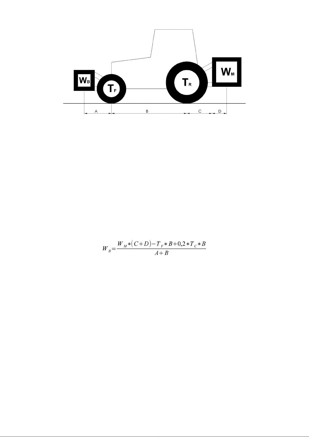
Fig. 8. Static stability.
The ollowing data is required or calculations:
A [m] - distance between the centre of gravity of the front ballast / front mounted equipment
and the centre of the front axle;
B [m] - distance between the tractor's wheels;
C [m] - distance between the centre of the rear axle and the lower hitch ball;
D [m] - distance between the lower hitch ball and the centre of gravity of the rear mounted
machine.
TC[kg] - tractor's own weight;
TF[kg] - front axle load of an unloaded tractor;
TR[kg] - rear axle load of an unloaded tractor;
WM[kg] - total weight of the machine installed in the rear
WB[kg] - total weight of the front ballast/front mounted machine.
18

16-100 SOKÓŁKA, POLAND UL. KRESOWA 62
WARRANTY CARD
FOR THE "KRUK" CULTIVATOR
U-740
The warranty service is provided on behalf of the manufacturer by
................................................................................................................................................................
filled out by the seller
Date of manufacture ....................................... Serial no. ..........................................
Date of sale ........................................ Dealer's signature ..........................................
Customer name.....................................................................................................................................
Address (Postal code / Post o ice)......................................................................................................
Street / Number....................................................Telephone..............................................................
META-FACH Sp. z o.o. reserves the right to introduce changes to the machine's design without
prior notice and without assuming any obligations resulting from those changes. Unauthorised
modifications of the machine shall result in the warranty becoming null and void. During the
service life of the machine only original parts manufactured by METAL-FACH may be used.
19

COMPLAINT CALL NO. DATE
Customer data:
Customer's name and surname / Company name..............................................................................................
City:................................................................................... (Postal code / Post office).......................................
Street................................................Telephone......................................... ax.................................................
Machine name and code
....................................................................... Z/T-.................................
Date of
purchase
Serial number Year of
manufacture
1. When and under what circumstances was the machine's ailure discovered?
............................................................................................................................................................................
............................................................................................................................................................................
............................................................................................................................................................................
............................................................................................................................................................................
............................................................................................................................................................................
2. Comprehensive ault description
............................................................................................................................................................................
............................................................................................................................................................................
............................................................................................................................................................................
............................................................................................................................................................................
............................................................................................................................................................................
3. Customer's proposed mode o complaint call processing
............................................................................................................................................................................
............................................................................................................................................................................
............................................................................................................................................................................
............................................................................................................................................................................
............................................................................................................................................................................
.................................................................................
(legible signature of the customer who filed the complaint)
NOTE: I the complaint is ound to be unjusti ied, all complaint processing costs will
be charged to the complaint applicant.
Customer complaint placed by phone
date..........................................................................
Dealer's stamp
..............................................................
Legible signature of the Dealership Representative
20
Table of contents
Other Metal-Fach Tiller manuals


Popular Tiller manuals by other brands


Agri-Fab
Agri-Fab 45-0365 Assembly instructions

imants
imants SandCat manual

Troy-Bilt
Troy-Bilt 148H Operator's manual

Schiller Grounds Care
Schiller Grounds Care Classen TA18HD Operator's manual

DR Power Equipment
DR Power Equipment PILOT 2C Safety & Operating Instructions

Caravaggi
Caravaggi Ario 100 Series Use and maintenance instruction manual