Metal Man TTWC1 User manual
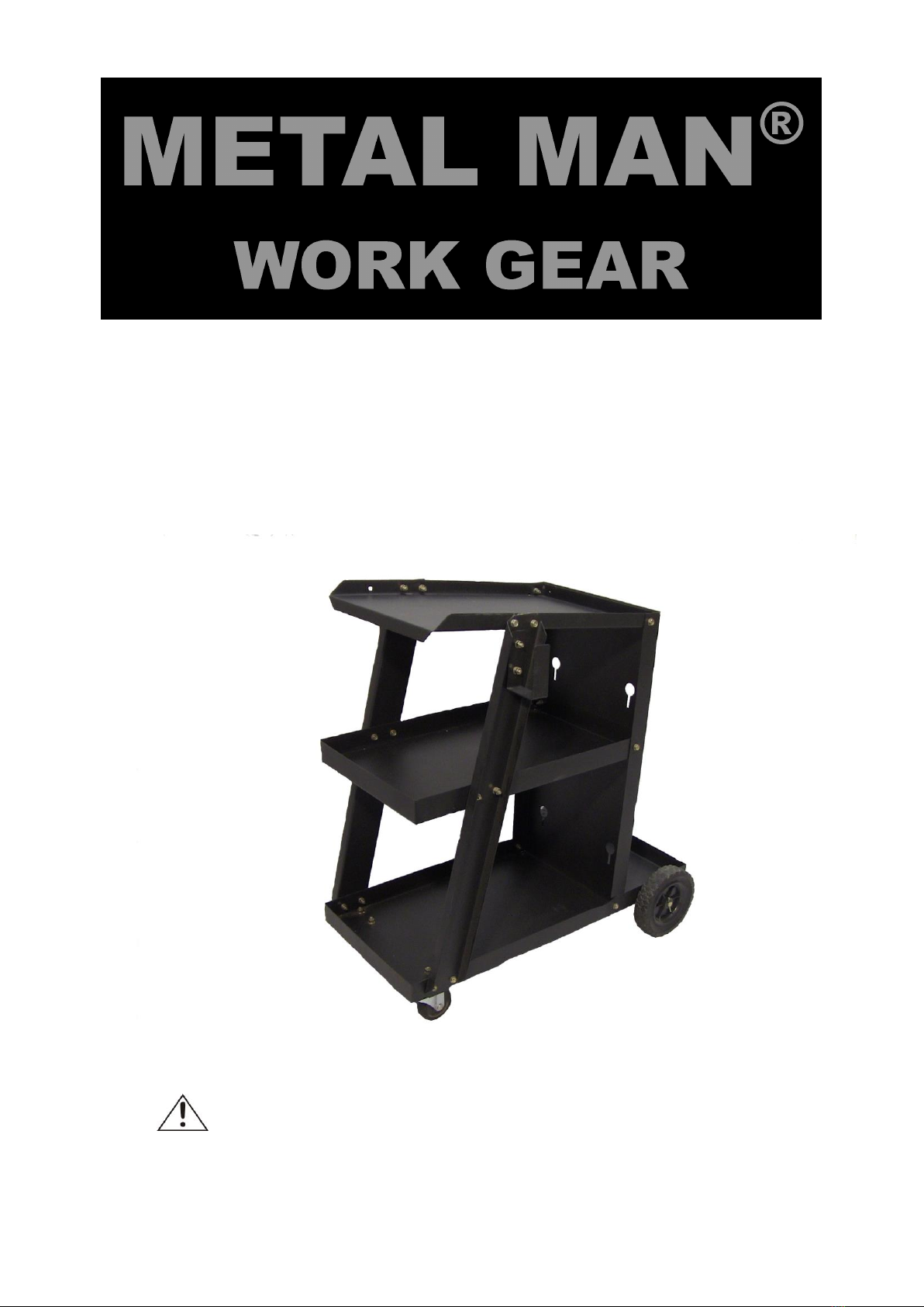
TTWC1 –THREE TIER WELDING CART
OWNER’S MANUAL
5/2015
WARNING:
Read carefully and understand all ASSEMBLY AND OPERATION
INSTRUCTIONS before operating. Failure to follow the safety rules and other
basic safety precautions may result in serious personal injury.

Page of 6
2
METAL MAN WORK GEAR CO
EFFECTIVE June 1, 2015
LIMITED WARRANTY
This warranty applies to the original purchaser and is subject to the terms and conditions listed below. This Limited Warranty is for
new equipment sold after the above date, providing coverage for defects in material and workmanship at the time it is shipped from
the factory.
Limited to the warranty periods below, METAL MAN WORK GEAR CO will repair or replace the item under warranty that fails due
to defects in material and workmanship. METAL MAN WORK GEAR CO must be notified within 30 days of the failure, so as to
provide instructions on how to proceed with the repair of your unit and warranty claim processing. Warranty period begins at the
time the unit is purchased from and Authorized METAL MAN WORK GEAR retailer. Keep your receipt as proof of purchase.
Warranty Periods
90 Days Warranty on METAL MAN Branded welding carts
Limited Warranty
All parts for METAL MAN branded welding carts . This warranty covers the absence of, or defective parts.
Voiding Warranty
Warranty does not apply to: shipping damage, misuse and abuse of the unit and alteration of the unit in any way.
Warranty Claim
This is a Parts only warranty. Contact METAL MAN WORK GEAR CO AT 888-762-4045. Retain your receipt in the case a
warranty claim is needed. No warranty will be provided without the original receipt from an authorized METAL MAN WORK GEAR
dealer.

Page of 6
3
GENERAL SAFETY RULES
WARNING: Read and understand all instructions. Failure to follow all instructions listed
below may result in serious injury or death.
CAUTION: Do not allow persons to operate or assemble this unit until they have read
this manual and have developed a thorough understanding of how this unit works.
WARNING: The warnings, cautions, and instructions discussed in this instruction
manual cannot cover all possible conditions or situations that could occur. It must be
understood by the operator that common sense and caution are factors which cannot be built into
this product, but must be supplied by the operator.
SAVE THESE INSTRUCTIONS
USE AND CARE
Do not modify this unit in any way. Unauthorized modification may impair the function and/or
safety and could affect the life of the equipment. There are specific applications for which this
unit was designed.
Always check for damaged or worn out parts before using this unit. Broken parts will affect
the operation. Replace or repair damaged or worn parts immediately.
Store idle. When this unit is not in use, store it in a secure place out of the reach of children.
Inspect it for good working condition prior to storage and before re-use.
SPECIFICATIONS
Item
Description
Overall Dimensions
27-1/4 in. x 15-3/4 in. x 28-1/4 in.
Product Weight
31 lbs
Load Capacity
110 lbs
Page of 6
4
DESCRIPTION
The METAL MAN TTWC1 Three-Tier Welding Cart is designed to hold portable wire welders,
plasma cutters and TIG Welders. This cart features a three level design to help organize all your
welding tools and accessories. It also has a set of cable wraps on each side for easy and safe
storage of your welding cables. This unit also has an on-board cylinder rack to secure gas cylinders
up to 7 inches in diameter. The 6 inch solid rubber back wheels and the 2 inch solid rubber casters
help maneuver this cart. Your welder or cutter sits on the top shelf, slanted to help get a better view
of the unit controls.
ASSEMBLY
1. Remove all items from the packing material.
2. Starting with the bottom panel, place the bottom panel on a sturdy surface with the side lips
facing up. Find the long slots at the back of the base unit. Insert the Axle Clips into the slots
from the top, then slide the axle through the large hole in the clip. Repeat for both clips.
3. Slide a wheel on each side of the axle.
4. Secure each wheel with a flat washer and cotter pin.
5. Locate the 4 pre-drilled holes at the left front of the bottom panel. Slide a hex bolt through
one pre-drilled hole and then into the matching pre-drilled hole in the flange of one of the
casters. Then secure with a hex nut. Repeat for the other 3 mounting holes.
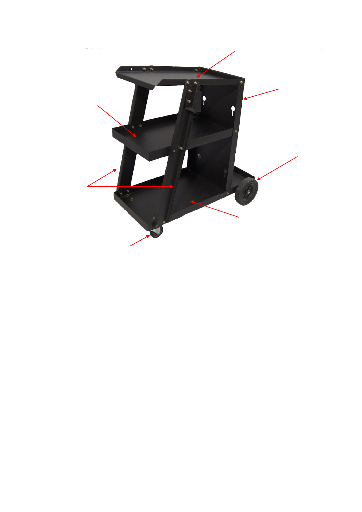
Top
Shelf
Vertical
Supports
Bottom
Shelf
2 Inch
Caster
6 Inch
Wheel
Gas Cylinder
Support
Middle
Shelf

Page of 6
5
ASSEMBLY CONTINUED
6. Repeat the last step for the 4 pre-drilled holes at the right front of the bottom panel.
7. For the remaining assembly steps, we recommend that all hardware be hand tightened to
allow slight movement for the purpose of aligning pre-drilled holes to install hardware. At the
end of these instructions, we will remind you to go back and snug all connections tight.
8. Find the left side vertical panel. With the lips out align to the two pre-drilled holes of the left
side vertical panel with the two pre-drilled holes in the lip of the bottom panel at the front.
They are located right above the left side caster. Insert a hex bolt into the pre-drilled holes in
the left side vertical panel and into the pre-drilled holes in the lip of the bottom panel. Secure
with a hex nut. Repeat for the other mounting hole
9. Repeat the last step for the right side vertical panel.
10. Find the Vertical Cylinder Securement Panel. Position this panel so that the slots in the
panel point down. Insert the down side edge into the bottom panel and align the pre-drilled
holes in the side lips with pre-drilled holes in the lips of the bottom panel that are located just
in front of the back wheels. Insert a hex bolt into the pre-drilled holes in the bottom panel
and then through the pre-drilled holes in the Vertical Cylinder Securement Panel. Secure
with a hex nut. Repeat for both sides.
11. Find the top shelf. Position this shelf so that the lips point up. Align the pre-drilled mounting
holes in the lip of the top shelf with the pre-drilled mounting holes in the Vertical Cylinder
Securement Panel and both the left side and right side vertical side panels. Using a hex bolt,
slide the bolt through the pre-drilled holes in the lip of the top shelf and into the matching
pre-drilled holes in the Vertical Cylinder Securement Panel, the Left Side Vertical Panel and
the Right Side Vertical panel. Secure with a Hex Nut. Repeat for all the mounting holes.
12. Find the middle shelf. Position this shelf so that the lips point up. Align the pre-drilled
mounting holes in the lip of the middle shelf with the pre-drilled mounting holes in the
Vertical Cylinder Securement Panel and both the left side and right side vertical side panels.
Using a hex bolt, slide the bolt through the pre-drilled holes in the lip of the Middle shelf and
into the matching pre-drilled holes in the Vertical Cylinder Securement Panel, the Left Side
Vertical Panel and the Right Side Vertical panel. Secure with a Hex Nut. Repeat for all the
mounting holes.
13. Find one of the cable holders. Position the cable holder so the pre-drilled mounting holes in
the cable holder align with the pre-drilled mounting holes in the Left Side Vertical Panel so
that the opening of the cable holder is up. Using a hex bolt, slide the bolt through the
pre-drilled holes in the cable holder and into the matching pre-drilled holes in the Left Side
Vertical Panel. Secure with a Hex Nut. Repeat for the other mounting hole. Repeat on the
right side.
14. Now go back and tighten all connections.
15. Insert one end of the Cylinder Securement Chain into one of the slots in the Vertical
Cylinder Securement Panel. Let the Chain fall down into the slot to hold it in place. Wrap the
chain around your bottle of shielding gas and insert the other end into the other slot. Let the
Chain fall down into the slot to hold it in place. Adjust the chain as needed to secure the
cylinder. Repeat this step for the remaining Cylinder Securement Chain.

Page of 6
6
DIAGRAM & PARTS LIST
Reference #
Part#
Description
Qty.
1
105100125
TOP SHELF
1
2
105100126
CABLE HOLDER
2
3
105100127
MIDDLE SHELF
1
4
105100128
LEFT SIDE VERTICAL PANEL
1
5
105100129
BOTTOM
1
6
105100130
CASTER
2
7
105100131
HEX NUT
34
8
10510132
RIGHT SIDE VERTICAL PANEL
1
9
105100133
HEX BOLT
34
10
105100001
COTTER PIN
2
11
105100002
FLAT WASHER
4
12
105100003
RUBBER WHEEL
2
13
105100121
AXLE CLIP
2
14
105100134
AXLE
1
15
105100135
VERTICAL CYLINDER SECUREMENT PANEL
1
145200001
NEED HELP LABEL
1
16
105100013
CYLINDER SECUREMENT CHAIN
2
145100001
OWNER’S MANUAL
1
For technical questions contact our welder help line at 1-888-762-4045.
This manual suits for next models
1
Table of contents
Other Metal Man Outdoor Cart manuals


Popular Outdoor Cart manuals by other brands


Carts Vermont
Carts Vermont 20 manual

Westward
Westward 2CZY4 Operating instructions and parts manual

Numatic
Numatic EcoMatic EM-5 Assembly

Bosch
Bosch XL-Cart Operating/safety instructions

Tennsco
Tennsco Modular Cart Top Component Assembly Assembly Instructions/Parts Manual

Clam
Clam POLAR TRAILER HD MAX manual


