Metal Work Elektro BK series User guide
IGB
USO E MANUTENZIONE
ASSE ELETTRICO SENZA STELO A CINGHIA
SERIE ELEKTRO BK
USE AND MAINTENANCE
ELECTRIC AXIS BELT-DRIVEN RODLESS,
SERIES ELEKTRO BK
2
CARATTERISTICHE TECNICHE SPECIFICATIONS
DATI TECNICI VERSIONE
Medium Heavy
Temperatura ambientale ammessa per motorizzazione
PASSO-PASSO °C -10 ÷ +50
BRUSHLESS °C 0 ÷ +40
Massima umidità relativa 90% con 40°C; 57% con 50°C
(non ammessa condensa)
Massimo duty cycle per motorizzazione
PASSO-PASSO 50%
BRUSHLESS 100%
Corsa minima mm 100
Corsa massima mm 3800 1800
Ripetibilità mm ± 0.05
Precisione di posizionamento * mm ± 0.4
Impatto non controllato a fine corsa NON AMMESSO
(prevedere extracorsa minimo 5 mm)
Sensore di posizione per homing Sensore induttivo
Posizione di lavoro Qualsiasi
Rumorosità dBA <66
Tipologia della cinghia RPP5 in poliuretano
con cavi di tensione in acciaio
Allungamento massimo cinghia 0.1%
Corsa / giro puleggia mm 110
Diametro primitivo pulegge mm 35.01
Massima Forza assiale supportabile** N 800
Numero di giri massimo 1/min 3500 3500
Velocità massima (a vuoto) m/s 6 6
Massima accelerazione (a vuoto) m/s250
Massima coppia motrice applicabile alla puleggia Nm 15
* Dato medio indicativo che viene influenzato da vari fattori quali la corsa,
la tipologia del motore, la versione del cilindro, ecc...
** È il carico massimo ammesso sulla cinghia: per il dimensionamento vedere il catalogo generale.
TECHNICAL DATA VERSION
Medium Heavy
Admissible ambient temperature for from -10 to +50
STEPPING motor °C
BRUSHLESS motor °C from 0 to +40
Maximum relative humidity 90% at 40°C; 57% at 50°C
(no condensate)
Maximum duty cycle for 50%
STEPPING motor
BRUSHLESS motor 100%
Minimum stroke mm 100
Maximum stroke mm 3800 1800
Repeatability mm ± 0.05
Positioning accuracy * mm ± 0.4
Uncontrolled impact at the end of stroke NOT ALLOWED
(it provides an extra-stroke minimum 5 mm)
Homing position sensor Inductive sensors
Work position Any
Noise level dBA <66
Type of belt RPP5 in polyurethane
with steel tensioning cables
Maximum belt extension 0.1%
Pulley travel/rotation mm 110
Pulley pitch diameter mm 35.01
Maximum axial force** N 800
Maximum number of revs 1/min 3500 3500
Maximum speed (without load) m/s 6 6
Maximum acceleration without load m/s250
Maximum driving torque applicable to the pulley Nm 15
* Indicative average data that gets influenced by various factors such as the stroke, the type of motor,
the cylinder version, etc...
** Maximum load admissible on the belt: for the sizing, see general catalogue.
3
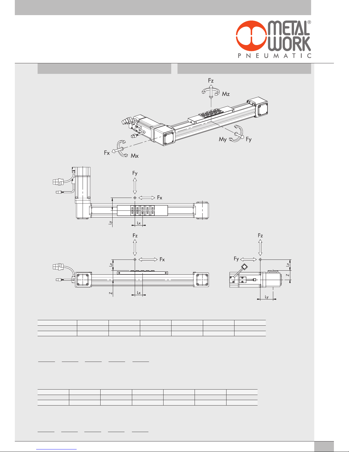
SCHEMA FORZE E MOMENTI DIAGRAM OF FORCES AND MOMENTS
VERIFICA STATICA / STATIC VERIFICATION
Quando sul cilindro agiscono contemporaneamente momenti e/o forze, rispettare le equazioni sotto indicate, dove le lunghezze vanno espresse in metri.
When the cylinder is subjected simultaneously to torque and force, keep to the following equations, where the lengths have to be given in metres.
VERSIONE / VERSION Z [mm] Fy0 max [N] Fz0 max [N] Mx0 max [Nm] My0 max [Nm] Mz0 max [Nm]
Medium 33 1600 900 18 60 140
Heavy 35 5700 5700 40 570 570
N.B.: I valori in tabella sono i carichi massimi applicabili oltre i quali si potrebbero provocare gravi danneggiamenti.
N.B.: The values in the table relates to the maximum admissible loads beyond which serious damage is likely to occur.
Mx = Fz · Ly + Fy · (Lz + z) My = Fz · Lx + Fx · (Lz + z) Mz = Fy · Lx + Fx · Ly
(Mx
)
Mx0 max +(My
)
My0 max +(Mz
)
Mz0 max +(Fy
)
Fy0 max +(Fz
)
Fz0 max ≤1
Mx = Fz · Ly + Fy · (Lz + z) My = Fz · Lx + Fx · (Lz + z) Mz = Fy · Lx + Fx · Ly
(Mx
)
Mx max +(My
)
My max +(Mz
)
Mz max +(Fy
)
Fy max +(Fz
)
Fz max ≤1
VERIFICA DINAMICA / DYNAMIC VERIFICATION
Quando sul cilindro agiscono contemporaneamente momenti e/o forze, rispettare le equazioni sotto indicate, dove le lunghezze vanno espresse in metri.
When the cylinder is subjected simultaneously to torque and force, keep to the following equations, where the lengths have to be given in metres.
VERSIONE Z [mm] Fy max [N] Fz max [N] Mx max [Nm] My max [Nm] Mz max [Nm]
Medium 33 1000 600 12 40 90
Heavy 35 2850 2850 20 285 285
N.B.: I valori in tabella sono calcolati per una vita teorica di 10000 km.
N.B.: The values are calculated on the basis of theoretical useful life of 10000 km.

4
L’asse elettrico va fissato ad una struttura rigida e stabile montando gli
elementi di fissaggio QS sulla coda di rondine ricavata sul profilo estruso.
Il montaggio va effettuato sincerandosi che il numero di elementi di
fissaggio QS sia sufficiente a garantire la stabilità del sistema durante le
fasi di movimento con tutte le masse applicate (per i valori di flessione
elastica vedere il catalogo generale). I componenti da movimentare con
il carrello vengono assemblati utilizzando elementi di fissaggio K oppure
elementi di fissaggio QS.
MONTAGGIO
The electric axis must be secured to a rigid, stable structure, by fitting the
QS fixing elements to the dovetail on the extruded section.
During assembly, make sure there is a sufficient number of QS fixing
elements to guarantee the stability of the system during the movement of all
the applied masses (see our general catalogue for details on elastic flexure
values). The component parts to be handled with the carriage can be
assembled using either the K or the QS fixing elements.
ASSEMBLY
USO HOW TO USE
Gli assi elettrici della serie Elektro BK possono essere montati
orizzontalmente, verticalmente o con inclinazioni intermedie.
POSIZIONE DI MONTAGGIO
The electric axes in the Elektro BK series can be mounted either horizontally,
vertically or at an intermediate angle.
ASSEMBLY POSITION
5
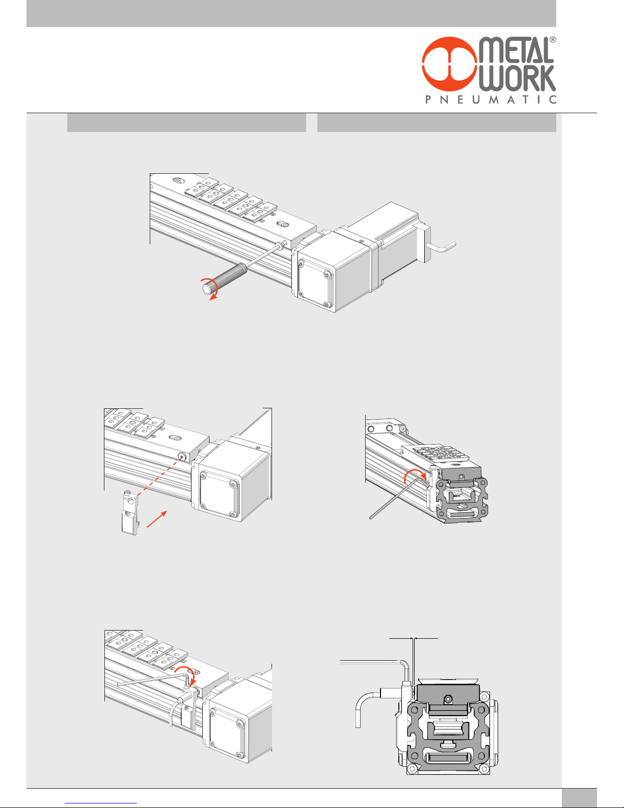
MONTAGGIO DEL SENSORE DI POSIZIONE HOW TO ASSEMBLE THE POSITION SENSOR
2. Inserire il dentino della staffa nella cava presente sui lati della camicia
e con una chiave esagonale da 2 mm serrare il grano inclinato fino
ad ottenere il bloccaggio della staffa. La posizione assiale della staffa
deve essere determinata in relazione al punto in cui si vuole ricevere
il segnale del sensore: l’allineamento fra il foro Ø 6.5 e la testa della vite
speciale (precedentemente avvitata sul carrello) corrisponde grossomodo
alla posizione di lettura del proximity.
1. Fit and tighten the special screw (contained in the “Ø 6.5 inductive
sensor bracket” in the accessories package provided) to any of the four
threaded slots at each corner of the carriage.
2. Insert the bracket tooth into the slot on the sides of the liner and use a
2 mm Allen wrench to tighten the inclined grub screw until the bracket
is locked in position. The axial position of the bracket must be
determined with reference to the point at which you desire to receive the
sensor signal: the alignment between the Ø 6.5 hole and the head of the
special screw (previously fitted to the carriage) roughly corresponds to
the read position of the proximity switch.
3. Inserire il proximity nell’apposito foro della staffa, avendo cura
di mantenere una distanza di circa 1 mm fra la testa di lettura del
proximity e la testa della vite speciale. Serrare con una chiave esagonale
da 2.5 mm la vite superiore al fine di bloccare la posizione del sensore.
3. Insert the proximity switch into the bracket slot, taking care to keep a
clearance of about 1 mm between the read head of the proximity switch
and the head of the special screw. Tighten the upper screw with a
2.5 mm Allen wrench to lock the sensor in position.
1. Avvitare la vite speciale (contenuta nell’accessorio “staffa sensore
induttivo Ø 6.5”) in una delle quattro sedi filettate presenti in ogni
angolo del carrello.
1 mm
6
MONTAGGIO DEL MOTORE (O MOTORIDUTTORI) HOW TO ASSEMBLE THE MOTOR (OR GEARMOTORS)
1. Inserire assialmente il motore portandolo in battuta sulla flangia.
2. Avvitare le 4 viti di fissaggio del motore, serrandole leggermente:
le viti devono soltanto mantenere il motore in battuta sulla flangia, il
serraggio definitivo si effettuerà successivamente.
1.Insert the motor axially until it is fully against the pulley.
2.Slightly tighten the 4 motor fixing screws. At this stage the scews must
only keep the motor in contact with the flange; they will be fully tightened
at a later stage.
N.B.: Il collegamento dei motori (o motoriduttori) alla puleggia del cilindro
senza stelo Elektro BK è realizzato mediante una giunzione rigida, scelta
che ha consentito di poter minimizzare gli ingombri dell’asse.
La corretta funzionalità del sistema richiede però una maggior precisione
nella sequenza di montaggio del motore al fine di garantire il corretto
fissaggio con la puleggia.
N.B.: The motors (or gearmotors) are linked to the pulley of the Elektro
BK rodless cylinder using a rigid coupling joint, which allowed us to
considerable reduce the size of the electric axis.
The correct operation of the system requires, however, greater precision in
the motor assembling sequence in order to ensure the proper fixing of the
pulley.
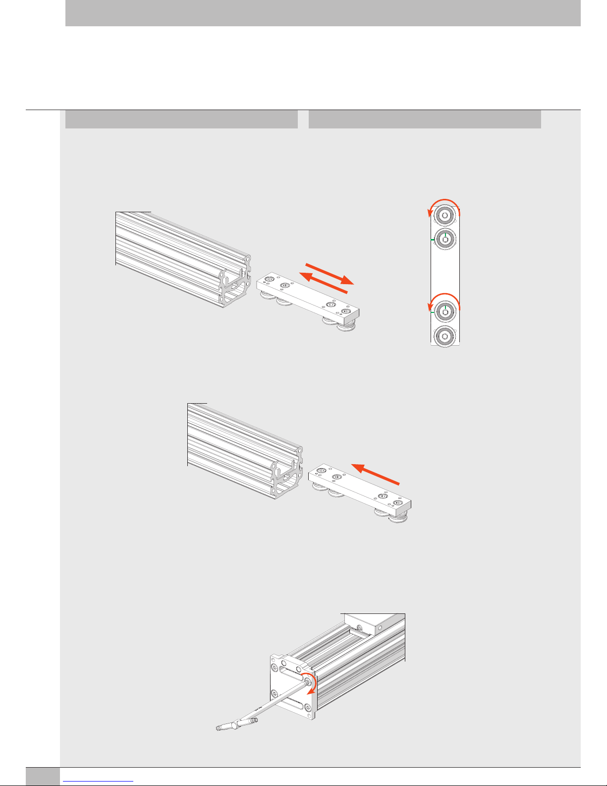
DETTAGLIO DELLA MECCANICA DEL GIUNTO DI COLLEGAMENTO ALL’ALBERO MOTORE
MECHANICAL FEATURES OF THE DRIVING SHAFT COUPLING JOINT

7
4. Serrare la vite del giunto.
5. Mantenendo impegnata la vite del giunto con la chiave esagonale (per
di impedire la rotazione della puleggia) serrare le 3 viti della puleggia.
3. Avvitare unicamente la vite sulla simmetria della puleggia (cerchiata in
verde) fino alla battuta e serrare moderatamente. 3.Turn the screw only on the symmetry of the pulley (circled in green)
until it goes and tighten slightly.
4. Tighten the coupling joint screw.
5. Keep the coupling joint screw engaged with the Allen wrench to prevent
the pulley from rotating, then tighten the 3 pulley screws.
110° 110°
140°

8
7. Rimontare il coperchio. 7.Place the cover back in position.
6. Serrare definitivamente le 4 viti del motore (precedentemente
posizionate) ed riposizionare il grano M5 di chiusura del foro nella
flangia: applicare una goccia di frena filetti medio (blu) per fissare la
posizione del grano a filo della flangia.
6. Fully tighten the 4 previously-positioned motor screws and reposition the
M5 grub screw to close the hole in the flange: apply a drop of
medium-strength threadlocker (blue) to fix the grub screw head flush
with the flange.
N.B.: Il motore va controllato in modo che non vi siano bruschi cambi di velocità.
t
t
V
V
N.B.:The motor must be controlled to avoid any abrupt changes of speed.
9
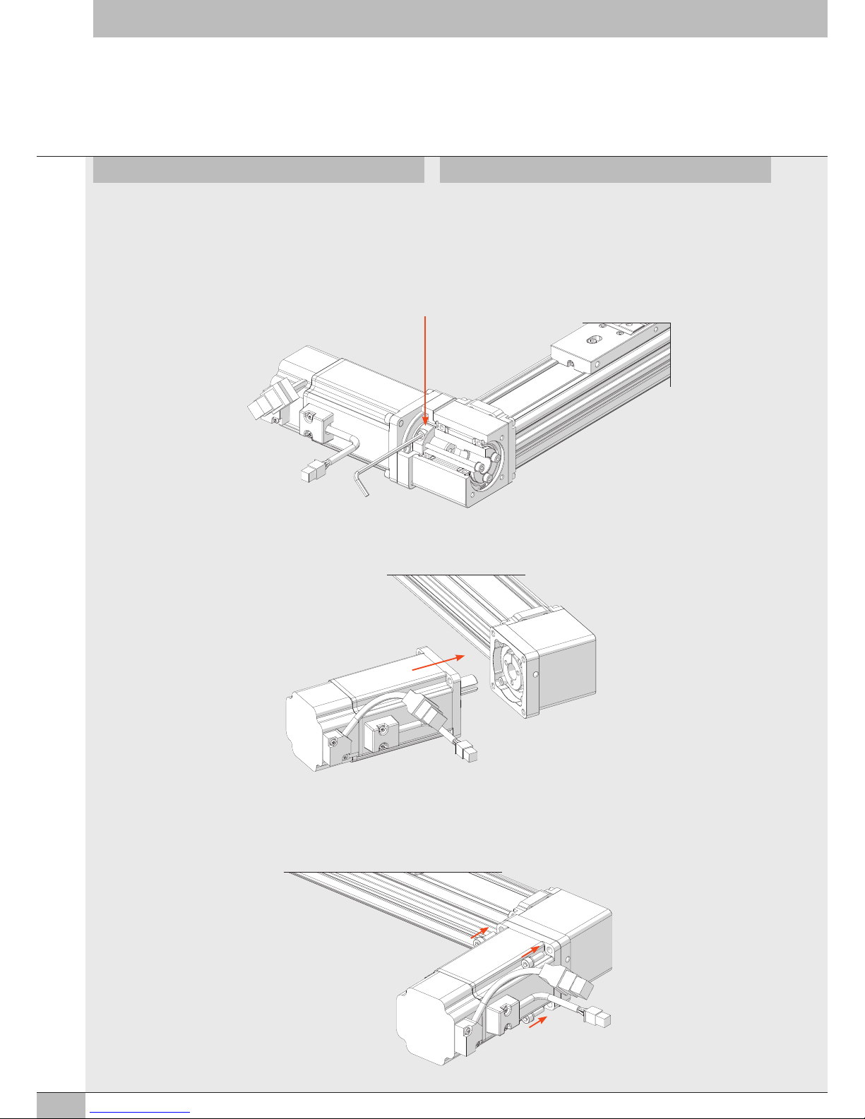
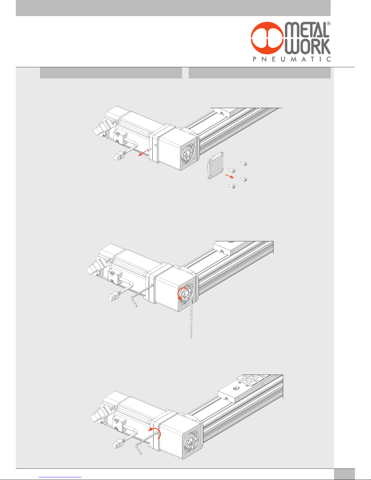
1. Togliere il coperchio sul lato opposto del motore e svitare il grano M4 di
chiusura come da illustrazione. 1.Remove the cover on the opposite side of the motor and unscrew the M4
grub screw, as shown in the figure.
2. Utilizzando una chiave esagonale da 3 mm impegnare la vite del giunto
al fine di impedire la rotazione della puleggia. Allentare le 3 viti della
puleggia con chiave esagonale da 3 mm.
N.B.: Muovere manualmente il carrello per poter individuare la vite del
giunto.
2.Use a 3 mm Allen wrench to engage the coupling joint screw to prevent
the pulley from rotating. Loosen the 3 pulley screws with the 3 mm Allen
wrench.
N.B.:Move the carriage manually to identify the coupling joint screw.
SMONTAGGIO DEL MOTORE (O MOTORIDUTTORI) HOW TO DISASSEMBLE THE MOTOR (OR GEARMOTORS)
3. Allentare la vite di serraggio del giunto: una volta allentata compiere un
ulteriore giro della vite a vuoto al fine di garantire il completo
sbloccaggio del giunto.
3.Loosen the coupling joint screw, then idle rotate the screw a further turn
to release the coupling joint fully.
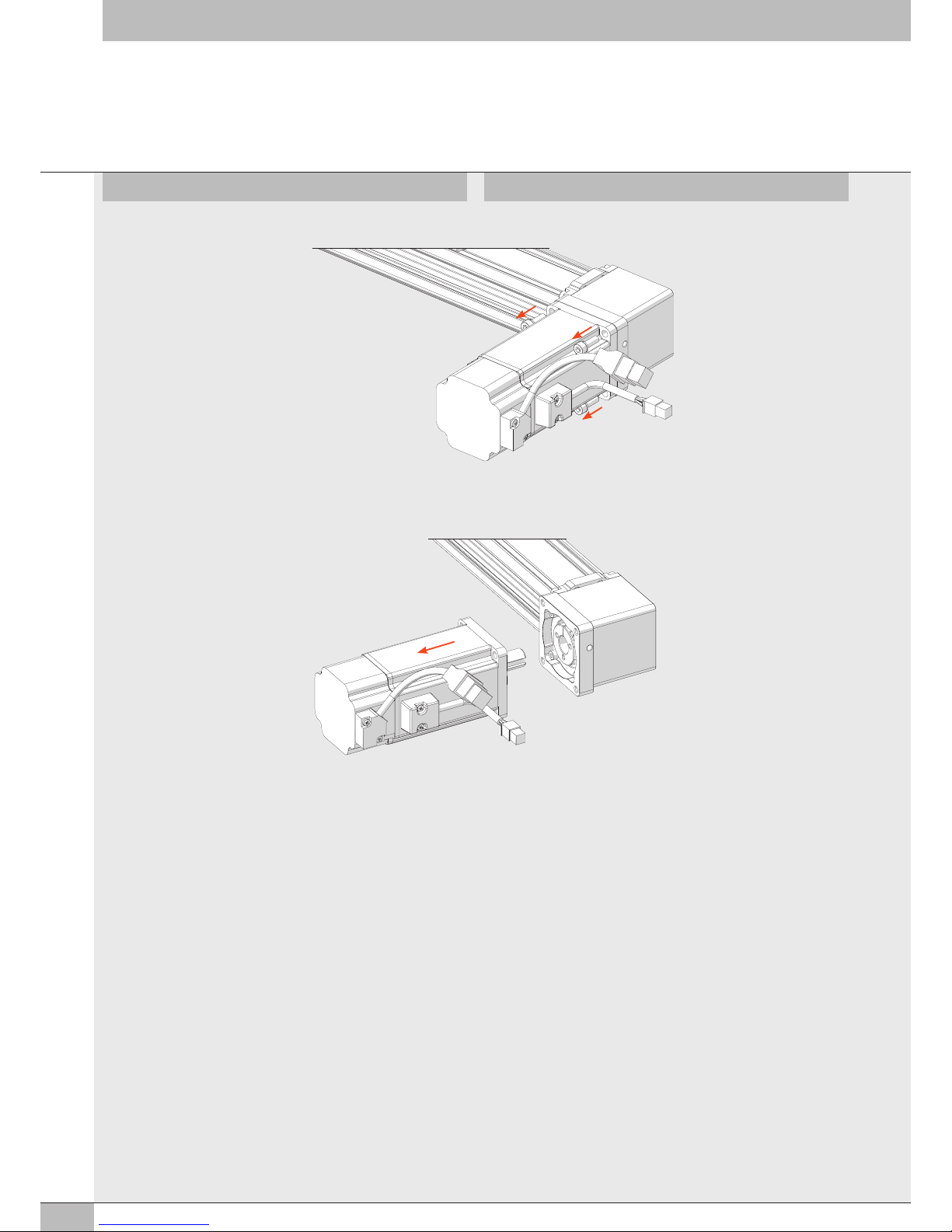
10
5. Sfilare assialmente il motore. 5.Pull out the motor axially.
4. Smontare le 4 viti di fissaggio del motore. 4.Remove the 4 motor fixing screws.
11
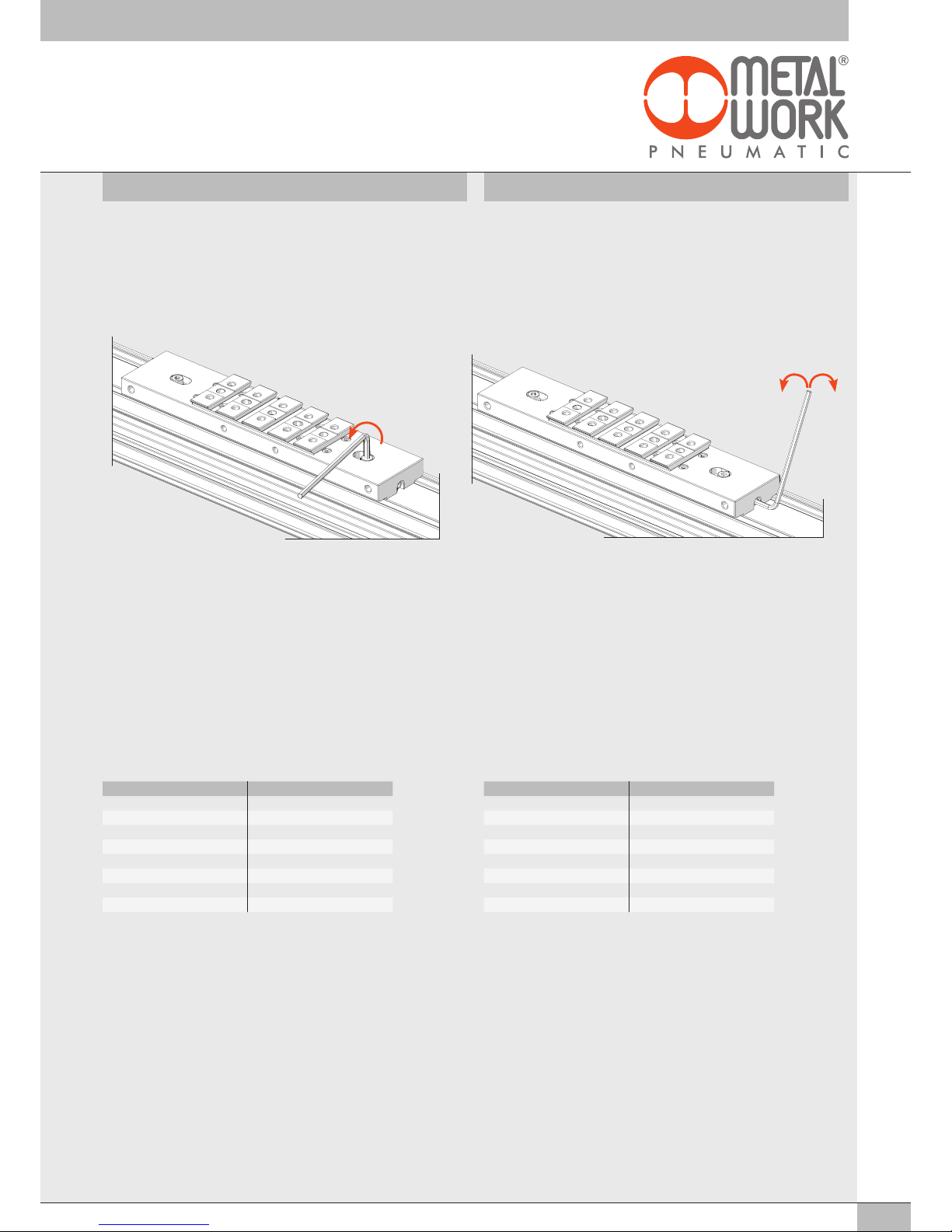
TENSIONAMENTO DELLA CINGHIA BELT TENSIONING
La corretta regolazione della tensione della cinghia è indispensabile
per poter garantire un corretto ed affidabile funzionamento dell’asse.
É necessario disporre di un frequenzimetro per poter procedere con la
regolazione della tensione della cinghia. Il peso lineare della cinghia del
cilindro senza stelo elektro BK è di 0.109 kg/m.
N.B.: Rispettare le istruzioni a corredo del frequenzimetro in uso per il
corretto rilievo della tensione.
1. Allentare con una chiave esagonale da 3 mm per circa un giro la vite di
bloccaggio della piastrina porta cinghia.
2. Utilizzando una chiave esagonale da 2.5 mm procedere alla
regolazione della tensione della cinghia rispettando i valori indicati nella
tabella: ruotando in senso orario il grano si ottiene un aumento della
tensione, ruotandolo in senso antiorario si ottiene una diminuzione della
tensione.
3. Una volta raggiunta la corretta tensione procedere al bloccaggio della
vite superiore (precedentemente allentata) utilizzando una chiave
esagonale da 3 mm.
N.B.: Procedere con la regolazione cercando di operare su entrambe le
estremità del carrello.
*
I cilindri con corsa inferiore a 250 mm rendono molto difficoltoso ed impreciso il
rilievo con il frequenzimetro, pertanto l’operatore dovrà procedere valutando secondo
esperienza la bontà del tensionamento effettuato, preferendo una tensione leggermente
più bassa rispetto ad un tensionamento eccessivo.
CORSA [mm] TENSIONE [kg]
*da 100 a 250 20
da 250 a 750 25
da 750 a 1500 30
da 1500 a 2000 35
da 2000 a 2500 40
da 2500 a 3000 45
da 3000 a 3800 50
The proper tensioning of the belt is of vital importance to ensure correct
and reliable operation of the electric axis. A frequency metre must be used
to adjust the belt tension. The linear weight of the belt of the Elektro BK
rodless cylinder is 0.109 kg/m.
N.B.: For correct measurement, strictly follow the instructions provided with
the frequency metre.
1. Rotate the screw securing the belt plate by about half a turn, using a 3
mm Allen wrench.
2. Adjust the belt tension with a 2.5 mm Allen wrench, keeping to the
values shown in the table, as follows: rotate the grub screw clockwise to
increase the tension and anticlockwise to decrease it.
3. When the correct tension has been reached, fully tighten the previously
loosened upper screw, using the 3 mm Allen wrench.
N.B.:Adjust the tension trying to operate on both ends of the carriage.
* With cylinders with a stroke of less than 250 mm, the measurement with the frequency
metre is difficult and inaccurate. In this case, it is up to the operator to evaluate the
measurement according to his experience, by privileging a slightly less tensioned belt
than an excessively taut belt.
STROKE [mm] VOLTAGE [kg]
*100 to 250 20
250 to 750 25
750 to 1500 30
1500 to 2000 35
2000 to 2500 40
2500 to 3000 45
3000 to 3800 50
+-

12
1. - Allentare con una chiave esagonale da 3 mm per circa un giro le viti
di bloccaggio della piastra di bloccaggio della cinghia.
- Svitare i grani di regolazione con una chiave esagonale da 2.5 mm
fino ad ottenere il completo de-tensionamento della cinghia.
- Svitare con una chiave esagonale da 3 mm solamente una delle due
viti della piastra di bloccaggio della cinghia: scegliere possibilmente il
lato della testata senza motore.
SOSTITUZIONE ROTELLE DISASSEMBLING THE WHEELS
2. Svitare con una chiave esagonale da 3 mm le quattro viti di fissaggio
della testata. 2. Loosen the four head screws with a 3 mm Allen wrench.
1. - Loosen the belt-locking plate screws by about a turn, using a 3 mm
Allen wrench.
- Loosen the grub screw with a 2.5 mm Allen wrench until the belt is
fully loosened.
- Loosen only one of the two belt-locking plate screws with a 3 mm
Allen wrench: possibly the one on the head without motor side.
+-
aCINGHIA DENTATA
bCARRELLO CON INTERFACCIA
V-LOCK
cPIASTRA DI BLOCCAGGIO
DELLA CINGHIA
dTESTATA
eSUPPORTO TESTATA
fROTAIA DI GUIDA PER ROTELLE
D’ACCIAIO
gROTELLA IN ACCIAIO TEMPRATO
hSUPPORTO CUSCINETTI
aTOOTHED BELT
bSLIDE WITH V-LOCK INTERFACE
cBELT-LOCKING PLATE
dHEAD
eHEAD SUPPORT
fGUIDING RAIL FOR STEEL WHEELS
gWHEELS IN HARDENED STEEL
hBEARING SUPPORT
a
f
g
c
b
d
h
e

13
3. Togliendo la testata la cinghia si sfilerà di conseguenza. 3. When removing the head, the belt will slip off accordingly.
4. Svitare con una chiave torx TX25 le quattro viti di fissaggio della piastra
di supporto della testata. 4. Loosen the four head plate screws with a TX25 torx screwdriver.
5. Svitare con una chiave esagonale da 2.5 mm le otto viti di fissaggio
carrello. 5. Loosen the eight slide screws with a 2.5 mm Allen wrench.

14
6. Sfilare il supporto cuscinetti. 6. Pull out the bearing support.
7. Svitare le quattro rotelle con due chiavi esagonali da 4 mm, avendo
cura di procedere allo svitamento delle viti mantenendo ferma la chiave
innestata nella rotella.
7. Loosen the four wheels with two 4 mm Allen wrenches, taking care to
turn the screws keeping the wrench engaged in the wheel.
8. Il sistema è così composto:
- un supporto cuscinetti;
- due rotelle concentriche che verranno montate sull’estremità;
- due rotelle eccentriche che verranno montate sull’interno.
8. The system consists of:
- a bearing support;
- two concentric wheels to be mounted on the head;
- two eccentric wheels to be mounted inside.
tacche di riferimento
reference marks

15
11. Avvitare fino a puntare le due rotelle eccentriche nei fori interni del
supporto cuscinetti con due chiavi esagonali da 4 mm. Verificare che i
segni sul supporto cuscinetti e sulle rotelle sia come in figura.
11. Turn the two 4 mm Allen wrenches to screw in the two eccentric wheels
until they engage the internal holes of the bearing support. Check that
the marks on the bearing support and the wheels are in the position
shown in the figure.
10. Le rotelle eccentriche devono essere montate sul supporto cuscinetti in
posizione neutra e suggeriamo di seguire la procedura che segue per
agevolare il montaggio.
Segnare con un pennarello:
u
il lato più spesso delle rotelle eccentriche;
u
il lato opposto rispetto alle due tacche di riferimento presenti sul
supporto cuscinetti.
10. The eccentric wheels must be mounted on the bearing support in a
neutral position and we suggest to proceed as follows to facilitate
assembly.
Mark with a felt-tip pen:
u
the thicker side of the eccentric wheels;
u
the side opposite the two reference marks on the bearing support.
9. Avvitare a fondo le due rotelle concentriche nei fori esterni del
supporto cuscinetti con due chiavi esagonali da 4 mm.
É importante non dimenticare di applicare le rondelle elastiche sotto la
testa delle viti.
9. Fully tighten the two concentric wheels in the outer holes of the bearing
support with two 4 mm Allen wrenches. It is important not to forget to
apply the spring washers under the screw heads.
A
B
A
B
u
B
u
B
rotella eccentrica
eccentric wheel
rotella concentrica
concentric wheel
u
A
16
13. Infilare il supporto cuscinetti nella rotaia di guida. 13. Insert the bearing support into the guiding rail.
14. Avvitare con una chiave torx TX25 le quattro viti di fissaggio della
piastra di supporto testata.
12. Verificare il corretto tiraggio delle rotelle inserendo e togliendo il
carello dalla rotaia di guida.
Il carrello non deve avere gioco e deve entrare con una leggera
interferenza nella rotaia di guida.
Se così non fosse le rotelle devono essere ruotate nella stessa misura e
nella stessa direzione (antioraria) come in figura.
12. Check that the wheels are tightened properly by inserting and removing
the slide from the guiding rail.
The slide must not create any play and move in with a slight
interference in the guiding rail.
If this is not the case, the wheels must be turned to the same quantity
and in the same direction (anti-clockwise), as shown in the figure.
14. Tighten the four head plate screws with a TX25 torx screwdriver.

17
15. Avvitare con una chiave esagonale da 3 mm le quattro viti di fissaggio
della testata. 15. Tighten the four head screws with a 3 mm Allen wrench.
16. Tracciare una riga con il pennarello sul dorso della cinghia in
corrispondenza dell’ultimo dente in presa sulla piastra di bloccaggio
della cinghia (il segno potrebbe già essere presente).
16. With the felt-tip pen, draw a line on the back of the belt at the last tooth
engaging the belt-locking plate (the mark is probably already present).
17. - Inserire la cinghia nella piastra di bloccaggio della cinghia
(precedentemente rimontata sul carrello) e bloccarla assicurandosi di
vedere il segno del pennarello sulla cinghia in corrispondenza
dell’estremità del carello (questa accortezza è necessaria per
garantire l’accoppiamento di tutti i denti della cinghia nella relativa
sede della piastra di bloccaggio della cinghia).
- Avvitare la vite serrando leggermente (il bloccaggio sarà effettuato
dopo il tensionamento della cinghia).
- Procedere al Tensionamento della cinghia (e all’eventuale
rimontaggio del motore) come da specifiche istruzioni.
17. - Insert the belt into its belt-locking plate (previously mounted on the
slide) and lock it in position, making sure that the mark is clearly
visible at the end of the slide (this precaution is required to ensure
that all belt teeth engage properly in the belt-locking plate housing).
- Slightly tighten the screw (to be tightened fully after the belt has
been tensioned).
- Tension the belt (and reinstall the motor, if any) following the
instructions provided.
www.metalwork.eu
ZXTVAF001 - IM02_02/2019
Table of contents
Other Metal Work Controllers manuals


Popular Controllers manuals by other brands


Omron
Omron CJ - PROGRAMMING 08-2008 Reference manual

CMC
CMC Airmaster R1 Hardware installation guide

Power-Tronics
Power-Tronics XR5B-400 manual

Pentair
Pentair AVID XA+ Installation & operating instructions

ARCA
ARCA 814 Series Operating and maintenance manual

Philips
Philips Dynalite DMRC210DA-RJ12 installation instructions


