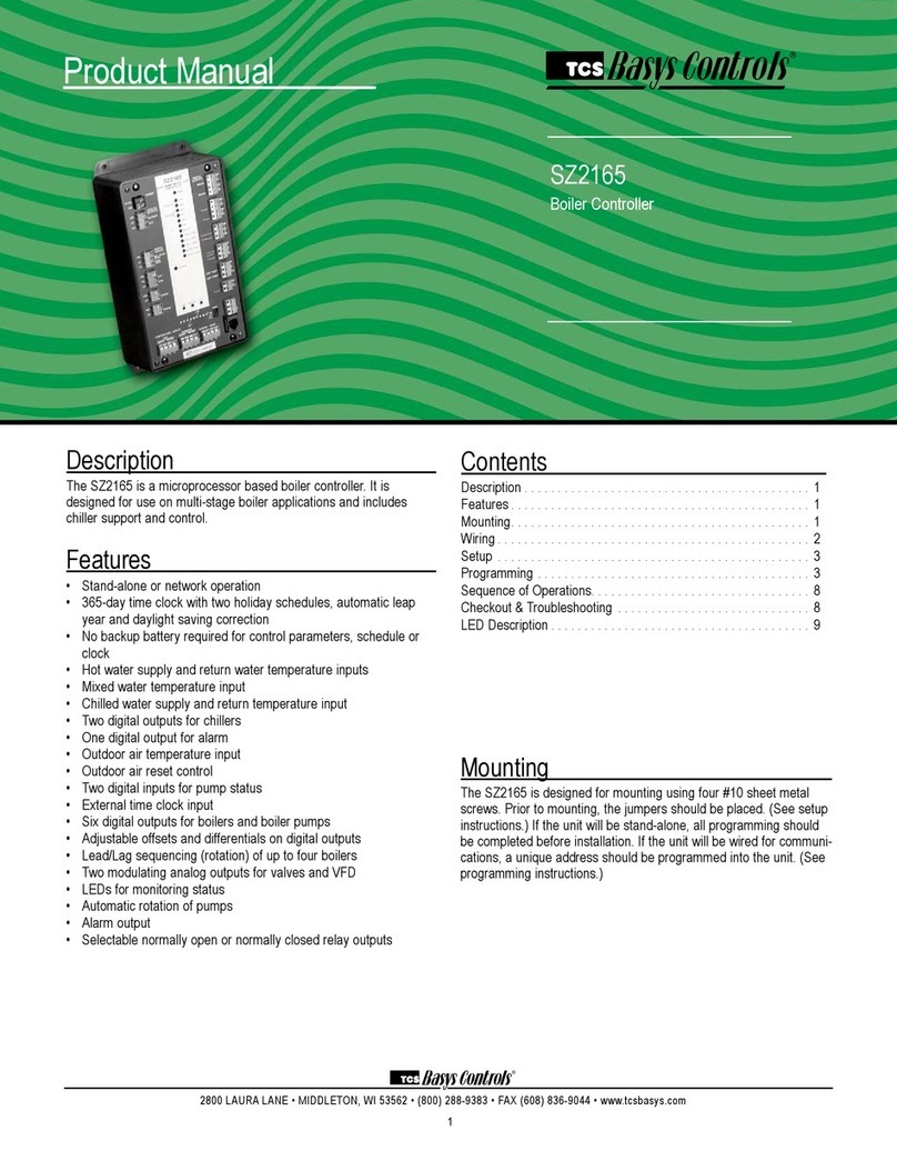
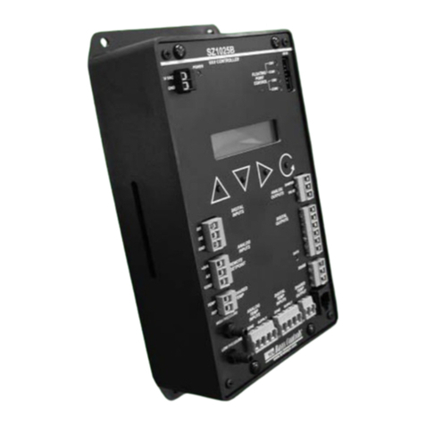
TCS Basys Controls SZ1143b User manual

2800 LAURA LANE • MIDDLETON, WI 53562 • (800) 288-9383 • FAX (608) 836-9044 • www.tcsbasys.com
1
SZ1143b
General Purpose Controller
Product Manual
Description
The SZ1143b is a microprocessor-based general pur-
pose controller. Because it has four distinct control
sequences, it is designed for use in a wide variety of
applications. These applications are: general control,
remote setpoint control, general input reset ratio control
and differential input (i.e. temperature, pressure, humid-
ity, etc.) control.
Features
• Two 4 to 20 mA analog inputs suitable for a broad
variety of transducers
• Two digital inputs for switches, alarms, clocks, etc.
• One 4-20 mA modulating output
• Two relay outputs
• Adjustable P+I+D control on modulating output
• Adjustable offsets and differentials on relay outputs
• Application sequences include:
• Humidification
• Dehumidification
• Dew Point Control
• High/Low Signal Control
• Differential Temperature
• Differential Pressure
• Static Pressure
• Hot or Chilled Water
• Hot or Chilled Water Reset
• Stand-alone or network operation
Mounting
The SZ1143b is designed for mounting using two #10
sheet metal screws.
Contents
Description . . . . . . . . . . . . . . . . . . . . . . . . . . . . . . . . . . 1
Features ....................................1
Mounting....................................1
Wiring ......................................2
Programming ................................3
Operation ...................................5
Checkout & Troubleshooting ....................7
LED Description ..............................8
Communicating Thermostats
Communicating Thermostats

2800 LAURA LANE • MIDDLETON, WI 53562 • (800) 288-9383 • FAX (608) 836-9044 • www.tcsbasys.com
2
Wiring
The SZ1143b uses terminal designations for wiring. See
diagram below.
TRANSMITTER WIRING
The SZ1143b accepts two 2-wire, 4-20mA transmitters.
Use our TH Series for relative humidity sensing, TS/TX
Series for temperature sensing, or TD/TL Series for dif-
ferential air sensing.
POWERING THE SZ1143b
The SZ1143b is powered from 24 VAC +/- 20 %.
Caution: Do not connect to 120 VAC. When
multiple TCS Basys Controls devices are using a
single transformer, the polarity of the power wir-
ing must be maintained because all TCS devices
are half-wave rectified and have common return
paths.
If wiring for communications, dedicated power must be
used to power the controller. Several S series controllers
may be powered from the same transformer, provided
that the transformer has sufficient power. (Supertrols
require 5 VA @ 24VAC.)
AI1 0
AI2 0

2800 LAURA LANE • MIDDLETON, WI 53562 • (800) 288-9383 • FAX (608) 836-9044 • www.tcsbasys.com
3
Programming
The SZ1143b may be programmed through the display
and keypad, or with a PC.
If programming with a PC, the following must be set
through the keypad prior to programming:
• Address (step #2)
• Baud rate (step #3)
For more information on programming through the PC,
consult your TCS software manual.
PROGRAMMING THROUGH THE KEYPAD
To access the programming screens, press both the
“Scroll” and “Next” keys simultaneously.
Scroll Key - The "Scroll" key is also used to
save any changes to the "current" screen and
advance to the next screen while program-
ming. The "Scroll" key is used to enter the
Programming Mode when pressed with the
"Next" key.
Next Key - Used to enter Programming Mode
when pressed with the “Scroll” key. Also used to
exit programming without saving changes to the
current screen. In monitoring mode, the “Next” key is used
to scroll backwards.
Increment/Decrement Keys - Used to select
the desired value.
Main Monitoring Screen. Press the
scroll and next buttons to access the fol-
lowing screens.
Access Code Entry Screen. Enter
the access code. If the wrong code is
entered, the program reverts to the main
screen. 248 is the default access code.
Controller Address Screen. If using a
PC to access the SZ1143b, set a unique
address from 0 to 255, excluding 248.
Communication Baud Rate Screen. If
using a PC to access the SZ1143b, all
controllers on a network must be set to
the same baud rate. Choose between
2.4K, 4.8K, 9.6K and 19.2K.
Enable High/Low. Select yes to enable
High/Low control.
High/Low Output Screen. Select
whether you would like to pass the low
or the high analog inout (This screen
only appears if High/Low Control mode
is enabled).
Analog Output Range Screen. Choose
whether the analog output range will be
0-20mA or 4-20mA. (This screen is the
last screen if High/Low control mode is
enabled, and is the same as step 22
when not enabled).
Enable Dew Point Control. Select yes
to enable dew point control. (Skip to step
14 if dew point is selected.)
AI1 Low Limit Span Screen. Enter the
lowest value of the span range of the
transmitter connected to AI1 (i.e., value
at 4mA). Note: Automatically set to 0 if
dew point control is selected.
AI1 High Limit Span Screen. Enter the
highest value of the span range of the
transmitter connected to AI1 (i.e., value
at 20mA). Note: Automatically set to 100
if dew point control is selected.
AI2 Low Limit Span Screen. Enter the
lowest value of the span range of the
transmitter connected to AI2 (i.e., value
at 4mA). Note: Automatically set to 0 if
dew point control is selected.
AI2 High Limit Span Screen. Enter the
highest value of the span range of the
transmitter connected to AI2 (i.e., value
at 20mA). Note: Automatically set to 100
if dew point control is selected.
AI1 Decimal Point Screen. For display
purposes, the SZ1143b allows a deci-
mal point to be turned on. No scaling
is done. Enter "0" for no decimal point,
"XX.X" for a decimal point in the tenths
position, "X.XX" for a decimal point in
the hundredth position or ".XXX" for a
decimal point in the thousandths posi-
tion.
AI2 Decimal Point Screen. For display
purposes, the SZ1143b allows a deci-
mal point to be turned on. No scaling
is done. Enter "0" for no decimal point,
"XX.X" for a decimal point in the tenths
position, "X.XX" for a decimal point in
the hundredth position or ".XXX" for a
decimal point in the thousandths posi-
tion.
ENTER ACCESS
CODE 0
1.
SET ADDRESS:
0
2.
SET BAUD RATE:
9.6K
3.
AI1 71
AI2 71
+
ENABLE DEW POINT
CONTROL: NO
7.
AI1 SPAN LOW
LIMIT: 0
8.
AI1 SPAN HIGH
LIMIT: 0
9.
AI2 SPAN LOW
LIMIT: 0
10.
AI2 SPAN HIGH
LIMIT: 100
11.
SET AI1 DECIMAL
POINT: NONE
12.
SET AI2 DECIMAL
POINT: NONE
13.
ENABLE HIGH/LOW
CONTROL: NO
4.
SELECT HIGH/LOW
OUTPUT: LOW
5.
MOD OUT
RANGE: 4-20MA
6.

2800 LAURA LANE • MIDDLETON, WI 53562 • (800) 288-9383 • FAX (608) 836-9044 • www.tcsbasys.com
4
Occupied Deadband Screen. Enter
an occupied deadband. This is +/- the
setpoint where no control is done, during
the occupied time period. This is a num-
ber from 0 to 100% of input span.
Unoccupied Deadband Screen. Enter
an unoccupied deadband. This is +/- the
setpoint where no control is done, dur-
ing the unoccupied time period. This is a
number from 0 to 100% of input span.
AI2 Control Mode Screen. Choose
the control mode for AI2. Select from
Remote Setpoint, Reset or Monitor.
Select Monitor if AI2 is not used. Note:
Must be MONITOR if dew point control
is selected.
Setpoint Low Limit Value Screen.
Enter a setpoint low limit value. The set-
point will not be allowed to be set lower
than this setting.
Setpoint High Limit Value Screen.
Enter a setpoint high limit value. The set-
point will not be allowed to be set higher
than this setting.
Setpoint Screen. Enter a setpoint value
for control. (This screen does not appear
if the AI2 Control Mode is chosen to be
Remote Setpoint.)
Reset Setpoint Screen. Enter a setpoint
value for AI2. (This screen only appears
if the AI2 Control Mode is chosen to be
Reset.)
Reset Ratio Factor Screen. Enter a
reset ratio factor. This is the number
of units +/- (%RH, °F, etc.) that the AI1
Setpoint is raised when the AI2 input
falls 1 unit below its setpoint. (This
screen only appears if the AI2 Control
Mode is chosen to be Reset.)
Analog Output Range Screen. Choose
whether the analog output range will be
0-20mA or 4-20mA.
Analog Output Action Screen. Choose
whether the analog output will be direct
or reverse acting. (When DI2 is set to
Aquastat, the output will automatically
reverse action when DI2 is closed.)
AI2 USED FOR:
MONITOR
16.
SETPOINT LOW
LIMIT: 0
17.
SETPOINT HIGH
LIMIT: 100
18.
PRIMARY
SETPOINT: 75
19.
RESET
SETPOINT: 75
20.
RESET RATIO
FACTOR: 1.0
21.
MOD OUT
RANGE: 4-20MA
22.
MOD OUT
ACTION: DIRECT
23.
MOD OUT TYPE:
MIDPOINT
24.
MOD OUT UNOCC
ACTION: MOD
25.
Analog Output Type Screen. Select
whether the analog output will be
modulated from an endpoint or the mid-
point. Note: Set to MIDPOINT if dew
point control is selected.
Analog Output Unoccupied Action
Screen. Select whether during unnoc-
cupied mode the analog output will
modulate go to 0 to 4 mA, or go to 20
mA.
Analog Output Mode Screen. Choose
whether the analog output mode will be
Heat or Cool. With heat mode, modula-
tion occurs when the input is below the
setpoint. With cool mode, modulation
occurs when the input is above the
setpoint. (This screen only appears if
the Analog Output Type is chosen to be
Endpoint.)
Analog Output Setpoint Offset
Screen. Enter a setpoint offset. This is
a value below the setpoint (Heat Mode)
or above the setpoint (Cool Mode)
where the analog output begins to
modulate. (This screen only appears if
the Analog Output Type is chosen to be
Endpoint.)
Analog Output Unoccupied Action
Screen. Choose whether the unoccu-
pied analog output will be Modulating,
0mA or 4mA, or 20mA.
Analog Output Proportional Band
Screen. Enter a proportional band.
This is in percent of input span. It is
how much AI1 must change to have the
analog output change from 0 or 4 mA
to 20mA.
Analog Output Integral Value Screen.
Enter a integral value. This a number
between 0 and 100%. Choose 0 if inte-
gral is not used.
Analog Output Differential Value
Screen. Enter a derivative value. This a
number between 0 and 100%. Choose
0 if derivative is not used.
Digital Output 1 Mode Screen.
Choose whether the mode for digital
output one will be Heat or Cool. With
heat mode, relay energizes when the
input is below the setpoint. With cool
mode, relay energizes when the input is
above the setpoint.
Digital Output 2 Mode Screen.
Choose whether the mode for digital
output two will be Heat or Cool. With
heat mode, relay energizes when the
input is below the setpoint. With cool
mode, relay energizes when the input is
above the setpoint.
MOD OUT SETPOINT
OFFSET: 0%
27.
MOD OUT UNOCC
ACTION: MOD
28.
AO PROPORTIONAL
BAND: 1
29.
AO INTEGRAL
FACTOR: 15
30.
AO DIFFERENTIAL
FACTOR: 2
31.
STAGE OUTPUT 1
AS: HEAT
32.
STAGE OUTPUT 2
AS: COOL
33.
OCCUPIED
DEADBAND: 1%
14.
UNOCCUPIED
DEADBAND: 5%
15.
MOD OUT
IS: HEAT
26.

2800 LAURA LANE • MIDDLETON, WI 53562 • (800) 288-9383 • FAX (608) 836-9044 • www.tcsbasys.com
5
Operation
UNOCCUPIED SETBACK
The SZ1143b operates in either an occupied or unoc-
cupied mode. During the occupied mode, the occupied
deadband will be used. During the unoccupied mode,
the unoccupied deadband will be used.
Digital Input 1 is used to set the occupied and unoccu-
pied mode of the SZ1143b. If the connection from "DI1"
to "COM" (ground) is "Open", the SZ1143b functions in
Occupied Mode. If the connection from "DI1" to "COM"
(ground) is "Closed", or "Shorted", the SZ1143b func-
tions in Unoccupied Mode.
ANALOG INPUT
The SZ1143b's 4 to 20mA inputs utilize differntial input
circuits. The +P terminal is a DC power supply for 2-wire
(loop powered) 4 to 20mA inputs. To connect a 2-wire
4 to 20mA transmitter (temperature, pressure, humidity)
to the SZ1143b, connect the +P terminal of the SZ1143b
to the (+) terminal of the transmitter and connect the IN1
(or IN2) terminal of the SZ1143b to the (-) terminal of the
transmitter. Leave the respective RTN1 or RTN2 jumper
installed. This jumper connects terminal RTN1 or RTN2
to the GND or C terminal and completes the circuit.
If connecting a self powered 4 to 20mA signal to the
SZ1143b, connect the (+) signal to the IN1 (or IN2) ter-
minal of the SZ1143b and the (-) signal or return to the
RTN1 (or RTN2) terminal of the SZ1143b. Remove the
respective RTN1 or RTN2 jumper.
If sending one signal to two SZ1143b units, for example
outdoor air temperature, Connect the +P terminal one
of the SZ1143b’s to the (+) terminal of the transmitter.
Connect the (-) terminal of the transmitter to the IN1
(or IN2) terminal of the second SZ1143b. Connect the
RTN1 (or RTN2) terminal of the second SZ1143b to
the IN1 (or IN2) terminal of the first SZ1143b. Remove
the RTN1 (or RTN2) jumper from the second SZ1143b.
Refer to “Sharing analog inputs on an SZ1143b”
Application note for more detail.
HIGH / LOW CONTROL
The analog input and analog outputs can be setup to
perform High/Low signal selection. This is done by
selecting "YES" in programming step # 4. When using
the SZ1143b as a High/Low signal selector no other
modes of operation work.
STAGE 1
OFFSET: 0%
34.
STAGE 1
DIFF: 2%
35.
STAGE 2
OFFSET: 2%
36.
STAGE 2
DIFF: 2%
37.
DI2 USED FOR:
MONITOR
38.
DO2 SETPOINT
USED: SETPOINT 1
39.
DO2 PRIMARY
SETPOINT2: 75
40.
DO2 UNOCCUPIED
DEADBAND2: 5%
41.
SET ACCCESS
CODE: 248
42.
AI1 0
AI2 0
Digital Output 1 Offset Screen. Enter
an offset value for digital output one. A
first stage is normally set to 0 offset. The
offset is a percentage of input span.
DigitaI Output 1 Differential Screen.
Enter a differential value for digital output
one. The differential is a percentage of
input span.
Digital Output 2 Offset Screen. Enter
an offset value for digital output two. The
offset is a percentage of input span.
Digital Output 2 Differential Screen.
Enter a differential value for digital output
one. The differential is a percentage of
input span.
DigitaI Input 2 Mode Screen. Choose
DI2 as Monitor or Aquastat. Aquastat
reverses the action of the analog output.
DO2 Setpoint Mode Screen. Choose
whether DO2 will be controlled by
the "Main" Setpoint1 or from its own
Setpoint2.
DO2 Setpoint Screen. Enter a setpoint
value for control. (This screen only
appears if the DO2 Setpoint Mode is
chosen to be Setpoint2.)
Unoccupied Deadband Screen. Enter
an unoccupied deadband for DO2. This
is a number from 0 to 100% of input
span. (This screen only appears if the
DO2 Setpoint Mode is chosen to be
Setpoint2.)
Access Code Screen. Enter an access
(0-255) code that will be used to enter
the programming mode. The default is
248.
Main Monitoring Screen.

2800 LAURA LANE • MIDDLETON, WI 53562 • (800) 288-9383 • FAX (608) 836-9044 • www.tcsbasys.com
6
Simplty wire 2 4-20mA devices into IN1 and IN2, in pro-
gramming step #4 select "YES", step # 5 select whether
you would like to pass the "LOW" or the "HIGH" of the
2 4-20mA signal that are wired. Either the highest or to
lowest shall be passed directly to the AO1. Step # 6 in
the programming screens allows yo to rescale the IN's
for 4-20mA to 0-20mA be selecting "0-20mA". See con-
version chart below.
DEW POINT CONTROL
The analog output and digital outputs on the SZ1143b
can be setup to use a calculated dew point temperature
as the actual input. This is done by selecting "YES" in
programming step # 7. When using dew point control,
AI1 is the temperature input (automatically scaled for 0
to 100 °F) and AI2 is the relative humidity input (auto-
matically scaled for 0 to 100 %RH). In programming
screen #19, you are asked to enter a primary setpoint
which is the dew point setpoint. This setpoint will typical-
ly be the temperature of the area where condensation
is a potential problem , (i.e. cooler temperature, freezer
temperature, supply air temperature). The analog and
digital outputs behave as they normally would but use
the calculated dew point, the primary setpoint, and their
programmed parameters (heat/cool, proportional band
offsets, differentials, etc.).
Example: Door Heater Control in a Convenience Store.
The temperature inside the store is 76°F with 49% rela-
tive humidity. The coolers are kept at 37°F (entered as
the setpoint in programming screen #19).
The calculated dew point comes out to be 55°F, so:
DO1 will be OPEN (if factory defaults are used and
stage 1 is set to HEAT).
DO2 will be CLOSED (if factory defaults are used and
stage 2 is set to COOL).
AO1 will modulate based on the setpoint of 37°F, an
input of 55°F, the deadband
(programming screens #14 and #15), and the settings
chosen in programming screens #22 through #31.
AI2 MODE / PARAMETERS
Analog input two can be selected as either "Monitor",
"Remote Setpoint" or "Reset".
If monitor is chosen, the analog output and digital out-
puts are controlled based on a comparison between the
scaled AI1 value and the setpoint entered in program-
ming step #19.
If remote setpoint is chosen, the analog output and
digital outputs are controlled based on a comparison
between the scaled AI1 value, and the "setpoint" or
"scaled AI2 value".
If reset is chosen, the analog output and digital outputs
are controlled based on a comparison between AI1 and
a calculated setpoint derived from the scaled AI2 value,
the reset setpoint entered in programming step #17 and
the reset factor entered in programming step #18.
RESET
The analog output and digital outputs on the SZ1143b
can be setup to use a reset function. This is done by
selecting "Reset" in programming step # 16. When
using the reset function, AI1 is the "Primary" input and
AI2 is the "Reset" input.
In programming screen #19, you are asked to enter a
primary setpoint. This setpoint will be adjusted up and
down based on the AI2 value, the reset setpoint and the
reset factor. AI1 will be controlled to this calculated set-
point by modulating the device connected to the analog
output.
In programming screen #20, you are asked to enter a
reset setpoint. A comparison between AI2 and this set-
ting will be used in determining the calculated setpoint
for AI1.
In programming screen #21, you are asked to enter a
reset ratio factor. This is the number of units that the
AI1 setpoint is raised when the AI2 value falls below the
reset setpoint by 1 unit, or the number of units that the
AI1 setpoint is lowered when the AI2 value rises above
the reset setpoint by 1 unit.
Example: A hot water valve is controlled using an out-
4-20mA 0-20mA 4-20mA 0-20mA 4-20mA 0-20mA 4-20mA 0-20mA 4-20mA 0-20mA
4.00 0.00 8.00 5.00 12.00 10.00 16.00 15.00 20.00 20.00
5.00 1.25 9.00 6.25 13.00 11.25 17.00 16.25
6.00 2.50 10.00 7.50 14.00 12.50 18.00 17.50
7.00 3.75 11.00 8.75 15.00 13.75 19.00 18.75

2800 LAURA LANE • MIDDLETON, WI 53562 • (800) 288-9383 • FAX (608) 836-9044 • www.tcsbasys.com
7
door air reset schedule. If the outdoor air is 0°F, the hot
water is controlled at 180°F. If the outdoor air is 60°F,
the hot water is controlled at 110°F.
The setpoint in programming step #19 is set to 145.
(180 + 110) / 2 = 145
The reset setpoint in programming step #20 is set to 30.
(0 + 60) / 2 = 30
The reset factor in programming step #211 is set to
1.167.
(180 - 110) / (60 - 0) = 70 / 60 = 1.167
DO2 MODE / PARAMETERS
Digital output two can be selected as either Setpoint1 or
as Setpoint2 entered in programming step #39.
If SP is chosen, programming step #40 will not be
shown. Digital output two will function normally, being
controlled by the Main Setpoint1 entered in program-
ming steps #16 through #21.
If Setpoint2 is chosen, digital output two will be con-
trolled independently based on the setpoint entered in
programming step #40, the mode entered in program-
ming step #33 and the offset and differential entered in
programming step #36 and #37, and the occupied dead-
band entered in programming step #15 or the unoccu-
pied deadband entered in programming step #41.
STAGE OUTPUT PARAMETERS
The SZ1143b will control either two stages of “heating”
or “cooling” or will control one stage of each. Heating
refers to the Relay Output energizing on a "fall in input",
while Cooling refers to the Relay Output energizing on a
"rise in input".
For each stage, you may specify an offset and a differ-
ential value. The offset value is the amount away from
the setpoint a stage will turn off. By assigning a stage a
value other than zero, you “anticipate” that the residual
heat or cooling in the duct or the other stages will bring
the temperature back to setpoint. In most cases, the first
stage is set to zero. The differential value is the differ-
ence between the on and off points.
S e tp o i n t
O N
O N
O N
O N
O FF
O FF
O FF
O FF
D iffe re n tia l
D iffe re n tia l
O ff set
O ff set
D iffe re n tia l
D iffe re n tia l
D e a d ba n d
D e a d ba n d
ANALOG OUTPUT PARAMETERS
Use programming steps #22 through #31 to program
the operating parameters for the analog output. Select
whether the analog output modulates from midpoint
or endpoint. If endpoint is chosen, select whether the
analog output is for “heating” or “cooling” and enter a
setpoint offset. “Heating” refers to the analog output
operating below the setpoint. “Cooling” refers to the
analog output operating above the setpoint. Select direct
or reverse action. Select whether you want the analog
output to modulate from 4 to 20mA or 0 to 20mA. Select
the unoccupied action ("20mA, 0mA or 4mA" will hold
4 2 0 4 20
4 2 04 20
4 2 0 4 20
4 2 04 20 12
P
Z
o
n
e
T
e
m
p
O utp ut
(m A)
P
SP
O utp ut
(m A)
DIR E CT A C T IN G RE V E R SE A C T IN G
SP
SP
SP
D B D B
PP
O utp ut
(m A)
O utp ut
(m A)
Z
o
n
e
T
e
m
p
D B
D B
D B
D B
PP
SP
O utp ut
(m A)
O utp ut
(m A)
PP
Z
o
n
e
T
e
m
p
O utp ut
(m A)
O utp ut
(m A)
D B D B
SP
D B
D B
D B
D B
12
.5P
SP S P
Z
o
n
e
T
e
m
p
SPO SPO
SPO SPO
SPO
SPO
SPO
SPO
.5P
.5P
.5P
4 20 4 20
4 204 20
4 20 4 20
4 204 20 12
P
Z
o
n
e
T
e
m
p
O utp ut
(m A)
P
SP
O utp ut
(m A)
DIR E C T A C T IN G RE V E R S E AC T IN G
SP
SP
SP
D B D B
PP
O utp ut
(m A)
O utp ut
(m A)
Z
o
n
e
T
e
m
p
D B
D B
D B
D B
PP
SP
O utp ut
(m A)
O utp ut
(m A)
PP
Z
o
n
e
T
e
m
p
O utp ut
(m A)
O utp ut
(m A)
D B D B
SP
D B
D B
D B
D B
12
.5P
SP S P
Z
o
n
e
T
e
m
p
SPO SPO
SPO SPO
SPO
SPO
SPO
SPO
.5P
.5P
.5P

4. Go to programming step #16 and make the setpoint
much higher than the current AI reading. If the digital
output(s) are set for heat mode, the digital output(s)
should come on. If the digital output(s) are set for cool
mode, the digital output(s) should go off. If the analog
output is set to direct acting, it should go to 0% (0 or
4mA). If the analog output is set to reverse acting, it
should go to 100% (20mA).
5. Go to programming step #21 and make the setpoint
much lower than the current AI reading. If the digital
output(s) are set for heat mode, the digital output(s)
should go off. If the digital output(s) are set for cool
mode, the digital output(s) should come on. If the ana-
log output is set to direct acting, it should go to 100%
(20mA). If the analog output is set to reverse acting, it
should go to 0% (0 or 4mA).
6. Go back and reprogram programming step #16 and/or
#21 for operation.
TROUBLESHOOTING
No Display
Check for 24 VAC on terminals 24VAC “R” and GND “C”.
Relay Outputs Do Not Come On
Check the setpoint, deadbands, offsets and differentials.
Check to be sure that the digital outputs are programmed
properly for "heating" or "cooling" (make on fall, make
on rise), and that they are not disabled. Short "L1/2" to
"M1" to bypass digital output one, and "L1/2" to "M2" to
bypass digital output two. This is a check for a mechani-
cal relay failure.
Wrong Temperature Display
If either of the two analog input readings is slightly high
or low, the respective Low and High scaling limits can be
adjusted slightly. Let’s say that the AI1 value is 5° Low
and that AI1 has a span from -40 to 160°F. Change the
scaling for the Low and High scaling limits to be -35°F to
165°F, instead of -40°F to 160°F. You can also measure
DC voltage from "AI1" to GND "C" and "AI2" to GND
"C". The 4 to 20mA inputs are represented as 1 to 5VDC
signals here. Using this knowledge, you can determine
whether the problem is with the controller or your input
device.
Outputs Will Not Shut Off
First check the AI1 value and the setpoint and deadbands,
then determine whether the output should be on. There are
delays and minimum on and off times for the relay stages.
Also, check the monitoring menus to verify that the digital
outputs are on. Pulling the terminal with the 24VAC “R”
and GND “C” wires off, will instantly turn all outputs off and
reset the controller.
Analog Output Not Working Properly
Check wiring. A separate transformer should be used for
the SZ1143b and a separate transformer should be used
for the modulating device. Check to make sure that the
analog output is programmed correctly.
the analog output device open or closed during unoccu-
pied times. "Modulating" will modulate the analog output
device to maintain the “unoccupied” setpoint.). Enter a
proportional band (throttling range) in percent.
For proportional only control, set the integral and deriva-
tive values to zero.
If using integral and/or derivative control, also enter the
integral and derivative values. If either the integral or the
derivative values is non-zero, the proportional band is no
longer a proportional value, but a gain value.
For PID control, lowering each of the three constants
slows down the response, and raising each of the three
constants speeds up the response.
DI2 AQUASTAT
When DI2 is selected to have an aquastat function,
operation is as follows.
With DI2 "Open", the analog output operates in its pro-
grammed mode. When DI2 is "Closed", the analog out-
put uses the opposite of the selected direct or reverse
action, and if the analog output has been selected to
modulate from endpoint, the analog output uses the
opposite of the selected heat or cool mode.
BUILT-IN DELAYS
The SZ1143b has delays built into the programming
sequences to protect equipment. Each stage has a
minimum on and off time of two minutes. There is a
minimum of two minutes between when one stage turns
on until the next stage is allowed to turn on, as well as
when one stage turns off until the next stage is allowed
to turn off.
Checkout & Troubleshooting
CHECKOUT
Note: The stages have a minimum on and off time of 2 min-
utes.
You may verify the status of the stages and analog
output in monitoring screens 3, 4, and 5, which are
accessed by pressing the “Scroll” key.
1. Verify all wiring prior to powering the controller.
2. Turn power on. The controller will display a momen-
tary screen with the model number, another momen-
tary screen with the version number and then the
main monitoring screen with the current AI1 value.
3. Take note of the current AI1 reading. Go into program-
ming mode. Go to programming step #16 and set AI2
mode to monitor.
2800 LAURA LANE • MIDDLETON, WI 53562 • (800) 288-9383 • FAX (608) 836-9044 • www.tcsbasys.com
8
* SZ1143b *
TCS V2.2 (c)
AI1 0
AI2 0

Check the Monitoring Screens. The “AO” Screen will tell
you what the SZ1143b is trying to put out for an output.
Compare this with the actual position of the modulating
device.
MONITORING SCREENS
Continually pressing the scroll button allows more exten-
sive monitoring. The screens are shown below.
* (This screen does not appear if High/Low control mode is enabled)
AI1 0
AI2 0
1.
Rev:0809
C3569_REV3
2800 LAURA LANE • MIDDLETON, WI 53562 • (800) 288-9383 • FAX (608) 836-9044 • www.tcsbasys.com
9
Power Up Screen.
Main Monitoring Screen. Shows the
scaled value for analog input one and
analog input two.*
Main Monitoring Screen. Shows the
actual value for analog input one and
two.(This screen only appears if High/
Low control mode is enabled)
Setpoint and Analog Output Screen.
Shows the current setpoint used for
control and the output value for the
analog output. The analog output is dis-
played as a percentage (0 - 100%).*
Analog Output Screen. Shows the
actual analog output. (This screen only
appears if High/Low control mode is
enabled)
Relay One and Relay Two Status
Screen. Shows the status of digital
output one and two as either being On
(Energized) or Off (De-energized).*
DI1 and DI2 Status Screen. Shows the
status of digital input one and two as
either being On (Closed) or Off (Open).
Digital input One is a time clock input.
Off is occupied and On is unoccupied.*
* SZ1143b *
TCS V2.2 (c)
SET POINT 50
MOD OUT 5%
2.
DO1 OFF
DO2 OFF
3.
DI1 OFF
DI2 OFF
4.
AI1 4.0mA
AI2 4.0mA
1a.
AO 4.0mA
2a.
LED Description
PROGRAM/DATA
The Program/Data LED will be lit when the controller is with-
in the programming or clock setup menus. It will blink when
the unit is being accessed by a PC.
Table of contents
Other TCS Basys Controls Controllers manuals
Popular Controllers manuals by other brands
YOKOGAWA
YOKOGAWA UTAdvanced UT52A technical information
FASTRON.
FASTRON. F330 Series CALIBRATION PROCEDURE
WorkPro
WorkPro LM 5 user manual

Mitsubishi Electric
Mitsubishi Electric MELSEC-Q-MR-JE-C reference guide
FARM SCAN
FARM SCAN 7000 Series Operator's guide
Timeguard
Timeguard RTS113 Quick start instructions
