Lenz DIGITAL plus LZ100 Owner's manual

Command Station LZ100 1
DIGITAL plus
Information
LZ100 Command Station
Version 2.3
Art. No. 20101
December, 1996

2Command Station LZ100
DIGITAL plus
Getting started
To get started with DIGITAL plus, you need:
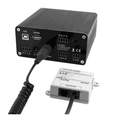
•Command Station LZ100
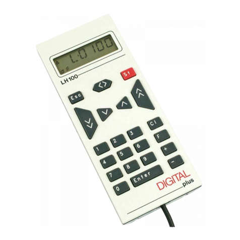
•Hand Held Controller LH100
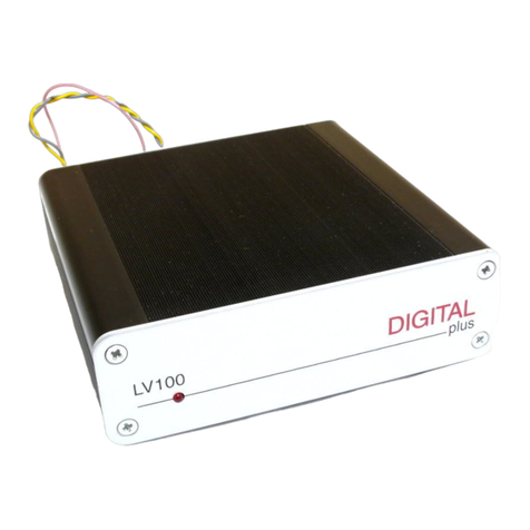
•Power Station LV100
•Locomotive equipped with a DIGITAL plus locomotive
decoder, or with another NMRA-DCC compatible locomotive
decoder (or an Arnold Digital or Märklin Digital= decoder)
•Transformer providing 16 volt AC and 50VA output
The DIGITAL plus units have removable multi-pin connectors
with screw terminals, to make connecting wires easy. Wire
Command Station LZ100 and Power Station LV100 together as
shown in Figure 1.Terminals Uand Von Command Station and
Power Station are the connection points for the transformer.
Connect terminals C, Dand Eon the Command Station with the
corresponding terminals on the Power Station.
Terminals Jand Kon the Power Station are for the connection
to the track (See Figure 2and 3).
Plug the connector of the Hand Held Controller LH100 into the
round 5-pin DIN terminal on the back of LZ100, marked “XBUS.”
Figure 1: Connecting LZ100 to Power Station LV100

Command Station LZ100 3
DIGITAL plus
Figure 2: Connecting to 2-Rail Figure 3: Connecting to 3-Rail
After connecting all the units, plug the transformer into a power
outlet. The display of the Hand Held Controller will briefly show
“LH100”, then it will display the address of the most recently
used locomotive, along with its data. On first use, the display will
show locomotive address 3 (factory set).
If your digital locomotive has another address, then press “Cl”
key on the Hand Held Controller. Next enter the desired
locomotive address on the keypad and verify it by pressing the
“Enter” key.
Now you can control the speed of your digital locomotive with the
following keys:
If you want to change your locomotive’s direction of travel, first
set the speed to step 0, then press the hexagonal key. The new
direction will be shown in the display.
With the “0” key you can turn the locomotive headlights on and
off (if connected). See your LH100 manual for more details.

4Command Station LZ100
DIGITAL plus
System design of DIGITAL plus
DIGITAL plus is a digital multi-train control system for all model
railroad scales. It was developed in close cooperation with model
railroaders. The basis for its development was the digital
systems Arnold Digital and Märklin Digital=, also developed by
Lenz Elektronik GmbH. Figure 4shows the simple and clear
system design of DIGITAL plus.
DIGITAL plus is compatible with NMRA-DCC systems and their
locomotive and accessory decoders. If you have older Arnold
Digital and Märklin Digital=, you can use locomotive decoders
and accessory decoders from these systems with DIGITAL plus.
Also,if you have devices from these systems (control 80,
keyboard, etc), then you can continue to use them with the
original central unit= and the Translation Module LC100 together
with DIGITAL plus.
Figure 4: DIGITAL plus System Overview
If you encounter compatibility problems with components you
already have, please contact us. We will do our best to resolve
such problems.

Command Station LZ100 5
DIGITAL plus
The capabilities of DIGITAL plus are to a large extent
determined by a program running inside the unit, the software.
The advantage of this approach is that new functions can be
adopted simply by changing the software. It is not necessary to
purchase new units. This way it is easier to implement
suggestions for improvements from model railroaders.
Command Station LZ100
The core of the system is Command Station LZ100. It
coordinates the input devices (Hand Held Controller LH100, etc.)
and is also responsible for data processing. Information is
exchanged between Command Station and input devices via a
4-wire cable, the XBUS. The Command Station generates the
control signals for Power Station LV100, which combines them
with the necessary power and sends them to locomotive and
accessory decoders.
Therefore,the Command Station has no boosted output to
connect to tracks. Accordingly it only needs a small transformer
(15VA), which could be one you already have from a starter set.
If you use a more powerful transformer, you can connect the
Command Station and the Power Station to the same
transformer.
Connecting the Command Station
Command Station LZ100 is connected to the AC output of the
transformer with 2 wires at terminals Uand V(see Figure 5). If
you use the digital transformers 6002 (Märklin) or 86002
(Arnold), you use their yellow and brown terminals.
Connect the programming track to terminals Pand Q. This track
must be completely isolated from the rest of the layout.
At terminals Cand Dthe data signal needed by the Power
Station is available. These terminals are connected with the
corresponding terminals on the Power Station with a twisted pair
wire (see Figure 5).
You can easily make a twisted pair wire from two normal single
wires that you twist together.
6Command Station LZ100
DIGITAL plus
Figure 5: Complete Connections of Command Station and Power Station
If terminal Eon the Command Station is connected to terminal E
on the Power Station, the Power Station is able to provide
feedback about overloads. The Command Station will then turn
off all other Power Stations and send the corresponding
information to Hand Held Controllers and other input devices.
The feedback bus is connected at terminals Rand S. Via this
wire, which also must be a twisted pair, the Command Station
asks for the state of for example turnouts or track occupancy
detectors. For this purpose, feedback units are connected to this
(Accessory Decoder with Feedback LS100 or Feedback Encoder
LR100). For more details on connecting these units, please refer
to the respective manuals.
If the Command Station is correctly installed and wired, and the
supply power of the transformer switched on, the LED on the
front of the Command Station lights up. If the LED flashes after
the power up, then there is a wiring problem on the XBUS.
Data transfer between Command Station and
input devices
The connecting wires from Command Station LZ100 to the input
units, for instance Hand Held Controller LH100, or the Interface,
are referred to as XBUS.

Command Station LZ100 7
DIGITAL plus
Figure 6: When wiring the X-BUS, wires must not be
allowed to branch or loop
Via this bus, the Command Station and connected devices
exchange information. A maximum of 30 devices are allowed on
the XBUS. Each of the connected units has its own address, so
that data exchange is problem-free.
Directions for how to change the address of Hand Held
Controller LH100 or another input device on the XBUS are found
in the corresponding manuals.
The XBUS can be connected to the Command Station via either
a 5-pin DIN connector or terminals L, M, Aand B. You can
connect the first Hand Held Controller directly to the 5-pin DIN
connector on Command Station LZ100.
If you want to connect additional Hand Held Controller LH100 (or
other input devices) to Command Station LZ100, then you use
terminals L, M, Aand B. Via the wires at terminals Aand B, the
units exchange data with the Command Station. Via the wires at
terminals L(plus) and M(minus) the units are supplied with
power.
Figure 7: Connecting Panel 21150 Figure 8: Pin Assignments from solder
side
From these terminals you run wires (XBUS wire) to the
connecting panels (see Figure 7, catalog number 21150). You
can also solder the wires yourself to a female 5-pin DIN
connector. These connectors are readily available in electronics
stores. The pin assignments of the 5-pin DIN connector are
shown in Figure 8.

8Command Station LZ100
DIGITAL plus
Make sure that you do not accidentally reverse the polarity
at terminals L and M by switching wires. This could cause
damage to connected input devices.
The XBUS wire must be installed so that the line starts at the
Command Station and ends somewhere on your layout. (Daisy
chained from Command Station via intermediate input locations
to the last input location.) Between the start and end you may
insert connecting panels or 5-pin DIN connectors anywhere. You
may not route the wire in a hub-spoke pattern or as a closed
loop. Under all circumstances you must ensure that the wires
that are connected to terminals Aand Bare twisted. All wires
should have a cross section of at least 0.25 square millimeter.
The length must not exceed 100 meter (327 feet).
The ends of the data bus must be connected (terminated) with a
resistor (included with the Command Station). The value of the
resistor is 120 Ohm.
Figure 9: Terminating the X-BUS with a 120 Ohm Resistor
Hüttenbergstraße 29
35398 Gießen, Germany
Hotline: 06403 900 133
Fax: 06403 5332
http://www.lenz.com
Lenz Agency of North America
PO Box 143
Chelmsford, MA 01824
ph/fax: 978 250 1494
This equipment complies with Part 15 of FCC Rules. Operation is subject to the
following two conditions: (1) this device may not cause harmful interference, and
(2) this device must accept any interference received, including interference that
may cause undesired operation.
© 1996 Lenz GmbH, All Rights Reserved
Other manuals for DIGITAL plus LZ100
1
Table of contents
Other Lenz Controllers manuals

Lenz
Lenz Digital Plus LH100 Manual

Lenz
Lenz PositionServo 940 User manual

Lenz
Lenz digital plus lh01 Manual

Lenz
Lenz DIGITAL plus LZ100 Technical manual

Lenz
Lenz Digital plux LH101-R User manual

Lenz
Lenz Digital plus LH101 User manual

Lenz
Lenz Digital plus Set-01 User manual

Lenz
Lenz Digital plus LH101 User manual

Lenz
Lenz Digital plus LH101 User manual