metalligence SLE111GW User manual

i
SLE111GW
Application Gateway
User Manual
Dec. 2013

ii
Table of Contents
1 INTRODUCTION..........................................................................................................1
F
EATURES
..........................................................................................................................1
P
ACKAGE
C
ONTENTS
..........................................................................................................1
2 HARDWARE ................................................................................................................2
F
RONT
P
ANEL
.....................................................................................................................2
R
EAR
P
ANEL
......................................................................................................................3
3 CONNECTION..............................................................................................................4
H
ARD
C
ONNECTION
............................................................................................................4
S
YSTEM
L
OGIN
...................................................................................................................4
APPENDIX A. HARDWARE SPECIFICATIONS .................................................................5
APPENDIX B. COMPLIANCES ..........................................................................................6

1
1 Introduction
The SLE111 is an integrated gateway for power and sensors data collection and
transmission.
Features
Offering the total visibility and detail analysis data on the energy consumption status with
clear and intuitive reports
Offering automatic control on office equipments, appliances and devices by both user
remote control and automatic scheduler settings
Offering monitoring policy to manage equipments, appliances, and devices more
efficiently, while providing electrical usage safety
Package Contents
The Gateway package includes:
Gateway x 1
AC Adapter x 1
User Manual x 1
Inform your dealer if there are any incorrect, missing or damaged parts. If possible, retain
the carton, including the original packing materials. Use them again to repack the product
in case there is a need to return it.
2
2 Hardware
The Gateway connects to the broadband modem (Cable/DSL) using its RJ-45 WAN port. It
connects directly to your PC or to a local area network using its RJ-45 Fast Ethernet LAN
ports.
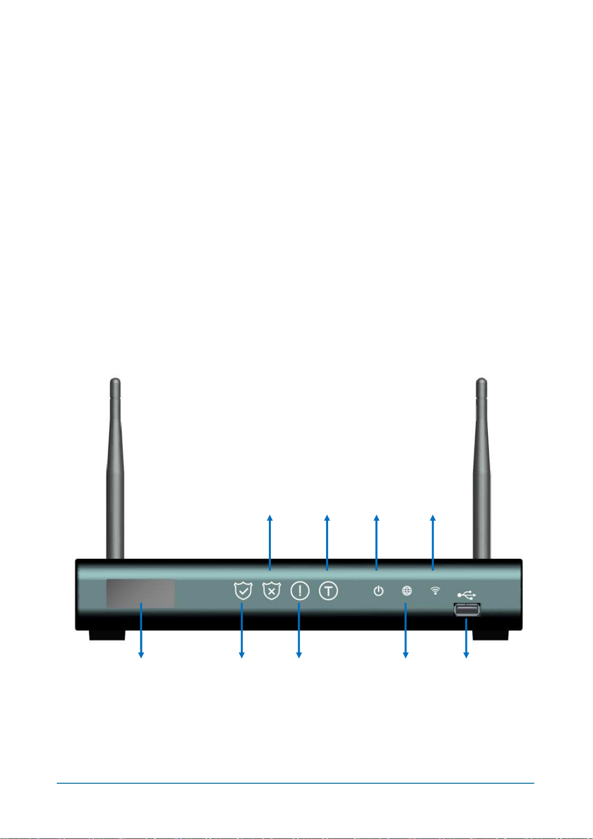
The Gateway includes an LED display on the front panel for system information display,
and LEDs for system status and touch buttons for system modes changing. It simplifies
installation and system troubleshooting.
Front Panel
USB Port LED Display Panel Alarm
Button
Panic
Button
Disalarm
Button
Reserved
Power
LED
Wireless
LED
Internet
LED

3
Rear Panel
Name
Description
DC 12V Connecter for a power adapter. This Gateway requires a
adapter of 12VDC/ 1.5A~2A.
Power Switch
Switch to power on/off the Gateway.
Ethernet
Port 0
For engineer troubleshooting purpose only.
Port 1and 2
For connect to a broadband router to build Internet
connection.
or
For connect to Ethernet network devices, such as a PC,
hub, switch or router for local access.
DC Jack Power Switch
Ethernet Port 0-2
Antennas
4
3 Connection
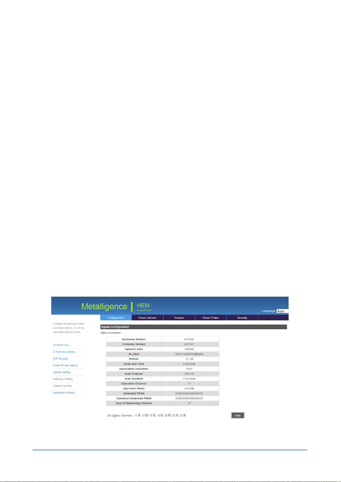
The Gateway offers a user-friendly web-based management interface for the configuration
of all the unit’s features.Any PC directly attached to the unit can access the management
interface using a web browser, such as Internet Explorer, Firefox, Chrome, and etc.
Hard Connection
1. Connect your broadband modem (Cable/DSL) to Ethernet port 1 on the Gateway.
2. Connect the Ethernet port of your PC to Ethernet port 2 on the Gateway.
3. Connect the power supply to the Gateway and power on it.
System Login
You can access the Web Application from any computer connected to the Gateway via the
Ethernet port.
1. Open your web browser. Type the default IP address of the Gateway
http://10.10.10.10 and press Enter.
2. A login screen displays. Enter user name as mtladmin and password as
@mtladmin@ (case sensitive). Click OK.

5
Appendix A. Hardware Specifications
ZigBee Pro standard IEEE 802.15.4 compliant, 2.4GHz
Ethernet: RJ-45 10BaseT/100BaseTX x 3
USB 2.0 x 2, 1 @internal & 1 @front
Antenna x 2
LED Panel
LED Indicator x 3
Function Touch Button x4
Power Switch Button
Power Supply: 12V DC external power adapter
Input: 100 ~ 240VAC
Output: 12V DC, 1.5 ~ 2A
Transmission Range: 50 m (line of sight)
Dimension: 250(L) x 156(W) x 40(H) mm (not include antennas)
Weight: 700 g
Operating Temperature: -10 ~ 50°C
Operating Humidity: 95 % RH

6
Appendix B. Compliances
FCC Interference Statement
This equipment has been tested and found to comply with the limits for a Class B digital
device pursuant to Part 15 of the FCC Rules. These limits are designed to provide
reasonable protection against radio interference in a commercial environment. This
equipment can generate, use and radiate radio frequency energy and, if not installed and
used in accordance with the instructions in this manual, may cause harmful interference to
radio communications. Operation of this equipment in a residential area is likely to cause
interference, in which case the user, at his own expense, will be required to take whatever
measures are necessary to correct the interference. If this equipment does cause harmful
interference to radio or television reception, which can be determined by turning the
equipment off and on, the user is encouraged to try to correct the interference by one of the
following measures:
•Reorient or relocate the receiving antenna.
•Increase the separation between the equipment and receiver.
•Connect the equipment into an outlet on a circuit different from that to which the
receiver is connected.
•Consult the dealer or an experienced radio/TV technician for help.
The device complies with Part 15 of the FCC Rules. Operation is subject to the following
two conditions: (1) This device may not cause harmful interference, and (2) this device
must accept any interference received, including interference that may cause undesired
operation.
FCC Caution: Any changes or modifications not expressly approved by the party
responsible for compliance could void the user’s authority to operate this equipment.

7
IMPORTANT NOTE:
FCC RADIATION EXPOSURE STATEMENT
This equipment complies with FCC radiation exposure limits set forth for an uncontrolled
environment. This equipment should be installed and operated with minimum distance
20cm between the radiator & your body.
This transmitter must not be co-located or operating in conjunction with any other antenna
or transmitter.
IEEE 802.11b, 802.11g or 802.11n operation of this product in the U.S.A. is
firmware-limited to channels 1 through 11.
根據
根據根據
根據 NCC 低功率電波輻射性電機管理辦法
低功率電波輻射性電機管理辦法低功率電波輻射性電機管理辦法
低功率電波輻射性電機管理辦法
第十二條:
經型式認證合格之低功率射頻電機,非經許可,公司、商號或使用者均不得擅自變更頻率、
加大功率或變更原設計之特性及功能。
第十四條:
低功率射頻電機之使用不得影響飛航安全及干擾合法通信;經發現有干擾現象時,應立即停
用,並改善至無干擾時方得繼續使用。前項合法通信,指依電信法規定作業之無線電通信。
低功率射頻電機須忍受合法通信或工業、科學及醫療用電波輻射性電機設備之干擾。
This symbol was placed in accordance with the European Union Directive
2002/96 on the Waste Electrical and Electronic Equipment (the WEEE Directive).
If disposed of within the European Union, this product should be treated and
recycled in accordance with the laws of your jurisdiction implementing the WEEE
Directive.
Table of contents
Popular Gateway manuals by other brands


Encom
Encom Harmony IP I/O8 user manual

Smart Friends
Smart Friends Box installation instructions

Ingics
Ingics iGS01S user manual

ZyXEL Communications
ZyXEL Communications ZyWALL USG 100 Series Specifications

Moxa Technologies
Moxa Technologies MGate 5102-PBM-PN Quick installation guide

ABB
ABB Ekip E-Hub manual