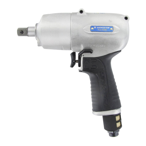
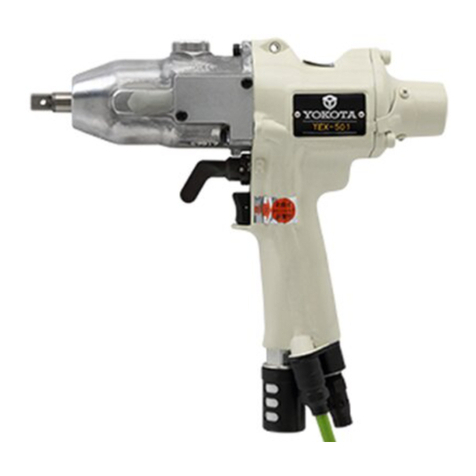
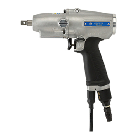
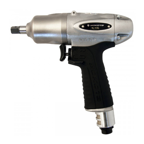
Yokota YZ-TH600 User manual

76-QD0460EN-01Y00-00
1
Battery Shut-Off Wrenches
YZ-TH600
YZ-TH800
YZ-TH900
YZ-TH950
Instruction Manual
Thank you for purchasing YOKOTA products.
Before use, please read this Instruction Manual carefully
and use the product properly after fully understanding the Manual.
Please be sure to keep this Instruction Manual.
YOKOTA INDUSTRIAL CO., LTD
Head Office/Factory 5-55 Nishiiwata 3-chome, Higashiosaka City, 578-0947 Osaka, Japan
TEL.: +81-6-6788-1381 FAX. +81-6-6781-4519
http://www.yokota-kogyo.co.jp

76-QD0460EN-01Y00-00
2
Table of contents
■1.SAFETY CARE ................................................................................................................................................ 3
■2.GLOSSARY ...................................................................................................................................................... 9
■3.OVERVIEW OF THE PRODUCT .......................... エラー! ブックマークが定義されていません。
■4.SPECIFICATION ..................................................... エラー! ブックマークが定義されていません。
■5.EACH PART DESCRIPTION ...................................................................................................................... 13
■6.PREPARATION BEFORE USE................................................................................................................... 16
■7.PAIRING.......................................................................................................................................................... 17
■8.USE.................................................................................................................................................................. 19
■9.PERFORMANCE INSPECTION MODE ..................................................................................................... 29
■10.BUZZER SOUNDS AND LED LIGHTING PATTERNS ...................................................................... 30
■11.ACCESSORIES ......................................................................................................................................... 32
■12.MAINTENANCE AND INSPECTION ..................................................................................................... 32
■13.CAUTION ON DISPOSAL....................................................................................................................... 32
■14.TROUBLESHOOTING.............................................................................................................................. 33

76-QD0460EN-01Y00-00
3
■1.Safety Care
Warning:Please be sure to thoroughly read this Instruction Manual and fully understand the
Instruction to use correctly, before installation, operation, maintenance and inspection.
■In this Instruction Manual, safety precautions prefix either of the following safety alert pictograms.
All are important items relating to safety and must be observed.
Warning・・・Cases where mishandling induces a potentially hazardous situation, which, if not
avoided, could result in a death or serious personal inquiry.
Caution・・・Cases where mishandling induces a potentially hazardous situation, which, if not
avoided, may result in minor or moderate personal injury or property damage.
※Notes: Even items described in “Caution”may lead to serious consequences depending on
circumstances.
■Retain this Instruction Manual in a place where it is always available for anyone who needs to use it
and read repeatedly.
■In cases where you lost this Instruction Manual or the warning label affixed to the product or made it
dirty, immediately contact us or your YOKOTA distributor to obtain the Manual or the warning
label, and then properly retain the Manual or replace the warning label.
■In cases where you transfer or rent this product, be sure to attach this Instruction Manual to it.
If you have any questions on the product or the contents in this manual, please contact us or our
distributor where you purchased the product.
Warning ■Please be sure to thoroughly read this Instruction Manual and fully understand
the instruction to use correctly, before using this product.

76-QD0460EN-01Y00-00
4
●Installation, Environment
Warning
・This product is for the indoor exclusive use. Do not use it in rain, in a damp place and a wet place.
・Dark or messy workplace could result in accidents. To avoid that, pay careful attention to lighting and
make efforts to keep the workplace clean and tidy.
・To protect yourself, wear personal protective equipment such as a hard hat(helmet), safety glasses,
safety shoes. And depending on work environment, wear earplugs, a dust mask etc.
・Dress properly. When working, do not wear loose clothes or jewelry such as necklace. If your hairs are
long, bundle them with rubber ring to avoid contact with the tool and wear a protective cover such as
cap. Otherwise, it may cause injury.
・Do not use this product in a place likely to be exposed to water, direct sunlight, much dust, heat, oil,
or moving parts of industrial equipment. Otherwise, it may cause fire, electric shock, or accident.
・Do not operate the tool in explosive atmospheres, such as in the presence of flammable liquids, gases
or dusts. There is a fear of fire. Other than that, do not use in a place with electrical and mechanical
harmful atmosphere.
・Use it away from things that generate large noise (welding machine · DC motor with brush etc.).
・Do not place inflammable materials nearby. There is a fear of fire.
・Do not make the foreign object such as metal pieces, invaded to the product. There is a fear of fire.
・Use the battery charger at rated supply voltage (AC 100-240 V).
Do not use DC power supply, engine generator, or power transformer. Failure to do so may result in
heat generation and fire.
・Be sure to fully insert the power plug of the battery charger. Failure to do so may result in electric shock
or fire due to heat generation.
・If you do not use the product, unplug the battery charger.
Wipe out dust or stain accumulated on the power plug or receptacle with a dry cloth.
Failure to do so may result in electric shock or fire.
・Do not insert or remove the power plug of the battery charger from the receptacle with wet hand. There
is a fear of electric shock.
・Charge the battery pack in well-ventilated place. While charging, do not cover the ventilation openings
on the battery pack and battery charger with cloth. Doing so may result in rupture or fire.
・In cold location or before starting the work in winter season, use fully charged battery pack.
If the battery pack is at low level, it may not be able to be used due to its protective function.
・Place the charger in a place of 0 to 40 ° C. Do not charge the battery pack at less than 0℃
or more than 40℃. Doing so may result in rupture or fire.
・If this product is suspended by balancer etc., mount YOKOTA-specified hanger to the product.
Use the threaded holes for mounting hanger only for mounting YOKOTA-specified parts.

76-QD0460EN-01Y00-00
5
●Operation, Driving
Warning
・To protect yourself, wear personal protective equipment such as a hard hat(helmet), safety glasses,
safety shoes. And depending on work environment, wear earplugs, a dust mask etc.
・Dress properly. When working, do not wear loose clothes or jewelry such as necklace. If your hairs are
long, bundle them with rubber ring to avoid contact with the tool and wear a protective cover such as
cap. Otherwise, it may cause injury.
・Use the power tool for tightening of screws. Use for other purposes may cause accident.
・Avoid the use of the power tool by persons inexperienced for handling. Otherwise, it may
result in injury and/or accident.
・Use the tool within its capacity. Unreasonable use of the tool in overload could result in the damage or
failure of the tool.
・Use the tool with proper tightening capability for the object to be tightened. If the capability is too big for
the object, the object or work piece may be broken or damaged and the broken pieces may cause
injury.
・Keep the tool away from the moving parts of plant facility. Otherwise, the tool may be entangled or
pinched and it may be damaged.
・Handle the power tool carefully. Abuse may cause accident and/or malfunction. Do not give impacts on
it by throwing or dropping it.
・Do not use a socket with much wobble.
・After installation of the attachment, pull it lightly and make sure that it does not come off.
Note that unsecure installation may cause damage on the attachment and/or early malfunction of the
product as well as accidents.
・If attachments for hand tools are used, there is a risk of breakage which may cause the
accident such as scattering of fragments. Therefore be sure to use attachments for power tools.
・Use socket stoppers specified by Yokota or socket makers. Do not use wire, a nail and
others as a substitute for a socket stopper, which can cause serious accidents.
・Fix the work piece (object to be tightened) securely. If the fixing is insufficient, the work piece (object to
be tightened) may be dispersed and it may cause injury.
・NEVER bring your hand or a cloth and so on to the moving part of the tool.
・Before attachment of the battery pack to the tool, make sure that the tools such as pins used
for capability adjustment are removed and the throttle lever is in OFF position. Otherwise, the tool
may accidentally operate and it may result in injury.
・Be sure to check the direction of reverse lever of the power tool before operation.
Be sure to switch the rotational direction while the power tool stops.
・When running the tool at no load, be sure that the tip tool (like socket, bit and so on) was removed without
fail and be careful around the surroundings. The operation at no load for a long time will result in the part
seizure, early wear and heat generation of the motor.

76-QD0460EN-01Y00-00
6
・Engage the tip tool (like socket, bit and so on) securely to the fastener before pulling the throttle lever.
・Pull the throttle lever of the tool slowly to start. Sudden start may cause accident or malfunction.
・Working in unusual positions is dangerous. Hold the tool securely and carry out working in stable
posture, preparing for accidental movement at the same time.
・Be careful about burn injury. During use and immediately right after tightening, metal parts, tip tool, bolts
and nuts may be hot.
・Do not touch metal parts, tip tool, bolts and nuts immediately right after tightening.
Also, do not touch the exhaust port of the tool during use. There is a fear of burn injury.
・Do not make the foreign object such as metal pieces, invaded to the product. There is fear of fire.
・Do not stick the pin, bar and so on into the inlet or exhaust of the cooling fan nor plug the hole.
・Do not remove the parts from the tool. If you use such tool as the mounted parts or screws removed,
it may result in accident.
・Do not pinch the power supply cord of the battery charger in the object to be tightened or do not
contact the cord with rotating parts. Otherwise, it may be damaged and result in accident.
・Use the exclusive battery pack and battery charger only.
・Do not disassemble or modify the battery pack and battery charger.
Doing so may result in heat generation, fire, electric shock, or injury.
・Do not throw the battery pack into fire or heat it.
Doing so may result in rupture or release of hazardous substances.
・Do not drive a nail or give an impact such as fall on the battery pack or battery charger.
Doing so may result in heat generation, fire, electric shock, and/or injury.
・Do not short-circuit the terminals of the battery pack.
Do not carry or store the battery pack with metal object such as nail. Doing so may result in
smoking, ignition, or rupture.
・If the battery pack gets hot during its use, stop using it immediately and after detaching the battery
pack from the tool, contact our distributor or sales representative where you have purchased.
・If the battery pack leaks, stop using it and contact our distributor or sales representative where you
have purchased.
・If the electrolyte of the battery gets in your eyes, do not pass your hand over your eyes, but flush them
with a plenty of clean water and seek medical attention. Failure to do so may result in loss of vision.
・If the electrolyte of the battery comes in contact with body part or clothes, rinse with a plenty of clean
water and seek medical attention. Failure to do so may result in dermal inflammation or injury.
・Noise might be regulated under laws and regulations of the country or regions where the product is used.
The tool must be used at noise levels below those prescribed by them, not to trouble the
surroundings. Install sound insulation walls, depending on the necessity.
If noise levels at the operator’s position exceed 85dB (A), be sure to use earplugs.
Even if noise levels are not more than 85dB (A), it is recommended to use earplugs.
・When the tool receives damage such as breakage or if you feel uneasiness during the use, stop using
the tool immediately and after removing the battery pack, ask repair or inspection to YOKOTA or
76-QD0460EN-01Y00-00
7
YOKOTA-authorized or designated servicing factory via our distributor or sales representative.
If any accident or problem occurs due to the customer’s intended action such as disassembly of this
product, we shall not be liable for such trouble.
・Before doing the following actions, remove the battery pack from the tool. Otherwise, it may accidentally
operate and result in injury.
・Storage or repair of the tool
・Replacement of socket and bit
・Adjusting the relief valve
・Other cases in which the operation of the tool may result in danger.
・Remove the tool's battery pack when not using it.
Caution
・Operate at the correct scaffold and environment. Work in an unreasonable posture is very dangerous.
・Do not use the tool when you are tired or under influence of drugs, alcohol or medication.
A moment of inattention during the use of tool may result in serious personal injury.
・When plugging and unplugging the setting device, remove the battery pack. Otherwise, it may
result in the breakdown.
・When plugging and unplugging the setting device, treat the connector carefully.
Otherwise, it may result in the breakdown.
●Maintenance, Inspection, and Repair
Warning
・Before operation, be sure to carry out the following checking. If you fail to do it, it may cause not only
degradation of performance or trouble but also danger. Do not use when there is abnormality.
・No damage on the tool body
・No problem on operation of throttle lever or reverse lever
・No loosening or damage of screws for the tool
・No abrasion or damage on the tip tool, etc.
・Normal room/play or wobbling for connection between the tool and the tip tool or the
connection between the tool and battery pack
・Confirm the torque periodically by the torque wrench after tightening the bolt, nut and so on.
Confirm the retightening torque value and the output torque value in daily inspection.
・When using hanger, do the following inspection periodically:
・No damage of hooking parts such as balancer, and correct mounting condition.
・No damage or abnormality on the hanger of the tool ,
・Remove metal objects (clock, ring etc) before maintenance, inspection and repair. There is a danger of
electric shock or injury.
・Only qualified service person is allowed to do maintenance and repair the tool. Repair or maintenance
performed by non-qualified person or qualified person’s work beyond the qualification range may result

76-QD0460EN-01Y00-00
8
in serious personal injury of the user.
・NEVER make any modification to the tool. Doing so could result in accidents. In addition,
never use the spare part other than the genuine one.
・Do not hold the power supply cord for battery charger for carrying or pull the cord to unplug it. In addition,
be careful to avoid stepping on or being caught by the cord, and/or damage by excessive force. Damage
of the power supply cord may result in accident.
・If the tool operates for approximately half of work rate with fully charged battery pack, it means the expiry
of its operating life. Buy a new battery pack.
・If the tool is not used for long time, fully charge the battery pack before storage.
Even during storage, fully charge the battery pack more than once within one year of last charge.
Otherwise, over-discharge of the battery pack may prevent it from charging.
・Do not store the battery pack in a place reaching over 50℃. Doing so may cause deterioration of the
battery pack and result in smoking or fire.
・Do not short-circuit the terminals of the battery pack. Do not carry or store the battery pack with metal
object such as nail. Doing so may result in smoking, ignition, or rupture.
・Attach an anti-short-circuit cap after the battery pack is removed from the tool or the battery charger or
when the tool is not used. Failure to do so may result in short circuit of the terminals of the battery pack
and fire.
・Wipe out the dirt on the housing of the tool by using the dry and soft cloth.
Do not use the chlorinated solvent, gasoline, thinner and the like, which works to melt the plastic.
・Store the product in the dry area, where children or untrained person can not get access to.
●Disposal
Caution
・Dispose of it according to the method of sorting, laws and regulations, in the used area.
・Lithium-ion battery used in this battery pack is recyclable and valuable resource.
If it is no longer used, bring it to our distributor, etc. where you have purchased.
●Others
Caution
・Keep anyone, particularly children, other than those involved in the work away from the work
site. Not doing so could induce a hazardous situation.
・Do not touch the oil plug of the tool except repairing. It causes early oil leakage.
・Using a tool which has been in storage for more than 6 months may cause oil leakage because of damage
to the seal part on the impulse mechanism. We will inspect the tool which has been in storage for more
than 6 months.
・When using in cold place or in winter season, warming up for the tool is required.
Run the tool for about 0.5 to 1 second several times by loading the main shaft. If the warming up is not
carried out, generating pulses may not be stable.

76-QD0460EN-01Y00-00
9
■2.Glossary
(1) Value
A value at which the tool will shutoff once it reaches during rundown
(2) Tightening Value
The result value of a rundown
(3) Tightening Pulse No.
Number of pulses after reaching the display start value until shut-off.
(4) Display Start Value
Threshold value to judge OK or NG. At less than this value, no judgement is made.
(5) Switch Value
A value of switching point of motor speed from MID to HIGH rpm.
(6) Cut Value
The value at which the tool will automatically shut off during rundown
(7) Max Value
Maximum value to judge OK or NG。
(8) LOW Speed:
Free speed when the throttle lever of the tool is pulled slightly to the first step (at right/left rotation)
(9) MID. Speed
Free speed when the throttle lever of the tool is pulled to full. (only at right rotation)
※In case of reverse rotation, this setting is not valid. (Valid for low and high speed only).
(10) HIGH Speed:
Free speed after the Middle to High switch value is achieved. (at right rotation)
Free speed when the throttle lever of the tool is pulled to full. (at left rotation)
(11) MIN Pulse
Minimum pulse number for tightening to judge OK or NG.
(12) MAX Pulse
Maximum pulse number for tightening to judge OK or NG.
(13) Average Number
The arithmetic average from the preset number of pulses.
(14) Slow Error Pulses
The number of pulses in excess of the preset number (70 fixed) of pulses, including those less than
display start value, to judge.
(15) Value Judgement before average
Value over judgement as a base of the value before the arithmetic average

76-QD0460EN-01Y00-00
10
■3. Overview of The Product
This product is a shut-off tool which is used for bolt tightening, and will stop automatically according
to the tightening conditions. For tightening parameter setting, use the specially prepared
programing console PC-1 and cable CC-1 for the product.
By connecting YZ-TH to PC-1 via CC-1, the reference of rundown results and the test mode can be
possible in addition to the tightening parameter setting.
※[Setting device] described in this instruction manual, means programing console (PC-1) and
special cable (CC-1) in connection.
The battery pack should be detached from YZ-TH when connecting/disconnecting the
setting device to or from YZ-TH..
Connecting/disconnecting the setting device, in the state that YZ-TH runs, can be a cause
of failure.
When connecting and disconnecting the setting device to or from YZ-TH, treat the
connector carefully. Otherwise, it may result in the breakdown.
Close the shutter of the cable connecting port on the YZ-TH till it locks, when the setting
device is not connected.
Setting
Device
設定器
CC-1
YZ-TH
PC-1

76-QD0460EN-01Y00-00
11
■4. Specification
・TOOLS
Models
YZ-TH600A
YZ-TH600
YZ-TH800A
YZ-TH800
YZ-TH900
YZ-TH950
Bolt Capacity
M6
M6
M6~M8
M6~M8
M8~M10
M10
Torque adjustment range(※1)
5~18N・m
7~20N・m
10~30N・m
15~35N・m
30~50N・m
40~60N・m
Weight
incl. battery pack
1.4kg
1.4kg
1.5kg
1.5kg
1.6kg
1.65kg
excl. battery pack
1.0kg
1.0kg
1.1kg
1.1kg
1.2kg
1.25kg
Free speed setting range
HIGH : 1500~4800rpm
HIGH : 2000~4800rpm
MIDDLE : 1500~3000rpm
LOW : 1200~1500rpm
LOW : 1200~1500rpm
Total Length
161mm
161mm
166mm
166mm
173mm
173mm
Total Height including battery
pack
248mm
248mm
248mm
248mm
248mm
248mm
Spindle Offset
29.5mm
29.5mm
29.5mm
29.5mm
29.5mm
29.5mm
Sq. Drive/Bit size
Hex6.35
9.5mm
Hex6.35
9.5mm
9.5mm
9.5mm
Tightening Bolt No./min ※2
10pcs./min.
10pcs./min.
8pcs./min.
8pcs./min.
6pcs./min.
5pcs./min.
Tightening No./charge ※2
1300pcs
/charge
1300pcs
/charge
800pcs.
/charge
800pcs.
/charge
700pcs.
/charge
650pcs.
/charge
Noise
<EN62841-2-2>
Standard
Sound
pressure
level LPA
67dB
67dB
68dB
68dB
69dB
70dB
Uncertainty
KPA
3dB
3dB
3dB
3dB
3dB
3dB
Total values for three
measured axes of vibration
<EN62841-2-2 Standard> ※3
<2.5m/s2
<2.5m/s2
<2.5m/s2
<2.5m/s2
<2.5m/s2
<2.5m/s2
Ambient operating
temperature
0~40℃
Ambient operating humidity
35~80%RH((no condensation)
T
Exposure to vibration per day A(8)=a× ―[m/s2]
8
※1 Max. value of each adjustment range is at hard joint
※2 The value when our work is tightened at tightening
time of 0.5s and ambient temperature of 30 ℃. It
varies with the condition of the work or operating
environment and should be used as a guide.
※3 Triaxial combined vibration value was measured
according to the standard EN 62841-2-2 and no value
is measured in actual field. This value should be used
as a reference for the management of daily exposure
to vibration. Daily exposure to vibration A (8) is
exposure to vibration per day, and it can be
calculated from the following formula with triaxial
combined vibration value “a” [m/s2] of the tool and
the period of exposure to vibration per day “T” [h].
Spindle offset
Total Length
Total Height

76-QD0460EN-01Y00-00
12
・Battery Pack
Model
BPL-1820
Nominal voltage
18V
Rated capacity
2.0Ah
External dimensions
(W)76mm×(L)119mm×(H)45mm
Weight
0.41kg
Ambient operating temperature
0~40℃
・Battery Charger
Model
BC0075G
Rated input voltage
AC100~240V±10% 50/60Hz
Rated charging current
2A ※1
External dimensions
(W)200mm×(L)130mm×(H)84mm
Weight
0.84kg
Recharge time
80% charged : 60 min
Fully charged : 70 min
Ambient operating temperature
0~40℃
※1:At quick recharge
・Programing Console
Model
PC-1
External dimensions
(W)100mm×(H)185mm×(D)24mm
Weight
0.3kg
・Special Cable
Model
CC-1
Total Length
2.3m
Weight
0.2kg

76-QD0460EN-01Y00-00
13
■5. Each part description
・TOOLS
①Main Shaft
Rotates as the trigger is pulled.
②Throttle lever
Lever to start or stop the rotation of the main shaft of the tool.
③Reverse lever
Lever to switch the rotational direction (right/left) of the main shaft.
④Cooling fan (built-in)
Fan to cool motor section and pulse unit.
⑤Exhaust outlet of cooling fan
Exhaust outlet of cooling fan. Also used as insertion opening for
torque adjustment pin.
⑥LED Lamp
LED to inform the worker of tightening judgement, alarm and error.
⑦Cable connecting port
This is the port to connect the setting device. When connecting, open
the shutter. When not connecting, close the shutter until it is locked.
⑧Battery pack(For –Z models, to
be sold separately.)
Detachable battery pack for driving the tool.
⑨Identification Mark
YZ-TH series are yellow.
⑩Push Button
Gently push the button by TF pin for pairing.
※When pushing at the error occurrence, detailed information
displays on LED lamp.
●Explanation of Symbol mark
:Before use, read this Instruction Manual carefully and use the product properly after fully
understanding the Manual.
②
⑤
⑥
③
⑨
④
⑧
Open/Close of Shutter
Open
開
⑩
①
Close
閉
⑦

76-QD0460EN-01Y00-00
14
①
・Battery Pack(For –Z models, to be sold separately.)
①Terminal part
Terminal for connection with the tool
②Ventilation opening
Air intake for cooling the inside of the battery pack during charging
③Battery level indicator lamp
When PUSH button is pressed, the LED(s) light up and indicate the
level of the battery pack.
《Guide for battery level》
3 LEDs lighting: Not less than 75%
2 LEDs lighting: 30 to 75%
1 LED lighting: 5 to 30% (charge the battery pack as soon as
possible)
④Anti-short-circuit cap
Cap to prevent from short-circuit of terminal parts
⑤Release button
Button to release the battery pack from the tool
・Battery Charger(to be sold separately)
①Indicator lamp
LED lamp indicating the charging level
②Ventilation openings
Openings for cooling the battery pack.
③Power supply cord
Dedicated power supply cord for battery charger
③
④
①
②
③
②
⑤

76-QD0460EN-01Y00-00
15
・Programing Console PC-1(To be Sold Separately)
①Mounting hole
②Display screen
Displays tightening result, setting item and set value
③Function key
Switching of tightening screen, setting screen and or of display screen
④Numeric key
Enter the set value
⑤CAN key
Return to the previous screen
⑥ENT key
Determine items and input value
⑦Up, down, left and right key
Move the selection of setting items up and down
⑧PRC05 connector
Connector for connecting cable
・Special Cable CC-1(To be Sold Separately)
①PRC05 connector
Connector for connecting with programing console PC-1
②YZ-TH Connector
Connector for connecting with YZ-TH
①
②
②
④
③
①
⑤
⑥
⑦
⑧

76-QD0460EN-01Y00-00
16
■6.Preparation before use
Before use, read, especially 「●Installation, Environment」of Chapter 1 「■Safety Care」
carefully and use the product properly after fully understanding the Manual.
Since the battery pack you purchased is not fully charged, fully charge it before use.
6.1.Method of charging
①Connect the battery charger to the power supply cord, and insert the power plug into the
receptacle. The LED of the charger is still off.
②Insert the battery pack into the battery charger.
Slide the battery pack to the end along with the insertion slot of the battery charger.
When it is correctly installed, the LED lights in red and the charging starts.
※Depending on the temperature of battery pack, the cooling fan activates or stops.
While charging, operation of the cooling fan varies but it is not the malfunction.
When the charging is completed (fully charged), the LED lights in green.
③Remove the battery pack from the battery charger
④Remove the power plug of the battery charger from the receptacle.
6.2.Lightening pattern of indicator lamp of the battery charger
LED Display Condition LED
Charging Condition
Color
Lighting Condition
Off
Off
Condition of plugging in
Red
Lighting
Charge in process
Green
Blinking
Practical charge(80%)completed
Green
Lighting
Charge completed
Orange
Blinking
Charge standing-by (Temperature of
battery Pack is high/low.)
Red
Blinking
Charge impossible (Abnormality etc. of
battery pack)
6.3.Installation of the battery pack
Slide the battery pack along the insertion slot of the tool to the end and make sure that it does
not come off (it clicks when the battery pack is slid to the end).
6.4. Removal of the battery pack
While pressing the eject buttons on both sides of the battery pack, slide it to your side

76-QD0460EN-01Y00-00
17
■7.Pairing
The product can be possible to communicate the rundown data (tightening OK only) to the
receiver for pokayoke TW-800R series (hereinafter called “receiver”) made by Herutu Electronics
Corporation.
To make the communication effective, the pairing (initial connecting setting) between the tool and
receiver, is necessary.
7.1. Pairing Procedure
After putting on the power switch of receiver, proceed the pairing with the following procedure.
For the operational details of the receiver, refer to the instruction manual issued by Herutu
Electronics Corporation, attached with the receiver.
①Install the battery pack to the tool.
②Activate the tool by pulling the throttle lever once.
Be careful, since the main shaft of the tool rotates at the same time when the throttle lever is
pulled.
③By pressing the light switch for pairing, at the same time put on the power switch.
(Refer to the below)
・It turns to be in the pairing mode for 10 seconds
and the light switch for pairing is blinking.
・After a lapse of 10 seconds from the pairing
mode, the pairing mode automatically finishes
and the light switch for pairing stops blinking to
put out the light.
If the pairing is not successfully done during
that period, put off the power switch of the
receiver again and re-start the pairing
operation
④While the light switch for pairing of the receiver is blinking, do the pairing by pressing the push
button located on the backward of the tool with the flat bottom of TF pin 2x90. (Refer to the below.)
・At the same time when it is pressed, white LED
on the back of the tool lights. Hold pressing
until the buzzer beeps.
・At the same time when the long beep starts,
the white LED goes off and then, remove the
TF pin from the push button. “
Light switch
for pairing
Power Switch
TF Pin 2x90

76-QD0460EN-01Y00-00
18
・When pressing the push button for a long time for pairing, slowly remove the TF
pin from the push button right after the white LED goes off and the long beep starts.
Keep pressing can not enable the pairing.
・Do not remove the battery pack from the tool, during the pairing.
⑤When the pairing is successfully done, the light switch for pairing of receiver goes off and on the
tool side, the blue LED lights for 0.5 second together with buzzer beep sound.
When the pairing is failed, on the tool side the purple LED lights for 0.5 second together with
intermittent buzzer beep sound. Do the pairing procedure once again from the beginning.
Condition
Buzzer sound pattern
LED lighting pattern
When pairing is
successful
The buzzer beeps.
Blue lighting for 0.5 sec.
When pairing is failed
The buzzer beeps intermittently.
Purple lighting for 0.5 sec.
⑥After the pairing is successfully done, put off the power switch of the receiver once without fail and
put it on again. By doing so, the communication can be possible with the tool paired.
Even if the pairing is successfully done, the communication with the tool can not be possible,
unless the power switch of the receiver is turned OFF/ON.
⑦Others
・Even if the battery pack is removed and installed again after the completion of pairing, the pairing
status is maintained. Likewise, even if the power switch of the receiver is turned OFF/ON, the pairing
status is maintained.
・To release the pairing of the tool, do the pairing procedure at the status when the receiver is not in
the pairing mode. After it turns out to be the failure of the pairing (purple LED lighting), the pairing
will be released.

76-QD0460EN-01Y00-00
19
■8. Use
Before use, read, especially 「●Operation, Driving」of Chapter 1 「■Safety Care」carefully and
use the product properly after fully understanding the Manual.
8.1. Operation Mode
Stand alone
Using YZ-TH alone
Stand-by mode
This is the mode before pulling the throttle lever after installing the battery pack
or after 15 minutes from the last pull of the throttle lever.
Cooling fan and LED would be turned off.
Operation mode
When pulling the throttle lever at stand-by condition, it turns into operation
mode and the main shaft rotates, activating the cooling fan. During the
operation mode, LED lamp lights and the buzzer sounds at tightening
judgement. At the occurrence of alarm or error, LED lamp lights or blinks.
After 15 minutes from the last pull of the throttle lever, it goes into a Stand-by
mode.
Operation connecting with setting device
Using YZ-TH connecting with setting device
Setting Mode
When pulling the throttle lever after connecting the setting device and then,
installing the battery pack, setting mode starts. The cooling fan and LED lamp
do not activate. This mode can set tightening parameter, check the rundown
results, and run into test mode.
*Note: The tool does not run even when pulling the throttle lever at the setting
mode
Test Mode
By selecting the test mode from the setting mode, test mode starts.
At test mode, the main shaft rotates when pulling the throttle lever and
tightening can be possible. The tightening results display on the setting device.

76-QD0460EN-01Y00-00
20
8.2. Functions of throttle lever and reverse lever
Throttle lever
After inserting the battery pack and then pulling
the throttle lever, the main shaft rotates.
When pulling the throttle lever lightly, the rotation
speed sets to be [low] and when pulling it more,
it sets to be [middle]. After releasing the throttle
lever, rotational operation stops.
Reverse lever
It switches the rotational direction of the main
shaft. When pressing its R-side and pulling the
throttle lever, it rotates right and when its L-side,
it does left.
※*While the main shaft rotates, do not operate
the reverse lever.
8.3. Tightening Judgement (Correlation with judgement, value and pulses)
①After tightening, the tool judges whether the tightening results ( the value and pulses) are within
the setting range
②If the tightening results (value and pulses) are within the setting range, the tool judges OK.
③If the tightening results (value and pulses) are not within the setting range, the tool judges NG.
④Tightening NG details
・Value NG(less than cut value/more than cut value/value before average exceeded max value
・Pulse NG(less than min pulse/more than max pulse/slow err)
⑤Slow:Pulses exceed slow error pulses (70 fixed ) including those less than start value
※Value:A guide value at which the tool will shutoff once it reaches during rundown
Left
Right
Press L side:Left
Press R side:Right
R側
L側
Max. Value
Cut value
Value
Pulse
Max pulse
Min pulse
Display Start value
OK Over Pulse
Over Value
Under Value
Under Pulse
This manual suits for next models
3
Table of contents
Other Yokota Power Tools manuals

Yokota
Yokota YEX-901 User manual

Yokota
Yokota YEX-150S User manual

Yokota
Yokota YLT110EL User manual

Yokota
Yokota TKA800-C User manual

Yokota
Yokota TKA1110 User manual

Yokota
Yokota YX-180 User manual

Yokota
Yokota E-PDA-4 User manual

Yokota
Yokota YS-e600 User manual

Yokota
Yokota TKA700A-C User manual

Yokota
Yokota TKA60A User manual

Yokota
Yokota YLa90E User manual

Yokota
Yokota YX-180E User manual

Yokota
Yokota YLa110E User manual

Yokota
Yokota TKA70 User manual

Yokota
Yokota E-M700 User manual

Yokota
Yokota YLA60A-JQ User manual

Yokota
Yokota RRI-60X User manual

Yokota
Yokota TKA900 User manual

Yokota
Yokota YLa80E User manual

Yokota
Yokota YEX-100SA User manual