Metallkraft GS 18 User manual

GS 18
Operating Instructions
GS 18
Tapping Power Tool
GS 18

2GS 18 | Version 1.05
Imprint
Product identification
Tapping Power Tool Article number
GS 18 3860018
Manufacturer
Stürmer Maschinen GmbH
Dr.-Robert-Pfleger-Str. 26
D-96103 Hallstadt/Bamberg
Fax: 0049 (0) 951 96555 - 55
E-Mail: [email protected]
Internet: www.metalkraft.de
Indications regarding the operating instructions
Original instructions
Edition: 15.05.2019
Version: 1.05
Language: English
Author: FL/ES
Indications regarding the copyright
Copyright © 2019 Stürmer Maschinen GmbH, Hallstadt,
Germany.
The contents of these operating instructions are the sole
property of the company Stürmer.
Passing on as well as copying of this document, the use
and distribution of its content are prohibited if not explic-
itly permitted. Contraventions are liable to compensa-
tion.
Subject to technical modifications and error.
Content
1 Introduction .............................................................3
1.1 Copyright............................................................ 3
1.2 Customer service................................................ 3
1.3 Limitation of liability ............................................ 3
2 Intended use ............................................................3
3 Safety........................................................................4
3.1 Symbol explanation ............................................ 4
3.2 Obligations of the operating company............... 4
3.3 Requirements to staff.......................................... 5
3.4 Personal protective equipment........................... 5
3.5 Safety identifications on the Tapping Power Tool....6
3.6 Safety devices .................................................... 6
3.7 Special safety rules for tapping power tool ........ 6
3.8 Residual risks ..................................................... 6
4 Technical Data.........................................................6
4.1 Table................................................................... 6
4.2 Type plate........................................................... 7
5 Transport, package and storage............................7
5.1 Delivery and transport ........................................ 7
5.2 Packaging........................................................... 7
5.3 Storage ............................................................... 7
6 Description of the device........................................8
6.1 Illustration ........................................................... 8
7 Operation .................................................................9
7.1 Preparation ......................................................... 9
7.2 Electrical connection .......................................... 9
7.3 Drilling............................................................... 10
7.4 Depth stop ........................................................ 11
7.5 Safety clutch..................................................... 11
8 Cleaning, maintenance and service/repair .........11
8.1 Cleaning ........................................................... 11
8.2 Maintenance..................................................... 12
8.3 Servicing.......................................................... 12
9 Disposal, Recycling of old equipment ................13
9.1 Decommission................................................. 13
9.2 Disposal of electrical equipment..................... 13
9.3 Disposal of lubricants...................................... 13
10 Spare parts...........................................................13
10.1 Ordering spare parts..................................... 13
11 Spare part drawing.............................................15
12 Electrical wiring diagram....................................16
13 EC Declaration of conformity.............................17
Introduction
GS 18 | Version 1.05 3
1Introduction
You have made a good choice by purchasing the
METALLKRAFT tapping power tool.
Read the operating manual thoroughly before commissioning
the machine.
It gives you information about the proper commission-
ing, intended use and safe and efficient operation and
maintenance of your tapping power tool.
The operating manual is part of the tapping power tool
machine package. Always keep this operating manual
in the location where your tapping power tool machine is
being operated. All local accident prevention regula-
tions and general safety instructions for the operating
range of your tapping power tool machine must also be
complied with.
Illustrations in this operating manual serve the general
understanding and may deviate from the actual design.
1.1 Copyright
The contents of these instructions are copyright. They
may be used in conjunction with the operation of the
tapping power tool. Any application beyond those de-
scribed is not permitted without the written approval of
Stürmer GmbH.
For the protection of our products, we shall register
trademark, patent and design rights, as this is possible
in individual cases. We strongly oppose any infringe-
ment of our intellectual property.
1.2 Customer service
Please contact your dealer if you have questions con-
cerning your tapping power tool or if you need techni-
cal advice. They will help you with specialist information
and expert advice.
Germany:
Stürmer Maschinen GmbH
Dr.-Robert-Pfleger-Str. 26
D-96103 Hallstadt
Repair-service:
Fax: 0049 (0) 951 96555-111
E-Mail: service@stuermer-maschinen.de
Spare part orders:
Fax: 0049 (0) 951 96555-119
E-Mail: ersatzteile@stuermer-maschinen.de
We are always interested in valuable experience and
knowledge gained from using the application-which
then could be shared and be valuable to develop our
products even further.
1.3 Limitation of liability
All information and notes in these operating instructions
were summarised while taking applicable standards
and rules, the state-of-the-art technology and our long-
term knowledge and experiences into consideration.
In the following cases the manufacturer is not liable for
damages:
- Non-observance of the operating instructions,
- Inappropriate use
- Use of untrained staff,
- unauthorized modifications
- technical changes,
- Use of not allowed spare parts.
The actual scope of delivery may deviate from the ex-
planations and presentations described here in case of
special models, when using additional ordering options
or due to latest technical modifications.
The obligations agreed in the delivery contract, the gen-
eral terms and conditions as well as the delivery condi-
tions of the manufacturer and the legal regulations at the
time of the conclusion of the contract are applicable.
2 Intended use
The tap is used exclusively for producing right-hand
threads in continuous operation up to max. 14 mm (9/16
") diameter in steel and aluminum. Occasionally, threads
can be cut to 18mm. However, this is not possible in
continuous operation. Left-hand threads are not possi-
ble with this machine.
Proper use also includes compliance with all information
in this manual. Any use beyond the intended use or oth-
erwise is considered misuse.
WARNING!
Danger in case of misuse!
Misuse of the device can lead to dangerous situa-
tions.
- Only operate the machine in the power range spec-
ified in the technical data.
- Never bypass or override the safety devices.
- Only operate the machine in a technically perfect
condition.
4GS 18 | Version 1.05
Safety
Unauthorized modifications or changes to the tap can
invalidate the CE conformity of the tap and are prohib-
ited. The company Stürmer Maschinen GmbH assumes
no liability for design and technical changes to the tap.
The improper use of the tap and the disregard of the
safety regulations or the operating instructions exclude
liability of the manufacturer for resulting damage to per-
sons or objects and cause the warranty to expire!
3 Safety
This section provides an overview of all important safety
packages for the protection of operating personnel as
well as for safe and fault-free operation. Other task-
based safety notes are included in the paragraphs of
the individual phases of life.
3.1 Symbol explanation
Safety instructions
The safety notes in these operating instructions are
high-lighted by symbols. The safety notes are intro-
duced by signal words which express the concern of
the risk.
Tips and recommendations
It is necessary to observe the safety notes written in
these operating instructions in order to reduce the risk of
personal injuries and damages to property.
3.2 Obligations of the operating company
Operator
Operators are defined as the persons who operate the
machine for commercial or profit-based purposes or
provide the machine to third parties for use or applica-
tion and bear the legal product responsibility in terms of
the protection of users, staff or third parties during oper-
ation.
Obligations of the operating company:
If the machine is used for commercial purposes, the op-
erating company must comply with the legal working
safety regulations. Therefore, the safety notes in this op-
erating manual, as well as the safety, accident preven-
tion and environment protection regulations applying for
the area of application of the machine must be met. The
following applies in particular:
- The operating company must be informed about
the applying industrial safety regulations and fur-
ther analyse hazards resulting from the special
working conditions at the place of use the ma-
chine. She must implement these in form of oper-
ating manuals for the operation the machine.
- During the entire lifetime of the machine, the oper-
ating company must verify whether the operating
manuals prepared by her correspond to the cur-
rent status of the regulations, and must adapt
these if necessary.
- The operating company must unambiguously reg-
ulate and determine the responsibilities for instal-
lation, operation, troubleshooting, maintenance
and cleaning.
- The operating company must ensure that all per-
sons who work with the machine, have read and
understood this manual. Furthermore she must in-
struct the staff in regular intervals and inform them
about the hazards.
- The operator must provide the necessary protec-
tive equipment to the staff and order the use of the
necessary protective equipment in a binding way.
DANGER!
This combination of symbol and signal words indi-
cates an imminently dangerous situation which may
lead to death or severe injury if not avoided.
WARNING!
This combination of symbol and signal words indi-
cates a potentially dangerous situation which may
lead to death or severe injury if not avoided.
CAUTION!
This combination of symbol and signal words indi-
cates a potentially dangerous situation which may
lead to slight or minor injury if not avoided.
NOTE!
This combination of symbol and signal words indi-
cates a potentially dangerous situation which may
lead to material or environmental damage if not
avoided.
Tips and recommendations
This symbol highlights useful tips and recommenda-
tions as well as information for an efficient and trou-
ble-free operation.

Safety
GS 18 | Version 1.05 5
Furthermore the operating company is responsible to
keep the machine always in a technically flawless state.
Thus, the following applies:
- The operator must ensure that the maintenance in-
tervals described in this manual are kept.
- The operator must have all safety devices
checked regularly for their good working order
and their integrity.
3.3 Requirements to staff
Qualifications
The different tasks described in this manual represent
different requirements to the qualification of the persons
entrusted with these tasks.
Only persons reliable working procedures can be ex-
pected from, are allowed to perform all works. Persons
the responsiveness of which is affected by e. g. drugs,
alcohol or medication, are not allowed to work with the
machine.
The qualifications of the personnel for the different tasks
are mentioned below:
Operator:
The operator is instructed by the operating company
about the assigned tasks and possible risks in case of
improper behavior. Any tasks which need to be per-
formed beyond the operation in the standard mode
must only be performed by the operator if it is indicated
in these instructions and if the operating company ex-
pressively commissioned the operator.
Electrically qualified person:
Electrically qualified person is due to their professional
training, knowledge and experience as well as knowl-
edge of the relevant standards and regulations, in a po-
sition to carry out work on the electrical systems and to
independently recognize and avoid possible dangers.
Qualified personnel:
Due to their professional training, knowledge and expe-
rience as well as their knowledge of relevant regulations
the specialist staff is able to perform the assigned tasks
and to recognize and avoid any possible dangers them-
selves.
Manufacturer:
Certain works may only be performed by specialist per-
sonnel of the manufacturer. Other personnel is not au-
thorized to perform these works. Please contact our cus-
tomer service for the execution of all arising work.
3.4 Personal protective equipment
Personal protective equipment is intended to protect the
health and safety of persons at work. Staff must wear the
personal protective equipment indicated in individual
sections of these operating instructions when carrying
out the different tasks on the machine.
The personal protective equipment is described in the
following section:
WARNING!
Danger in case of insufficient qualification
of the staff!
Insufficiently qualified persons cannot estimate the
risks while using the vacuum cleaner and expose
themselves and others to the danger of severe or
lethal injuries.
- Have all works only performed by qualified per-
sons.
- Keep insufficiently qualified persons out of the
working area.
Ear protection
The Hearing protection protects ears from hearing
damage caused by noise.
Head protection
The industrial helmet protects the head against fall-
ing objects and knocking against fixed objects.
Face protection
The face shield protects the face from flying parts.
Protective gloves
The protective gloves serve to protect the hands
against sharp components as well as against fric-
tion, abrasions or deep injuries.
Safety boots
Safety boots protect the feet from being crushed,
falling parts and slipping over on slippery ground.

6GS 18 | Version 1.05
Technical Data
3.5 Safety identifications on the Tapping
Power Tool
The following safety identifications have been attached
to the tapping power tool (Fig. 1) which must be ob-
served:
Fig. 1: Safety identifications - 1 Mandatory signs: Read the operating
manual, Pull out the mains plug, wear eye protection, Wear ear
protection
The safety markings and instructions attached to the
tapping power tool must not be removed. Damaged or
missing safety markings can lead to malfunctions, per-
sonal injury and material damage. They have to be re-
placed immediately.
If the safety markings are not immediately recognizable
and comprehensible, the tapping power tool must be
taken out of operation until new safety markings have
been affixed.
3.6 Safety devices
3.7 Special safety rules for tapping power tool
- Do not connect other machines to the same mains
supply. This can cause voltage fluctuations.
- Do not use the machine overhead. It is highly rec-
ommended to use them at 45 ° to the horizontal.
Avoid larger angles. Working overhead is ex-
tremely dangerous and should be avoided.
- Do not work with blunt or damaged tools. This can
lead to overuse of the motor.
- Protect the engine. Make sure that no coolant, wa-
ter or other substances enter the motor.
- Metal shavings are usually very sharp-edged and
hot. Never touch them with your bare hands. Re-
move these with a magnetic chip collector or a
chip hook. Remove metal chips only when the ma-
chine is switched off.
3.8 Residual risks
Even if all safety regulations are followed and the ma-
chine is used correctly, there are still residual risks listed
below:
- By Touching rotating parts or tools.
- Injuries from flying around workpieces or work-
piece parts.
- Fire hazard with insufficient ventilation of the en-
gine.
- Danger from electricity, noise and dust.
- Danger caused by breakage of the tool.
4 Technical Data
4.1 Table
Protective clothes
Protective clothes are made of a tightly fitted fabric
without the protruding parts of low tear strength.
WARNING!
Danger to life due to non-functioning safety
devices!!
In case of safety equipment is not in working order
or suspended there is danger of heavy injuries and
Danger to death.
- Before starting work, check that all safety equip-
ment is in place and correctly installed.
- Never override or bypass safety devices.
- Ensure that all safety devices are always accessi-
ble.
ATTENTION!
Never use the machine with incorrect current or volt-
age. Check the connection details on the type plate
of the machine to see whether they match those of
your power source.
Model GS 18
Motor power input 450 W
Motor power output 210 W
Power connection 230 V/50 Hz
Speed forward 280 U/min-1
Speed backward 680 U/min-1
Thread size in steel 14 mm*
Thread size in Aluminum 16 mm*
On-load speed during cutting pro-
cess
170 U/min-1
Slip clutch (Stall torque) 31,4-34,3 Nm

Transport, package and storage
GS 18 | Version 1.05 7
* in continuous operation (For occasional thread cutting
it is possible to do cuts to 18 mm)
4.2 Type plate
The nameplate with the following data for identification as
well as the CE marking are attached to the tap (fig. 2).
Fig. 2: Type plate and CE-marking of the tap GS 18
5 Transport, package and storage
5.1 Delivery and transport
The thread cutter must be checked after delivery for vis-
ible transport damage and for completeness. If the tap
has damage or parts are missing, immediately report
this to the carrier or dealer.
5.2 Packaging
All used packaging materials and packaging aids are
recyclable and should be taken to a materials recycling
depot to be disposed of.
The delivery packaging is made of cardboard, so
please dispose carefully by having it chopped up and
given to the recycling collection.
The film is made of polyethylene (PE) and the cushioned
parts of polystyrene (PS). Deliver these substances to a
collection point for recyclable materials or to the waste
disposal company which looks after your region.
5.3 Storage
Store the tapping power tool thoroughly cleaned in a
dry, clean and frost-free environment.
It must not be shut down with chemicals in a room.
If the machine must be stored in a damp room, all elec-
trical components in the control cabinet must be pro-
tected by moisture-absorbing agents.
If the machine is stored for a long time, all bare metal
parts must be greased against rusting.
Overvoltage protection available
Dimensions (LxBxH) [mm] 498 x 125 x 453
Weight (without side handle) 3,15 kg
Model GS 18
8GS 18 | Version 1.05
Description of the device
6 Description of the device
6.1 Illustration
Illustrations in this operating manual serve the general under-standing and may deviate from the ac-
tual design.
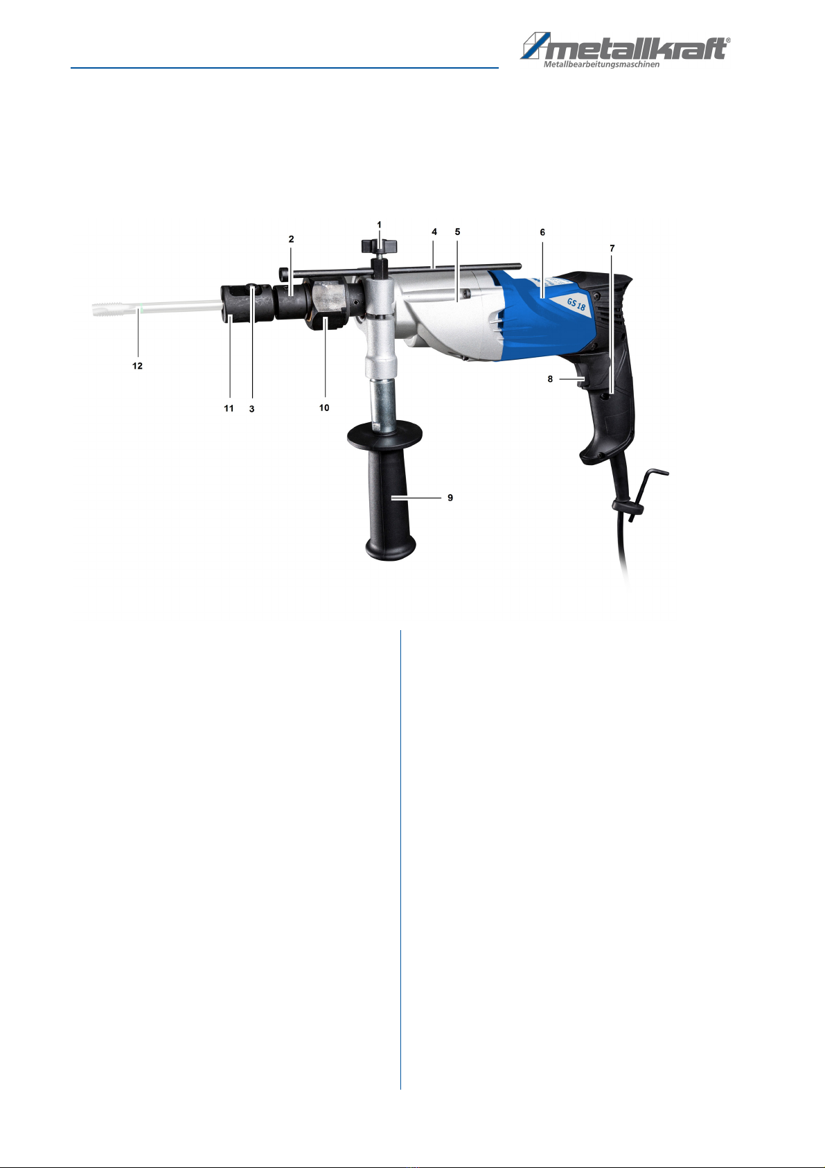
Fig. 3: Description Tapping Power Tool GS 18
1 Locking screw
2 Turning head
3 Locking screw
4 Depth stop
5 Housing
6 Motor
7 Handle
8 ON-Schwitch
9 Side handle
10 Safety friction clutch
11 Universal holder
12 Tap (not in the scope of delivery)
Scope of delivery:
- Universal holder M6 – M18 with friction clutch
- Additional handle
- 4 mm hexagon key
- Depth stop
- Transport case
Operation
GS 18 | Version 1.05 9
7 Operation
7.1 Preparation
Step 1: Place the machine on a level surface to clamp
the desired Tapping Power Tool into the clamp-
ing device.
Step 2: Open the clamp device far enough to involve the
whole shaft of the tap.
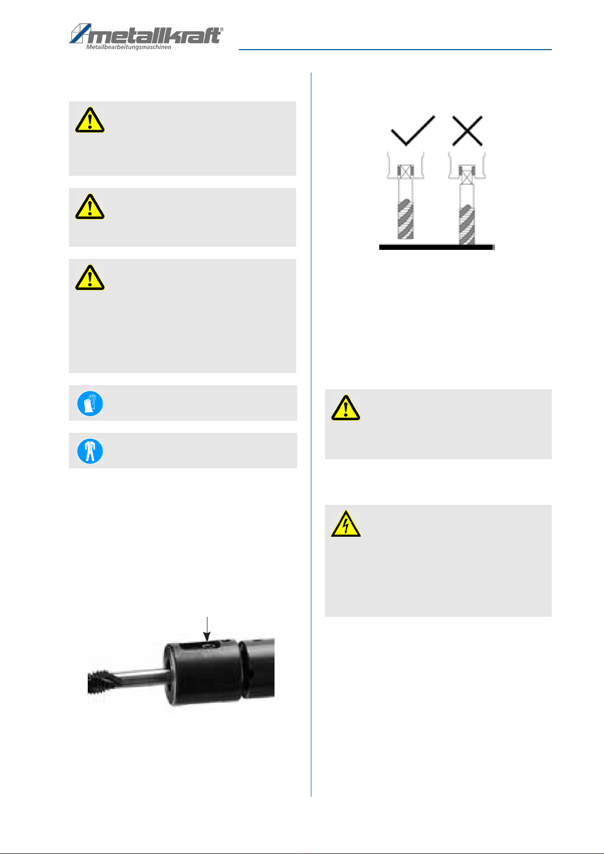
Fig. 4: Holder for taps
Step 3: Insert the tap as far as possible into the clamp-
ing device.
Fig. 5: Inserting the tap
Step 4: Close the clamping device, making sure that the
shaft surfaces do not cant when closing and that
the shaft is inserted into the clamping device as
far as possible.
Step 5: Attach the side handle to your machine to guide
the machine safely with both hands during the
cutting process.
7.2 Electrical connection
When connecting the tap, make sure that:
- the power connection has the same characteris-
tics (voltage, mains frequency, phase angle) as
the motor.
- the mains voltage of 400 V is used.
Connect the Tapping Power Tool to the mains in the fol-
lowing steps:
Step 1: Check that the motor switch is off.
Step 2: Plug in the mains plug into the 230V socket after
clamping the tool.
ATTENTION!
- Make sure that the workpiece is not under pressure
before each cutting operation.
- Check that the workpiece is securely fastened.
ATTENTION!
Before connecting the machine to the mains, check
that the motor switch is off.
ATTENTION!
Never use the machine with larger taps than the
maximum permissible diameter. In relation to steel
14 mm and aluminum 16 mm in continuous opera-
tion. In occasional operation, the tap can be oper-
ated up to a diameter of 18mm. Readjust the slip
clutch if too much slippage occurs. For this please
contact the customer service under 1.2.
Wear protective gloves!
Wear protective clothing!
Locking screw for taps
ATTENTION!
Make sure that the shaft faces of the tap are inserted
as far as possible into the chuck and that the shaft
faces do not cant when the chuck is closed.
DANGER!
Danger to life due to electric current!
There is an immediate danger of electrocution on
contact with live components.
- The tapping power tool may only be connected by
electricians.
- Work on the electrical system should only be car-
ried out by qualified electricians.

10 GS 18 | Version 1.05
Operation
7.3 Drilling
Step 1: Place the tap on the workpiece and position the
machine so that the tap is accurately centered
on the center of the core hole.
Step 2: Press the machine onto the workpiece to set the
rotation direction for screwing in.
Step 3: Start the machine by pressing and holding the
ON switch.
Fig. 6: ON- / OFF-Switch
Step 4: Make sure that the tap is exactly in line with the
core hole, during the entire cutting process.
Step 5: When the desired depth of cut has been
reached, release the On button. The machine
halts.
Step 6: Pull the machine backwards to set the direction
of rotation to bore and restart the machine by
pressing and holding the on switch until the tap
is removed from the core hole.
ATTENTION!
Never use a tool with larger dimensions than
approved by the manufacturer.
ATTENTION!
- Make sure that the workpiece is not under pressure
before each cutting operation.
- Check that the machine has been aligned exactly
to the core hole.
- Only cut with sharp tools!
- Remove chips regularly to avoid large amounts of
chips. This could damage the tool.
- The tool and the cutting residue are very hot at the
end of the cutting process. Do not touch, risk of
burns!
- When cutting, always apply cutting oil to the tool by
hand!
Wear eye protection!
Wear ear protection!
Wear protective clothing!
CAUTION!
Risk of crushing!
Improper work with the tap can result in injury to the
upper limbs.
ATTENTION!
This machine is designed exclusively for cutting
right-hand threads. Left-hand threads are not possi-
ble with this machine!
Downforce:
Clockwise
ON- / OFF-Switch

Cleaning, maintenance and service/repair
GS 18 | Version 1.05 11
Step 7: Pull out mains plug and remove chips with a tool.
7.4 Depth stop
The depth stop is useful if you have to work a blind hole
or a through hole with an obstacle behind the hole. Of
course, the depth stop can be used for each threaded
hole. You can move the depth stop forwards or back-
wards or remove it when you do not need it.
Step 1: Loosen the locking screw of the depth stop and
set it so that it is flush with the end of the tap.
This will be their zero position.
Step 2: Subtract the desired depth of cut from this posi-
tion and additional 4 mm (due to internal me-
chanics). Set this from the zero position.
Step 3: Close the locking screw.
7.5 Safety clutch
The slip clutch is designed in such a way that when the
maximum torque is reached, the clutch slips over. This
is to protect against tearing of the tap and protect the
motor.
The slip clutch is pre-set at the factory and can be read-
justed if it changes in maximum torque. For this please
contact our customer service (see 1.2).
8 Cleaning, maintenance and service/
repair
8.1 Cleaning
NOTE!
Use the supplied depth stop to keep control over the
depth of cut.
Upforce:
Counterclockwise
Tips and recommendations
To ensure that the tapping power tool is always in
good operating condition, regular care and mainte-
nance work must be carried out.
WARNING!
Danger due to insufficient qualification of
persons!!
Insufficiently qualified personnel can not assess the
risks involved in maintenance work on the machine
and expose themselves and others to the risk of seri-
ous injury.
- All maintenance work should only be carried out by
qualified persons.
DANGER!
Danger to life due to electrical shock!
There is a danger to life when in contact with live
components.
- Always unplug the appliance before cleaning and
maintenance.
- Connections and repairs of the electrical equip-
ment may only be carried out by a qualified electri-
cian.
NOTE!
After servicing, maintenance and repair work, check
that all panels and guards are properly installed on
the machine again and that there is no more tools
inside or in the working area of the tapping power
tool.
Damaged safety devices and parts must be
repaired or replaced by the customer service.
NOTE!
Oil, grease and cleaning agents are hazardous to
the environment and must not be dumped into
wastewater or normal household waste. Dispose of
these funds in an environmentally friendly way. The
cloths soaked in oil, grease or detergent are easily
flammable. Collect the cleaning rags or cleaning
wool in a suitable, closed container and dispose of
them in a manner suitable for environmentally-
friendly disposal - do not dispose of with household
waste!
12 GS 18 | Version 1.05
Cleaning, maintenance and service/repair
Clean the machine after each use.
Do not remove metal or scrap with bare hands, but use
safety gloves to prevent cuts.
Clean all painted surfaces with a soft, damp cloth.
Never use solvents to clean plastic parts or painted sur-
faces. A surface release and consequential damage
may occur.
Keep the ventilation slots of the engine free from cont-
amination to ensure sufficient cooling.
8.2 Maintenance
Every 50 hours of operation, clean the engine with com-
pressed air during operation without load. Attention!
Wear eye protection.
Always keep the spindle shaft free of dirt and swarf. Lu-
bricate the spindle shaft regularly.
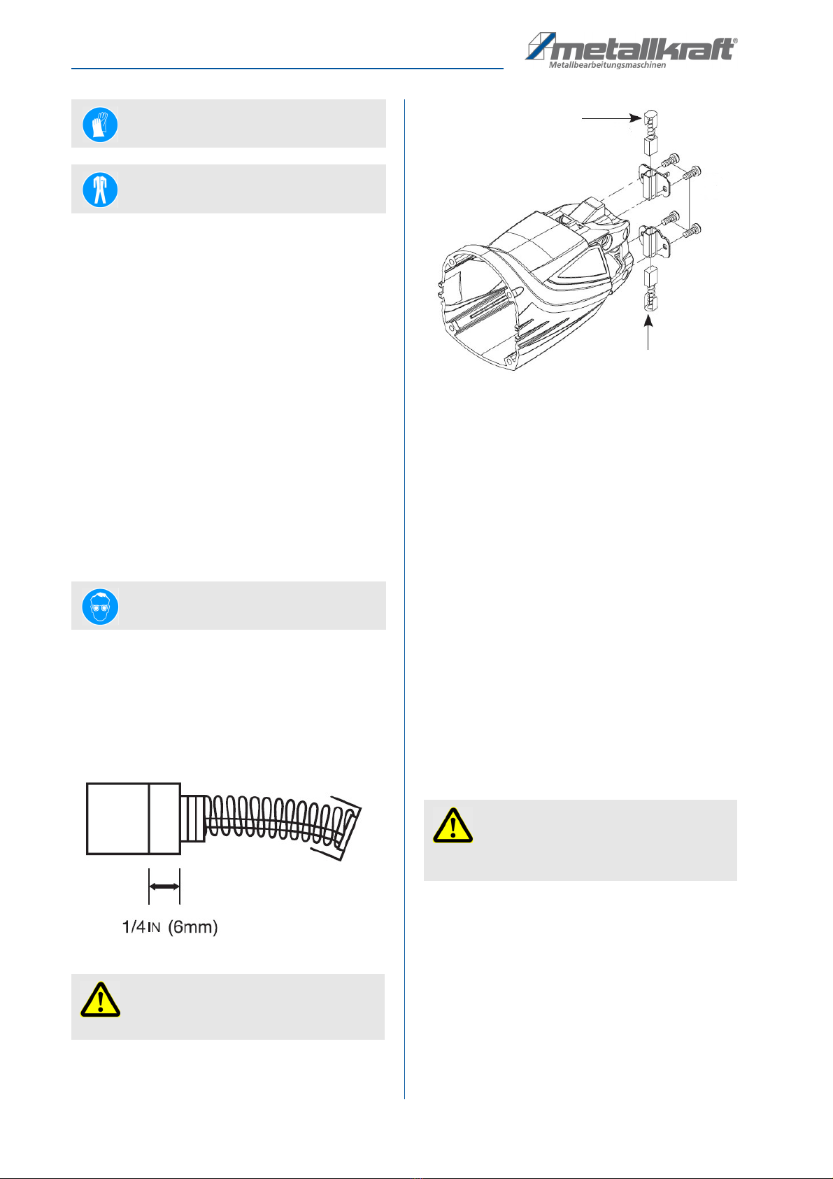
Changing the carbon brushes:
The carbon brushes are normal wear parts and must be
replaced as soon as they are worn.
Fig. 7: Carbon brushes
Fig. 8: Change carbon brush
Step 1: Unscrew the four engine cover screws and re-
move the engine cover.
Step 2: Use needle-nose pliers to push the spring aside.
Step 3: Unscrew the connection cable of the carbon
brush and remove the carbon brush.
Step 4: Insert the new carbon brush into the holder and
assemble in reverse order.
Step 5: Follow these steps on both sides.
Step 6: Screw on the engine cover.
If the machine comes to an unexpected stop, check the
carbon brushes. Due to the automatic stop, the carbon
brushes are not sanded down to the end. This serves to
protect the engine.
8.3 Servicing
As a result of wear, it may happen that maintenance
work must be carried out on the machine.
Wearing Protective gloves!
Wearing Protective clothing!
Wearing Eye protection!
ATTENTION!
Always replace the carbon brushes in pairs.
ATTENTION!
Repairs or maintenance work may only be carried
out by qualified and trained specialist personnel.
Carbon brush
Carbon brush

Disposal, Recycling of old equipment
GS 18 | Version 1.05 13
9 Disposal, Recycling of old equip-
ment
In your own interests and in the interests of the environ-
ment, please ensure that all components of the machine
are disposed of in the proper and approved way.
9.1 Decommission
Disused devices must be taken out of service immedi-
ately in order to avoid later misuse and endangering the
environment or people.
- Remove all environmentally hazardous operating fluids
from the old device.
- Disconnect the power cord.
- If necessary, dismantle the machine into manageable
and usable assemblies and components.
- Guide the machine components and operating materi-
als to the appropriate disposal routes.
9.2 Disposal of electrical equipment
Please note that electrical appliances contain a variety
of recyclable materials as well as environmentally harm-
ful components.
Make sure that these components are disposed of sep-
arately and properly. In case of doubt, please contact
your municipal waste disposal.
If necessary, the help of a specialized waste manage-
ment company can be used for the treatment.
9.3 Disposal of lubricants
Please pay attention to an environmentally friendly dis-
posal of the used coolants and lubricants. Observe the
disposal instructions of your municipal disposal compa-
nies. The disposal instructions for the lubricants used
are provided by the lubricant manufacturer. If neces-
sary, ask for the productspecific data sheets.
10 Spare parts
10.1 Ordering spare parts
The spare parts can be obtained from the dealer or di-
rectly from the manufacturer. The contact details are in
chapter 1.2 Customer Service.
When ordering spare parts, please use the spare parts
document accompanying the machine.
- Type of device
- Serial number
- Quantity
- Designation
- Required mode of dispatch (mail, freight, sea, air,
express)
- Address of dispatch
Spare part orders which do not include the above indi-
cations may not be taken into consideration. If the indi-
cations regarding the mode of dispatch are missing, the
product is dispatched at the discretion of the supplier.
Information on the device type, article number and year
of manufacture can be found on the type plate, which is
attached to the device.
ATTENTION!
For maintenance work, please contact your nearest
metalworking dealer. Please write down the follo-
wing information from the machine or the operating
instructions beforehand so that you can be helped in
the best possible way with your problem:
- Model of the machine,
- Serial number of the machine,
- Hydraulic data
- Exact error description
DANGER!
Risk of injury due to incorrect spare
parts!
The use of incorrect or faulty replacement parts can
be dangerous to the operator and cause damage
and malfunction.
- Only original spare parts from the manufacturer or
replacement parts approved by the manufacturer
must be used.
- In case of doubt, always contact the manufacturer.
Tips and recommendations
Using non-approved spare parts voids the manu-
facturer's warranty.

14 GS 18 | Version 1.05
Spare parts
Example
The motor housing of the thread cutter GS 18 must be
ordered. The motor housing has the position number 14
in the spare part drawing.
- Type of device: Tapping Power Tool GS 18
- Item number: 3860018
- Position number: 14
The order number is: 0-3860018-14
The order No. consists of the item No (3860018), the po-
sition No. (14) and one digit in front of the item No. (0).
- Place the digit 0 in front of the item No.
- Also place the digit 0 in front of the position No 1
through 9.
The order number is: 3860018.

Spare part drawing
GS 18 | Version 1.05 15
11 Spare part drawing
In case of service, the following drawing shall help to identify the necessary spare parts. If necessary, send a copy of
the parts drawing with the marked components to your authorized dealer.
Fig. 9: Spare part drawing GS 18
16 GS 18 | Version 1.05
Electrical wiring diagram
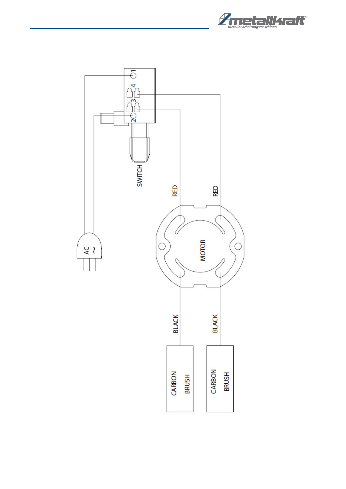
12 Electrical wiring diagram
Fig. 10: Electrical wiring diagram GS 18

EC Declaration of conformity
GS 18 | Version 1.05 17
According to machine directive 2006/42/EC Annex II 1.A
Manufacturer/retailer: Stürmer Maschinen GmbH
Dr.-Robert-Pfleger-Starße 26
D-96103 Hallstadt
herewith declares that the following product
Product group: Metallkraft®Metallbearbeitungsmaschinen
Machine type: Tapping Power Tool
Designation of machine: GS 18
Item number: 3860018
Serial number: ____________________
Year of manufacture: 20____
corresponds, on the basis of its design and construction, as well as the version that we have put into circulation, with the
relevant fundamental health and safety requirements of (subsequent) EC guidelines.
Relevant EU directives 2014/30/EU EMC-Directive
2011/65/EU RoHS-Directive
The following harmonized standards were applied:
DIN ES ISO 12100:2010 Safety of machinery - General principles for design -
Risk assessment and risk reduction
DIN EN 60204-1:2007-06 Safety of machinery - Electrical equipment of machines -
Part 1: General requirements
DIN EN 61029-1:2009+A11:2010 Safety of transportable motor-operated electric tools
Part 1: General requirements
Responsible for documentation: Kilian Stürmer, Dr.-Robert-Pfleger-Str. 26, D-96103 Hallstadt
Hallstadt, 20/07/2016
______________________
Kilian Stürmer
Manager
13 EC Declaration of conformity

www.metallkraft.de
This manual suits for next models
1
Table of contents
Other Metallkraft Power Tools manuals


