Huawei CG1-2 User manual


CG1-2A H Beam cutter
1
INSTRUCTION
Thank you very much for purchasing this product. Read this instruction
manual thoroughly to insure correct, safe and effective use of the machine.
Read the manual first to understand how to operate and maintain the
machine.
Make sure you read, understand and take all the necessary safety
precautions.
SAFETY PRECAUTIONS
This product is designed to be safe, but it can cause serious accidents if not
operated correctly. Those who operate and repair this machine must read
this manual thoroughly before operating, inspecting and maintaining the
machine. Keep the manual near the machine so that anyone who operates
the machine can refer to it if necessary.
■ Do not use the machine carelessly without following the instructions in
manual.
■ Use the machine only after you completely understood the contents of
the manual.
■ If an explanation in the manual is difficult to understand, contact our
company of sales service office.
■ Keep the manual nearby at all times and read it so many times as
necessary for a complete understanding.
■ If the manual become lost or damaged, place an order with our company
or sales service office for a new one.
■ When transferring the machine to a new owner, be sure to hand over this
instruction manual as well..
QUALIFICATIONS FOR MACHINE OPERATOR
Operators and repair staff of this machine must completely understand the
contents of the instruction manual and they must be qualified and educated
to handle this equipment.
1. The license for gas welding ganger
2. The diploma of the training course on gas welding.
3. The qualification certificate approbated by the ministry of labor.

CG1-2A H Beam cutter
2
Symbol
Title
Meaning
General
General caution, warning and danger
Be careful not to get your
fingers caught.
Possible injury to fingers if caught in the
insertion part.
Caution: Electric shock!
Possible electric shock under special
conditions.
Ground this equipment.
Operators must ground the equipment
using the safety grounding terminal.
Pull out the power plug
from the outlet.
Operators must unplug the power plug from
the outlet when a failure occurs or when
there is a danger of lightning.
Caution against bursting
Possible bursting under certain conditions.
General
General warning.
Caution: Hot!
Possible injury due to high temperature
under certain conditions.
Caution: Ignition!
Possible ignition under certain conditions.

CG1-2A H Beam cutter
3
CONTENTS
1. Safety Information ............................................................................................1
1.1General machine safety precautions ..................................................................1
1.2 Gas cutting safety precautions...........................................................................3
2. Outline of machine ...........................................................................................5
2.1Features of machine............................................................................................5
2.2 Name and function of each section....................................................................6
2.3 Specifications .....................................................................................................6
3. Preparation for operation..................................................................................7
3.1 Contents of package ..........................................................................................7
3.2 Introduction of section function ..........................................................................7
3.3 Machine assembly..............................................................................................9
3.4 Preparation before operation .............................................................................10
4. Cutting operation..............................................................................................11
4.1 Safety measure prior to operation......................................................................11
4.2 Ignition and flame adjustment ............................................................................11
4.3 Cutting and piercing method ..............................................................................12
4.4 Beginning of cutting operation............................................................................12
4.5 Notice of slanting cutting web plate ...................................................................15
4.6 Bevel cutting operation ......................................................................................15
4.7 Safety measures against backfire and flashback..............................................16
5. Maintenance and inspection.............................................................................16
5.1 The maintenance of the gears box ....................................................................16
5.2 Maintenance of the tip........................................................................................17
5.3 Maintenance of the carbon brush.......................................................................17
7. Trouble shooting ..............................................................................................17
8. Wiring diagram.................................................................................................19
9. Maintenance illustration....................................................................................20

CG1-2A H Beam cutter
- 1 -
Safety instruction
Operation, inspection, and maintenance that disregard the basic safety rules cause many
accidents. Carefully read, understand, and master the safety measures and precautions
described in this instruction manual and on the machine before operating, inspecting, and
maintaining the machine. The safety messages are classified as indicated on the machine
safety labels:
■ WARNING
This word is used in a warning message and a warning label is positioned at places that
could cause injury or serious accident.
■ CAUTION
This word is used in a caution message and a caution label is positioned at places that
could cause slight injury or machine damage. This is also used as a caution for frequent
dangerous actions.
■ NOTICE SIGNS
This is a sign to show machine operators and maintenance engineers items that relate
directly to damage of machines and surrounding facilities and equipment.
1.1 General machine safety precautions
Read and understand the following important safety information:
1.1.1 Machine safety
1. The machine casing is mainly made of aluminum alloy to reduce weight. For this reason,
be careful not to drop a heavy item on the machine, or not drop the machine when carrying
it , since the alloy is not designed to withstand such impact.
2. When mounting hoses to the torch and distributor, tighten the nut with the attached
wrench. After mounting, be sure to check there is no gas leak with a detection liquid. If a gas
leak is found, retighten the nut firmly.
3. When fixing a tip to the torch, tighten the nut with the two wrenches attached. In addition,
avoid damaging the taper part of the tip since this may cause backfire.
4. Never disassemble the machine other than during maintenance and inspection. Otherwise,
malfunction will result.
5. Never remodel the machine. Remodeling is very dangerous.
6. Always turn the power off when not in use.
7. Never use the machine outdoors when the weather is wet. This will cause failure of the
machine and could cause a fatal accident by electric shock.
1

CG1-2A H Beam cutter
- 2 -
1.1.2 Safety clothing
1. Be sure to wear protector’ s gauntlets, goggles, helmet, and safety shoes during
operation.
2. Avoid operating the machine with wet clothes or hands in order to prevent electric shock.
1.1.3 Operation and handling safety precautions
1. Read this instruction manual before operating the machine.
2. Make sure the machine runs normally and perches rightly before operation.
3.Before opening power, make sure the drive knob is in the stop position which is in the
middle.
4. Prior to operating the machine, check the safety of the surroundings to avoid accidents.
5. Never move the machine while the preheat flame is on.
6. When use track to cut, clear groove of track. Otherwise, it will affect track of machine and
cutting quality.
7. Notice: Don’ t bump or knock track.
8. Lifting device of machine has device to avoid knocking. If torch is knocked, small gear
disengages from vertical gear rack and does not damage mechanic parts.
1) Close quadruple switch to stop vertical drive.
2) Hold lifting bar to arise torch. When low lifting bar, gear and gear rack engages
automatically. Low lifting bar slowly, otherwise, impact of falling damages rolling pin.
12. Direction changeover switch
The direction changeover switch is used to change the direction of cutting between
clockwise and anticlockwise. Check the running direction or the direction of revolution button
before cutting.
When changing the direction of running, make the driving button in the stop position.
And change the direction of running after the machine comes to a full stop.
Instruction: Before electrifying, it is necessary to check if the driving button is in the stop
position. It is very dangerous to turn on the machine when the driving button is in the open
position.
13. Do not touch the revolution parts during the operation process, because it is very
dangerous!
14. Keep the machine from vibrating during the cutting process.
15. The gas used for the cutting process is dangerous in the case of wrong operation, so it is
necessary to connect the fuel gas hose correctly..
16. You must close preheat valve and fuel gas valve when checking the running of the
machine before operation and cutting allocation.
17. The bottom of the tip, torch and the butterfly-screws etc are very hot after cutting, so it is
necessary to wear gloves if you want to touch them.

CG1-2A H Beam cutter
- 3 -
18. You must not drag the cable conductor of power supply.
19. Don’ t leave the machine alone before it flames out.
20. The gas-in junction must be locked tightly used the hose-hoop in order to prevent serious
accident caused by gas leakage.
21. When the fuse burns out frequently, it is not allowed to use the fuse bearing high-current
before finding out the cause.
22. When moving the machine it is not allowed to drop, bump or shake it strongly.
1.1.4 Electrical system precautions
1. Be sure to check the input power voltage of the machine before operation. The input
power voltage should be in the range of ±10% of the rated voltage. The machine should not
be operated out of this range.
2. The metal plugs are screw-threaded, therefore, fully tighten them so that they will not
come loose during operation.
3. Be sure to ground the power cable of the machine.
4. Stop operation and turn off the power in the following cases, and ask a qualified electrician
to repair the machine.
1) Broken or abraded cables
2) When the machine has been in contact with water, or in case of liquid damage to the
machine.
3) Abnormal machine operation despite operating the machine according to the instruction
manual
4) Machine breakdown
5) Poor machine performance the requires repair
5. Periodically inspect the electrical system.
1.1.5 Maintenance and inspection precautions
1. Ask a qualified electrician to perform repair and inspection service.
2. Disconnect the power plug before inspecting and repair the machine.
3. Maintain the machine periodically.
1.2 Notice instruction before the operation of air cut.
Strictly observe the safety rules and precautions to ensure the safety of gas cutting
operations.
Operators and supervisors MUST keep safety in mind.
1.2.1 Prevention of explosion
1. Never cut pressurized cylinders or hermetically sealed containers.
2. Ensure sufficient ventilation for gas cutting to prevent the air from becoming stale.

CG1-2A H Beam cutter
- 4 -
1.2.2 Pressure regulator safety precautions
1. Before starting operation, check that all pressure regulators are operating correctly.
2. Ask a skilled repair engineer to perform maintenance and inspection service.
3. Do not use pressure regulators from which gas is leaking, or malfunctioning pressure
regulators.
4. Do not use pressure regulators smeared with oil or grease.
1.2.3 High pressure gas cylinder safety precautions
1. Never use broken cylinders or cylinders from which gas is leaking.
2. Install cylinder upright and take measures to prevent them from falling.
3. Use cylinders only for specified purposes.
4. Do not smear container valves with oil or grease.
5. Install cylinders in a place free from heat, sparks, slag, and open flame.
6. Contact the distributor if the container valves will not open.
Never use a hammer, wrench, or other tools to forcibly open container valves.
1.2.4 Safety precaution for hoses
1. Use the oxygen hose for oxygen gas only.
2. Replace cracked hoses or other hoses damaged by sparks, heat, unshielded fire, etc.
3. Install hoses without twisting.
4. To prevent breakage of hoses, take great care during operation and transportation.
5. Do not hold the hoses when moving the machine.
6. Periodically check the hoses for damage, leakage, fatigue, loose joints, etc, to ensure
safety.
7. Cut hoses to the minimum possible length. Short hoses reduce hose damage and
pressure drop, as well as reduce the flow resistances.
1.2.5 Safety precautions for fire
Take safety precautions to prevent fire prior to gas cutting.
Ignoring hot metal, sparks, and slag could cause a fire.
1. Keep a fire extinguisher, fire extinguish sand, bucket full of water, etc. ready on the site
where gas cutting is performed.
2. Keep flammables away from the cutting area to avoid exposure to sparks.
3. Always cool down steel plates that have become hot after cutting, as well as hot cut parts
or scrap, before bringing them close to flammables.
4. Never cut containers to which flammable materials are stuck.

CG1-2A H Beam cutter
- 5 -
1.2.6 Safety precautions for skin burns
Observe the safety precautions to prevent skin burns. Ignoring heat, spatter, and sparks
during operation could cause a fire or burned skin.
1. Do not perform cutting near flammables. (Move flammables well away from the sparks.)
2. Do not cut containers filled with flammables.
3. Do not keep lighters, matches, and other flammables nearby.
4. Flames from the torch will burn the skin. Keep your body away from the torch and tip, and
check the safety before operating the switches and valves.
5. Wear the correct protectors to protect your eyes and body.
6. Correctly tighten the tip to prevent backfire.
● When fixing a tip to the torch, tighten the nut with the two wrenches attached.
● If the tip is tighten excessively, it will be heated during cutting and tightened still more,
making it difficult to remove the tip.
● Avoid damaging the taper of the tip since this may cause backfire.
7. Check with soapsuds for any leakage of gas from the connection part of the distributor,
hoses and torch. Never use oil or grease on the connection of the oxygen pipe to avoid
backfire which may lead to explosion.
8. Be sure to check the following when igniting:
●Place the torch on the torch holder before igniting.
●Wear the required protectors (gauntlets, helmet, goggles, etc.)
● Check for any obstacles, dangerous materials and flammables near or in the direction of
cutting.
● The surface temperature is very high, so do not touch it even you wear gauntlets.
Outline of machine
2.1 Features of machine
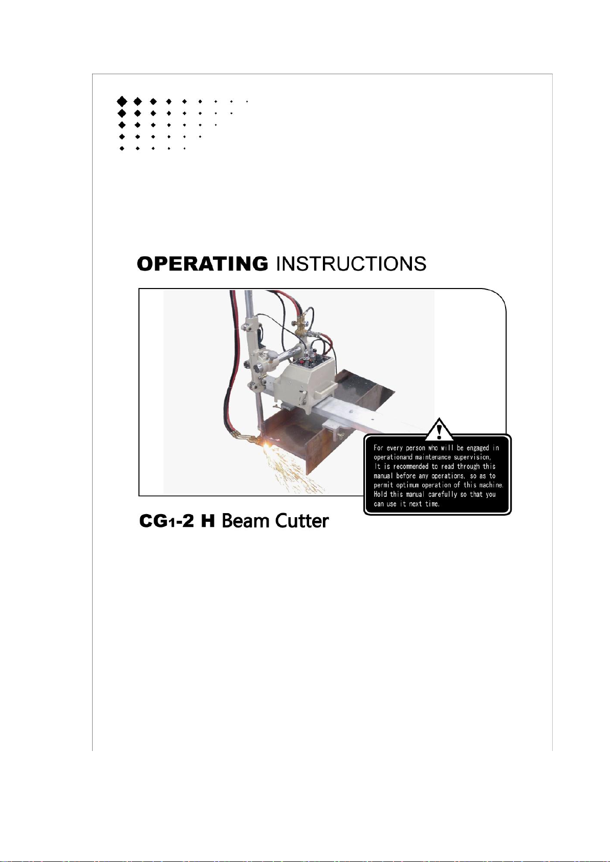
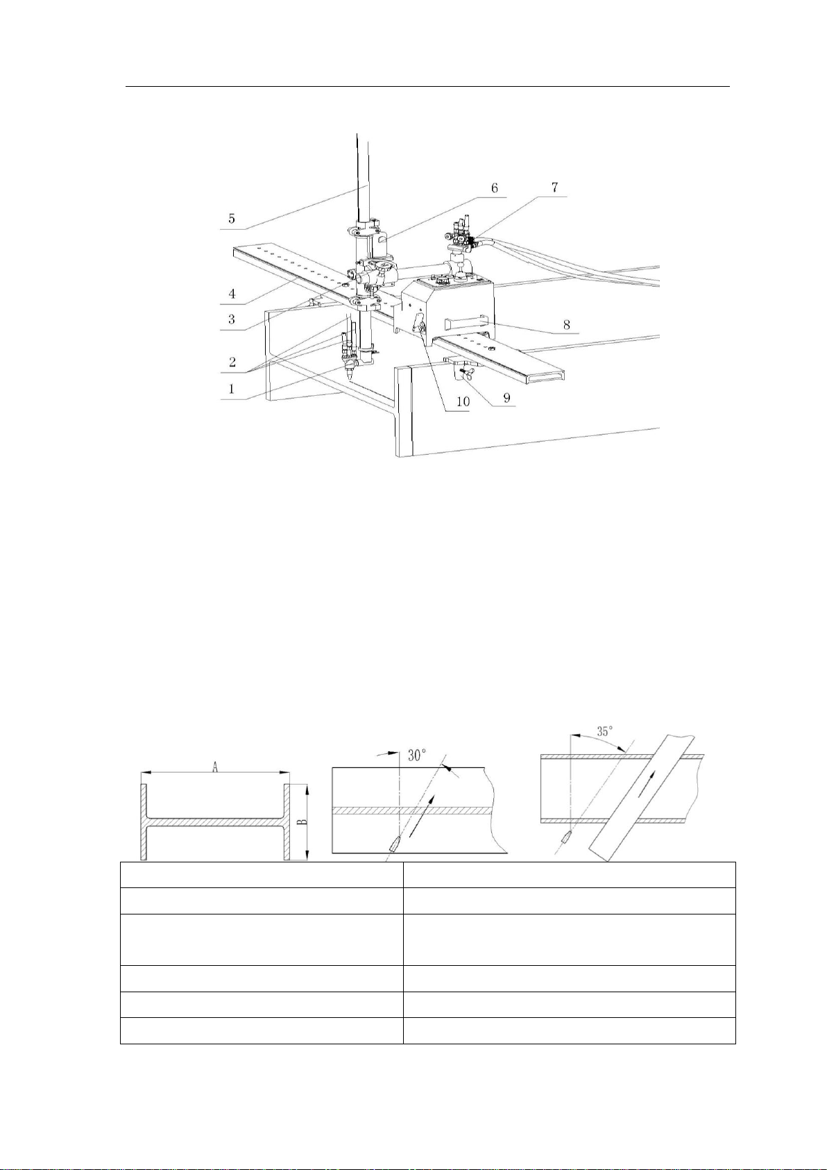
“CG1-2A” portable H Structural section gas cutter is designed for cutting large-sized
structural section. The cutter is constituted of web plate cutting mechanism, wing plate
cutting mechanism, control box, gas distributor and torch. The shell of cutter is made of
aluminum. Every section is connected with web plate cutting mechanism. The web plate
mechanism is composed of box of reducing speed, motor and clutch. The web plate cutting
mechanism walks on the track with four rollers. The wing plate cutting mechanism is installed
on one side of the web plate and four pulley sustaining bars move vertically in the way that
gear moves with gear rack. Design of the cutter is reasonable and the cutter is easy to check
and repair. All operations are completed on the control panel such as quadruple switches,
quick return push-button, speed modulation, power source switch. It is easy to master the
operations even if freshman.
2

CG1-2A H Beam cutter
- 6 -
2.2 Name and function of each section
1. Torch
7. Quick distributor: Flame is adjusted
only once and not adjusted again.
8.Handle: It is to move machine
2.Gas hose: connected between torch and
gas distributor to deliver gas,
3. Adjusting pilot wheel for transverse: It is
to control torch transverse movement.
9. Track pressure plate: Locate
machine on the H structural section
4.Track
10. Clutch knob: Pulling knob on the left
side is off, pulling knob on the right side
is on.
5.Vertical moving bar
6.Reduce speed motor of web plate cutting
equipment
2.3 Specifications
1.Weight (body)
:21.5kilograms
Accessory(track sections)
:15.5 kilograms
2.Machine dimension
:400mm×340mm×440mm(Body);
: 270mm×220mm×2200mm(Track)
3.Speed control
:SCR control
4.Power source
:AC 220V±10%
5.Cutting speed
:50~750 ㎜/min

CG1-2A H Beam cutter
- 7 -
6.Cutting thickness
:5-50mm
7.Bevel angle
:0~30°(wing plate; web plate)
8.Maximum fly past of web plate cutting
:A=1600mm
9.Maximum fly past of wing plate cutting
: B=800mm
10.Maximum angle of wing plate slanting
cutting
:30°(maximum height of slanting cutting 690mm)
11.Maximum angle of web plate slanting
cutting
:35°(maximum length of slanting cutting 1300mm
9.Tip
:G02(for acetylene) or G03(for propane)
10.Motor
: 1) web plate motor 110V 50HZ 30W
Rotational speed,3600 rpm
: 2) wing plate motor 110V 50HZ 40W
Rotational speed,2200 rpm
Preparation for operation
3.1 Contents of package
Carefully take the machine out of its case. Check them carefully before assembling the
machine. The contents of the standard package are shown in the following list.
1)Body
1
2)Standard torch and sections
1
3)Wing plate mechanism
1
4)Tip(G02 or G03 #1,2、3,)
1
5) Track(include track pressure plate)
1
6) Inlet gas joint
1
7)Spanner
1
8) Specification sheets and certificate of qualification
1
9) Power cable
1
10) M5 inner hexagon spanner
1
11) Phillips screwdriver
1
12) Needle
1
3.2 Introduction of section function
1) Quick distributor
Gas distributor uses integrated flame adjuster. Preheating flame and cutting oxygen are
adjusted once. After that, property of flame keeps same with adjusting rotating angle of
knob to turn on or off gas source when each cutting is finished.
Turn off position: cut off gas and oxygen
Preheating position: connect preheating flame and keep same
3

CG1-2A H Beam cutter
- 8 -
Cutting position: preheating flame and cutting oxygen turn on and cutting begins.
State of close State of preheat State of cutting
2) Application introduction
Pull quick distributor switch knob in the preheating position, ignition and adjust flame.
Adjust valve to get best preheating flame. According to recent pressure, pull the knob in the
cutting position and adjust oxygen flow when preheating flame is on. After these operations,
pull the knob in the off position, repeat adjusting from preheating flame to cutting oxygen
until be sure that flame is on normally. If pressure verifies, adjusting is needed again.
3) Quadruple switch
Sub switch is to control running direction of web plate motor and wing plate motor;
interlocks with cutting oxygen. There are four arrows on the control panel. When operating
bar of quadruple switch is pulled on the arrow side, it is running machine. Operating bar of
switch returns to original position, machine stops running and cutting oxygen turns off.
4)Fast-moving switch
Switch is in the center of control panel. When
press the switch, web plate motor and wing
plate motor run at maximum speed
(about750MM/MIN). Sub function is convenient
for torch going forward and back quickly. When
handle of quick distributor is in the cutting
position, cutting oxygen stops supplying in the
work.
5) Pilot wheel for transverse: Tip is convenient to align mark line.

CG1-2A H Beam cutter
- 9 -
6) Wing plate angle control equipment
Set angle when slanting cut wing plate.
7) Speed modulation
Velocity label is divided ten grills. The relationship between grill and velocity is shown in the
diagram.
8) Clutch knob
It is mainly used in web plate cutting automatic running, as well as adjusting distance
between tip and wing plate and fixing the machine on the track.
9) Lifting spacing switch of wing plate cutting
Adjust cutting position with height of wing plate. When cutting wing plate is completed, the
machine stops running and cutting oxygen is cut off. At the same time, descending spacing
switch is to insure machine is out of danger. When lifting bar elevates the limit position, the
machine stops running.
10) Track equipment
Track system includes a fixed pressure plate, a movable pressure plate and a web plate
angle adjuster. Butterfly screws of two pressure plates clamp wing plates which are in the
both sides of H structural section. When size of web plate verifies, position of movable
pressure plate can verify.
When cut web plate, release fixed angle screw and use hold down plate in line cutting. When
slanting cut web plate, choose angle and label of track aligns scale of fixed pressure plate.
3.3 Assembly equipment
1. The machine is put into two boxes. Carefully take the machine out of its case.
2. Take out cutting equipment and insert traversing bar of body. Adjust pilot wheel in suitable
position and locked tightly with slug screw. Connecting line of motor (eight-core plug) is
connected on the control panel.
3. Take out torch and fix torch connector on the lifting bar whose mark aligns “ 0” grill. And
lifting bar is locked tightly with butterfly screw. Connect cutting oxygen hose of torch with
inlet gas joint of electromagnetic valve. After that, check gas leakage with soapy water.

CG1-2A H Beam cutter
- 10 -
3.4 Preparation before operation
3.4.1 Connection of power cable
1. Before plugging the metal plug on the cabtyre code side into the socket on the machine
side, check there is no sundries or dust.
2. The metal plugs are screw-threaded, therefore, fully tighten them so that they will not
come loose during operation.
3.4.2 Connecting the tip
1. Select a proper tip according to the thickness of the steel plate and attach it to the torch.
(To select a tip, refer to the cable of Cutting Data.)
●When fixing a tip to the torch, tighten the nut with the two wrenches attached.
●If the tip is tightened excessively, it will be heated during cutting and tightened still more,
making it difficult to remove the tip.
●In addition, avoid damaging the taper of the tip since this may cause backfire.
3.4.3 Machine fixation
1. First, put fixed pressure plate and track on the H
structural section and fixed pressure plate clamps wing
plate of one side of H structural section.
2. According to web plate size, choose suitable position
of wing plate which is on the other side of H structural
section and fix movable pressure plate. Screw up
butterfly screws of two sides of pressure plate to fix track on the wing plates which is on the
two sides of H structural section.
3. Fix the machine on the track.
4. Connect primary hose with gas distributor and adjust pressure value to specified value in
order to insure connection of hose without mistake.
5. Open source of power switch which is on the control panel and indicating lamp lights.
Check operating bar of quadruple switch whether it is in the off position.

CG1-2A H Beam cutter
- 11 -
Cutting operation
4.1 Safety measures prior to operation
4.1.1 Safety precautions for grounding the machine
The cable of this machine is equipped with a
grounding wire. For safety, be sure to ground
the wire as follows, in addition to checking the
connection of the power cable. (As shown in
diagram)
4.1.2 Selection of tip
Referring to the Cutting Data, Select the
suitable tip according to the plate thickness.
For a heavily rusted plate or for a bevel cutting
angle of more then 20°, select the tip one grade higher than the one shown in the cutting
Data.
4.1.3 Operation of quadruple switch
1. When machine needs to change direction, pull operating bar of quadruple switch in the off
position. When machine stops running, change the position to run.
2.Move machine when operating bar of quadruple switch is in the off position.
3.Before open power, pull operating bar of quadruple switch in the off position. If it is in
other position, machine runs when open power, which is dangerous
Notice: before open power, it is necessary to check whether drive knobs are in the off position.
If drive switch is in the on position, it is dangerous to run machine.
4.2 Ignition and flame adjustment
NOTE: Adjust the gas pressure according to the Cutting Data. The data shows the pressure
when all valves are open. Readjust the pressure after ignition.
1. Open the fuel gas valves 1/4 to 1/2 a turn, and light the torch with an igniter.
2. Then, open the preheating oxygen valve gradually until a white cone of the standard
flame gas been obtained. (The incandescent area should be uniform and about 5-6 mm
in length.)
3. Open the jet oxygen value fully. Readjust the flame if its condition has changed. A
disorderly flow of the jet oxygen will adversely affect the quality of the cutting surface. In
such a case, clean the tip with a suitable cleaning needle while the jet oxygen is flowing.
4. Appropriate distance between the tip end and cutting surface:
● Acetylence gas ………..8-10mm
● LPG gas ……………..5-8mm
4

CG1-2A H Beam cutter
- 12 -
5. Neutral flame ensures good quality cut surfaces. (Oxygen flame may be used for bevel
cutting.)Oxygen flame causes short cutting-oxygen current, allowing slugs to adhere, melting
the upper edge of the cutting surface, and causing adverse effects on the cut surface. Similar
defects will result when the cutting oxygen pressure is too high.
4.3 Cutting and piercing method
1. Cut in from the end of steel plate.
2. Pierce steel plate before cutting.
3. Drill a hole before cutting.
■ Piercing method
1) Ignite and adjust the flame.
2) Thoroughly preheat the cut-in point until it is white hot.
3) Open the cutting oxygen valve to pierce the steel plate. The tip should be about 15-20
mm from the plate to prevent slag from splashing onto the tip and adhering there,
which will shorten the working life of the tip.
4.4 Beginning of cutting operation
1. Release clutch of machine and pull the torch on the edge of wing plate edge which is on
one side of H structural section. Put torch horizontally. Then put quick knob in the preheating
position. Ignite torch and adjust flame. (Refer to quick distributor adjustment in detail)
2. When use preheating flame, set quadruple switches in the descending position and push
quick knob to low tip and be close to surface of wing plate. Adjust the distance between tip
and wing plate. The distance range is about 7 to 10mm. Then close the clutch.
3.Move tip center under the lower limb of wing plate 5mm and torch stops descending. At
that moment, set torch descending spacing switch.
4.Set cutting speed.
5.Put quadruple switch in the ascending position. Tip center moves upwards and aligns
cutting starting point which is near the wing plate. And preheat cutting starting point. (as
shown in the diagram 1)

CG1-2A H Beam cutter
- 13 -
6.Preheat cutting starting point fully. Put quick knob in the
cutting position and put quadruple switch in the
ascending position. Torch moves upwards. Cutting
oxygen ejects automatically through interlocking between
electromagnetic valve and quadruple switch and cutting
works automatically. (As shown in the diagram2.)
Check cutting state carefully and use speed control device
to control cutting speed. When torch cuts in the middle
part of web plate, the torch should reduce speed slowly (1
to 1.5 graduations in degrees). When torch goes through
surface of web plate, it returns to initial speed. The aim is
to cut web plate in the suitable depth and it is convenient to cut next web plate. The ideal
cutting depth is about 20mm. (as shown in the diagram 3)
7.When tip leaves web plate edge, press quick knob quickly until torch center rises about
300mm over wing plate upper limb. Then put quadruple switch in the off position.
8.Use pointed chipping hammer to clean slag on the web plate.
9.Release clutch and pull machine to go forwards along with the track. Rotate torch 90
degree and keep torch vertical.10 Pull down quadruple switch and tip descends 7 to 10mm
over web plate surface. It is convenient to use quick knob. Tip can not touch web plate.
11. Tip aligns web plate edge, then, close clutch. After preheating cutting starting point fully,
put quadruple switch in the left position and machine starts cutting automatically. Cutting
speed is faster than cutting wing plate. Because web plate is thinner than wing plate. (As
shown in the diagram 4)

CG1-2A H Beam cutter
- 14 -
12. When torch moves over the surface of wing plate 3mm to 4mm, pull up quadruple
switch. Hold lifting bar to rise and rotate torch in order to keep horizontally. When torch
center rises over wing plate upper limb 30mm, torch stops running.(as shown in the
diagram 5)
13.Release clutch and push the machine to go forwards and remove outboard of H
structural section wing plate. Use quick knob to low torch and make tip center reach
edge of wing plate.
14.Adjust distance between tip and wing plate and the distance is about 7 to 10mm. Close
clutch and lock cutting starting point and preheat wing plate.
15.After preheating cutting starting point fully, pull down quadruple switch and machine
descends and cuts automatically. (as shown in the diagram 7)
16.When torch cuts middle part of web plate, the torch should reduce speed slowly (1 to
1.5 graduations in degrees). When torch goes through surface of web plate, it returns
to initial speed.
17.When cutting is completed, descending spacing switch stops wing plate running
automatically. At the same time, cutting oxygen is cut off. Put quadruple switch in the
off position.
Notice: avoid that cutting work piece falls and strikes tip in the process when cutting is
completed. When work piece falls, release clutch and push machine to go forwards
along the track or use other methods to protect tip.
18. After cutting, arise lifting bar and lifting bar stops until torch stops in the position of
ascending spacing switch. Avoid knocking torch and damaging lifting sections, torch
and some sections when take apart track and machine. (as shown in the diagram 8)

CG1-2A H Beam cutter
- 15 -
4.5 Notice of slanting cutting web plate
1.There is an angle scale plate on the fixed track pressure plate. Track mark allocates on
the specified angle which is locked with nuts. Use nuts to lock. Then fix track and machine
on the H structural section.
2.Slanting cutting is different from line cutting. Torch angle needs to be adjusted, otherwise,
cutting is not whole. And some areas are not cut. As shown in the diagram 1.Adjusting
method is shown in the diagram 2 and 3. When cut wing plates, only recover bevel
graduations to zero.
4.6 Bevel cutting operation
When cutting bevel, use the angle (use 5°as its basic unit)on the
torch holder and allocate the torch on an expected angle. When
choosing a tip for bevel cutting, the thickness of the steel plane
is L as shown in following picture. In order to compensate the
over-dose heat loss due to the bevel cutting, the operator should
choose an upper rank tip based on the Cutting Data. Slight

CG1-2A H Beam cutter
- 16 -
oxygenized flame will lead to an increase of efficiency and set the speed with a decrease of
20%~30%.The bevel cutting surface in the diagram is a result of inadequate preheating,
which requires to change the tip and readjustment of the preheating and speed.
4.7 Safety measures against backfire and flashback
4.7.1 Prevention of backfire
Backfires may cause serious accidents or fire. Be careful to prevent such disaster. When a
Backfire occurs, find the cause and inspect and maintain the machine correctly before using
the machine again.
The followings are causes of backfire:
1. Improper gas pressure adjustment
2. Overheated tip
3. Slag clogged in tip
4. Damage to the tapered section of tip or torch will cause backfire.
4.7.2 Prevention of flashback
Flashback could cause fire and break the machine. Should there be a hissing sound in the
torch, quickly take the following action:
1. Close the preheating oxygen valve.
2. Close the fuel gas valve.
3. Close the cutting oxygen valve.
Should flashback occur, find the cause and take appropriate action before using the machine
again.
Maintenance and inspection
Refer to the following points for maintaining and inspecting the machine in order to use the
machine under the best conditions.
6.1 Maintenance of the gear case
1. Because there are gears that run at a high speed in the gear case, so the operator should
remove the shell of the machine, take out the gear case and wash the gears and the case
with detergent every seven months. When reassembling, we should put new lubricant into
the machine. If the turbine is abraded, we must change a new one.
2. The big rotary gear is an important part, so the gear slot should be kept clear and
lubricated and the operator must add lubricant every time. If there are sundries in the gear
slot, the operator must take them out immediately and wash the gear slot, and add new
lubricant.
6
Table of contents
Popular Cutter manuals by other brands

AKYAPAK
AKYAPAK AHS Operation and maintenance manual

HSS Hire
HSS Hire 597 Operating & safety guide

ShopBot
ShopBot Buddy Installation

Full Spectrum Laser
Full Spectrum Laser MUSE TITAN V3 user manual

ESAB
ESAB Cutmaster 120 operating manual

Weber Rescue Systems
Weber Rescue Systems S 270-71 operating instructions

Belshaw Brothers
Belshaw Brothers Donut Cutter Type F Operator's manual

Koike Sanso Kogyo
Koike Sanso Kogyo EDGE-CUT Operation manual

Skil
Skil 9816 instructions

Husqvarna
Husqvarna K6500 II Chain Operator's manual

Pace Technologies
Pace Technologies MEGA-T250S instruction manual

Bush Hog
Bush Hog TOUGH Squealer SQ142 Operator's manual