Shannon HRK 65 User manual
User’s Guide
English
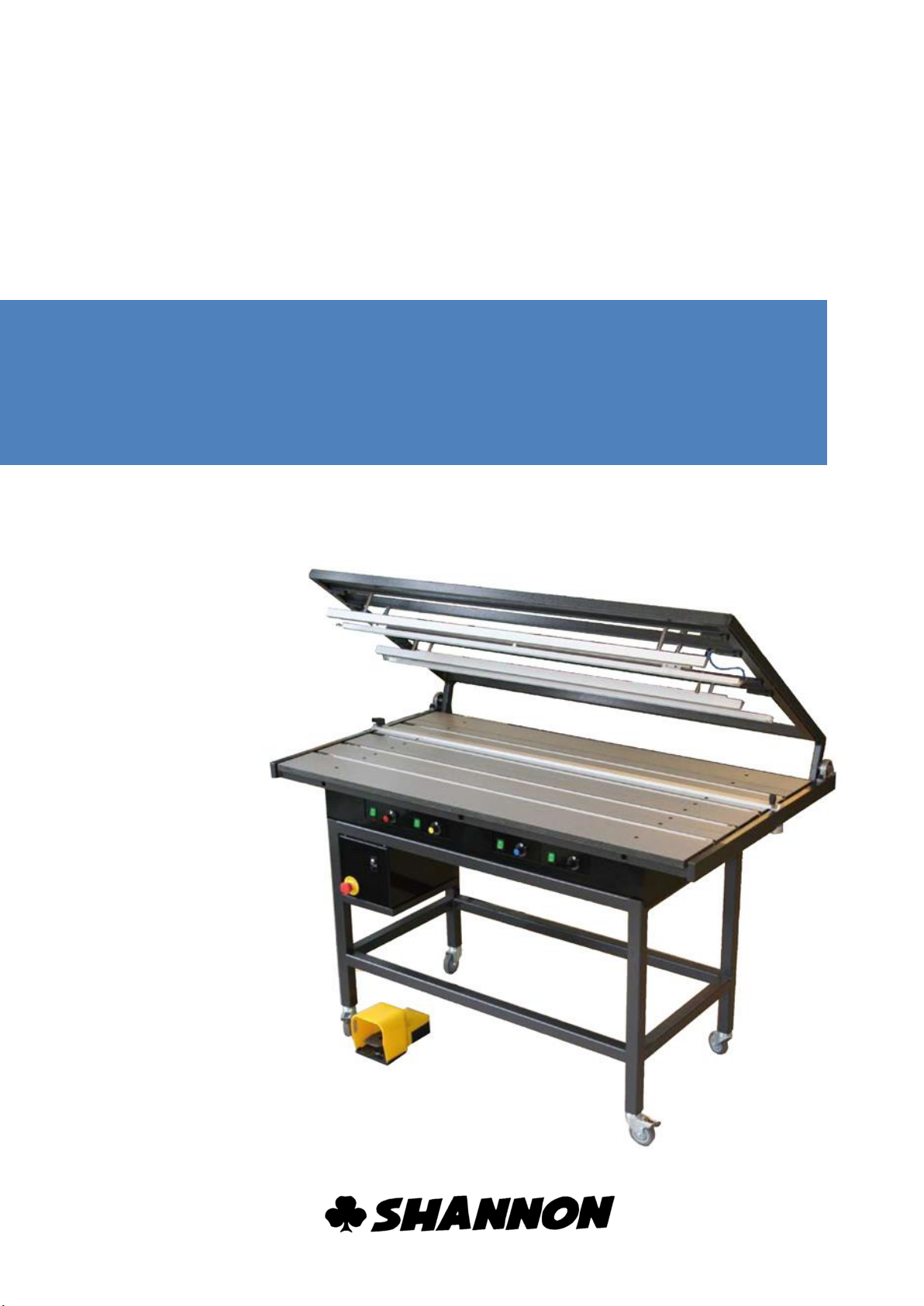
Plastic bending machine
HRK 65-125

User’s guide
HRK 65-125
-1-
HS
User’s guide
Plastic bending machine
HRK 65-125
2013 SHANNON BV. All right reserved.
No part of this User's Guide may be photocopied,
altered or translated without prior written consent.
Information contained in this User's Guide is subject to
change without notice

User’s guide
HRK 65-125
-2-
HS
Contents
Contents 2
Introduction 4
1 Description of the machine 5
2 Technical data 6
3 Safety 7
4 Safety instructions 9
4.1 Emergency stop 9
4.2 Only use the emergency stop when: 9
5 Legend 10
5.1 Summary 10
5.2 Air/timer unit 11
5.3 Timerunit 11
5.4 Control units 12
6 Installation 13
6.1 Assembly 13
6.2 Connecting air/timerunit 13
6.3 Connecting foot switch 13
6.4Connecting compressed air 13
6.5 Connecting power 13
7 Operation 14
7.1 Preparation 14
7.2 Switching on control units 14
7.3 Setting temperature 14
7.4 Trouble shooting 14
7.5 Setting cycle time 15
7.6 Foot switch 15
7.7 Setting air pressure 15
8 Adjustment 16
8.1 Safety precautions 16
8.2 Lower heating element 16
8.3 Upper heating element and pressure bar 17
8.4Lower filament height 17
8.5 Upper filament height 18
8.6Stop 18
9 Maintenance 19
9.1 Safety precautions 19
9.2 Lubrication points 19
9.3 Profiles 19
9.4Water separator 19

User’s guide
HRK 65-125
-3-
HS
Contents
10 Tensioning and changing filament 20
10.1 Safety precautions 20
10.2 Tensioning 20
10.3 Changing the filament 21
11 Fuses 22
11.1 Safety precautions 22
11.2 Fuses control units 22
Annex 23
A Options 23
Accessories 23
Equipment 23
B Service and warranty 25

User’s guide
HRK 65-125
-4-
HS
Introduction
Congratulations on purchasing Shannon’s plastic bending machine HRK 65-125. Red this
guide completely before installing and using the machine.
We want to keep in contact and to know how you find the HRK 65-125. We are always
willing to advice on the use of the machine and its accessories.
SHANNON BV
Turfschipper 11-13
2292 JC Wateringen
Postbus 84
2290 AB Wateringen
Nederland (EC)
Tel. +31 (0)174 225240
Fax. +31 (0)174 225249
E-mail: [email protected]
Website: www.shannon.nl

User’s guide
HRK 65-125
-5-
HS
Description of the machine
The Shannon HRK bending machine is a rapidly convertible semi-automatic machine for
the production of large series of items with multiple bends for the plastic sheet processing
industry.
oThe machine has four adjustable heating elements as standard. Four reflectors
under or two under and two upperreflectors. The temperature of which can be
adjusted independently by electronic controls.
oThe filaments of the heating elements on the working surface are adjustable in
height. The other elements, which are mounted in the pneumatically operated top
frame which clamps the workpiece in place, are adjustable in height as a single
unit in respect of the working surface.
oThe workpiece can be heated from two sides, considerably reducing the
production cycle time and making it possible to bend sheet up to 6 mm thick.
oThe top frame is switched on independently of the control units and is controlled
by an adjustable timer.
oThe working surface is made of scratch-resistant solid core material with which
the space between the zones to be heated can be filled to support the plastic
sheet.
When heated, thermoplastics become so flexible that
they can be shaped. When a plastic sheet is heated to
its softening point in a narrow zone, if can be bent to
any angle desired.
The bending radius is determined by the width of the
heated zone. The zone is determined by the thickness
of the material, the type of heating element and the
distance between the plastic and the filament.
Every plastic has its specific softening point. By coordinating the temperature, heated
zone and the heating time all kinds of thermoplastic can be processed.
1
User’s guide
HRK 65-125
-6-
HS
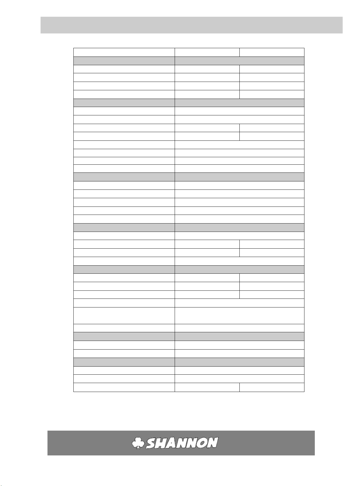
Technical data
type
HRK 65
HRK 125
Assembly
Control unit
Max.
2x DB
4x DB
Upper heating element
Max
2
4
Lower heating element
Max
4
4
Pressure bars
2
4
Electrical
Control unit
Voltage
220 –240 V AC
Power
300 VA / 500 VA / 1000VA
Fuse
2,5 AT x2
5 AT x2
max. power:
1000VA
4000 VA
connection
CEE 7/4 16A 2P+A
Filament
0-30 V, 0-13 A ~
Network connection
CEE 7/4 16A 2P+A
Network circuit breaker
Max. 16 A
Pneumatic
Air
Unlubricated clean dry air
Maximum
6 bar
Minimum
5 bar
Operating pressure
6 bar
Coupling
Quick action coupling
Mechanical
Gradation of stop
0-500 mm
dimensions
[LxWxH]
860 x 750 x 380 mm
1470 x 850 x 275 mm
weight
85 Kg
120-140 kg**
Lifetime filament
±500 hour
Functional
Bending width
650 mm
1250 mm
Mutually extendible*
10-465 mm
10 - 610 mm
Sheet thickness*
1 - 10 mm
1 - 20 mm
Temperature filament
Max
20-600 ◦C
Filament height
adjustment
Bottom
1 - 6 mm
Top
6 - 25 mm
Ambient
Temperature
18-30 C
Humidity of the air
50-80 % (no condensed)
Miscellaneous
set of socket screws keys
1 set [1½, 3, 5 mm]
Spare fuse
2 x [6.3x32 5 AT] each controller
Spare filament
1 x [0.9 x 750 mm]
1 x [0.9 x 1350 mm]
* Depends on the heating element
** Depends on the amount of controllers
2
User’s guide
HRK 65-125
-7-
HS
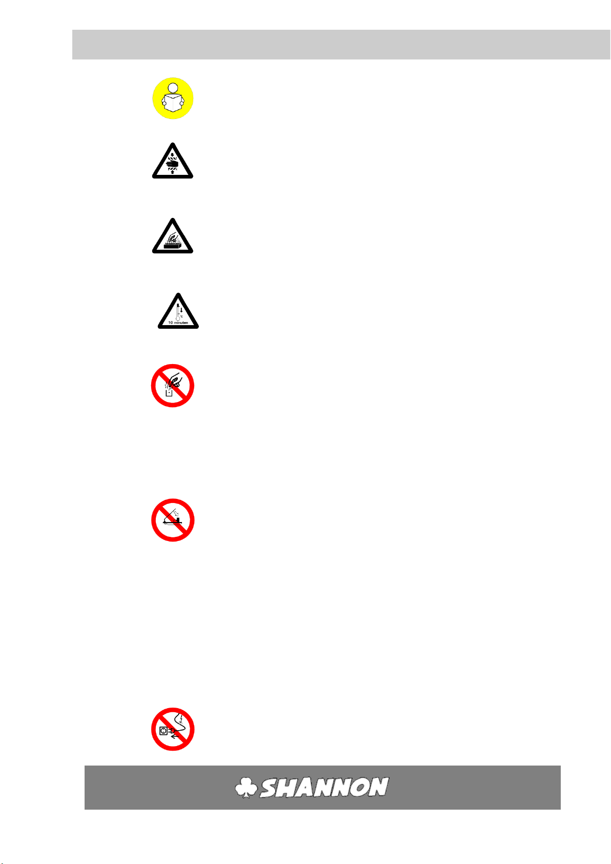
Safety
To ensure safety when using the machine you should read this
User's Guide carefully and follow the safety instructions closely
Attention!
The machine contains a section where there is a risk of
trapping.
Attention!
The machine contains parts, which are hot. Touching them will
cause burns.
Allow hot parts to cool sufficiently (at least 10 minutes) before
touching them.
Never touch the filaments or the reflectors when the machine
is in operation.
Always wear close-fitting clothing.
Be particularly careful of sleeves and always tie back long hair.
Never leave objects on the working surface.
The machine may only be used for heating narrow zones in flat
plastic sheet.
Any other use could lead to very hazardous situations or cause
damage to the machine!
The plastic sheets that have to be bent may never be thicker
than 6 mm.
Before commissioning and servicing always check the
connection cable and plug for defects.
3

User’s guide
HRK 65-125
-8-
HS
When servicing switch off the machine and remove the plug
from the socket.
Before use always check that all the pressure bars and heating
elements in the top frame are firmly attached.
Only switch on those heating elements which are needed.
Never operate the machine if anyone is standing close behind
or beside it.
Never introduce objects or material into the machine from the
rear.
Never leave the machine unattended without switching it off.

User’s guide
HRK 65-125
-9-
HS
Safety precautions
4.1 EMERGENCY STOP
There is an emergency stop button (C) at the front of the air/timer unit, which can be
reached by the operator from the normal working position.
Pressing the emergency stop button switches off the timer and the top frame lifts up. The
button remains pushed in.
Resetting of the emergency button comes to pass by turning the button to the right.
The machine is ready to use again.
4.2 ONLY USE THE EMERGENCY STOP BUTTON WHEN:
oRisk of trapped limbs.
oDefects in the timer, so the machine fails to open after the pre-set time.
oAn outbreak of fire or situations involving a risk of fire.
oAny situation that might present a risk to people or animals.
oAny other situation, that might present a risk or cause, damage to the machine
and/or objects.
4
User’s guide
HRK 65-125
-10-
HS
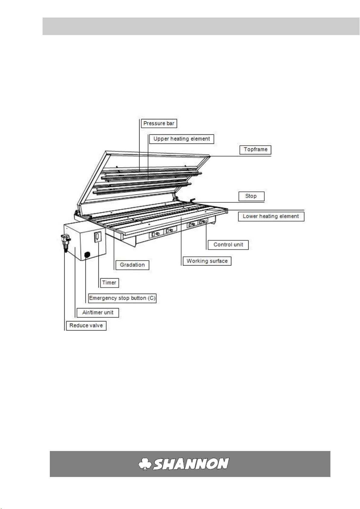
Legend
5.1 SUMMARY
The legend of the entire machine
5

User’s guide
HRK 65-125
-11-
HS
Legend 5
5.2 AIR/TIMER UNIT
The air/timer unit is a combined unit for the control of the
topframe and to set the cycle time.
The machine closes, when the foot switch is used. The
timer will start when the machine is proper closed. The
machine opens again when the time reached its value. The
timer will reset back to zero
A. Connection foot switch
B. On/off switch
C. Emergency button
D. Timer unit
5.3 TIMER UNIT
There are three numbers on the screen. From E to G the number means:
E. The time that the machine will buzz
F. The time that the machine is closed. The time will start when the machine is
entirely closed.
G. The time till the machine opens again.
Button
Function
Esc
cancel
+
increase value
-
decrease value
OK
confirm
►
move right
▼
move down
▲
move up
◄
move left
F
E
G
A
C
B
D
User’s guide
HRK 65-125
-12-
HS
Legend 5
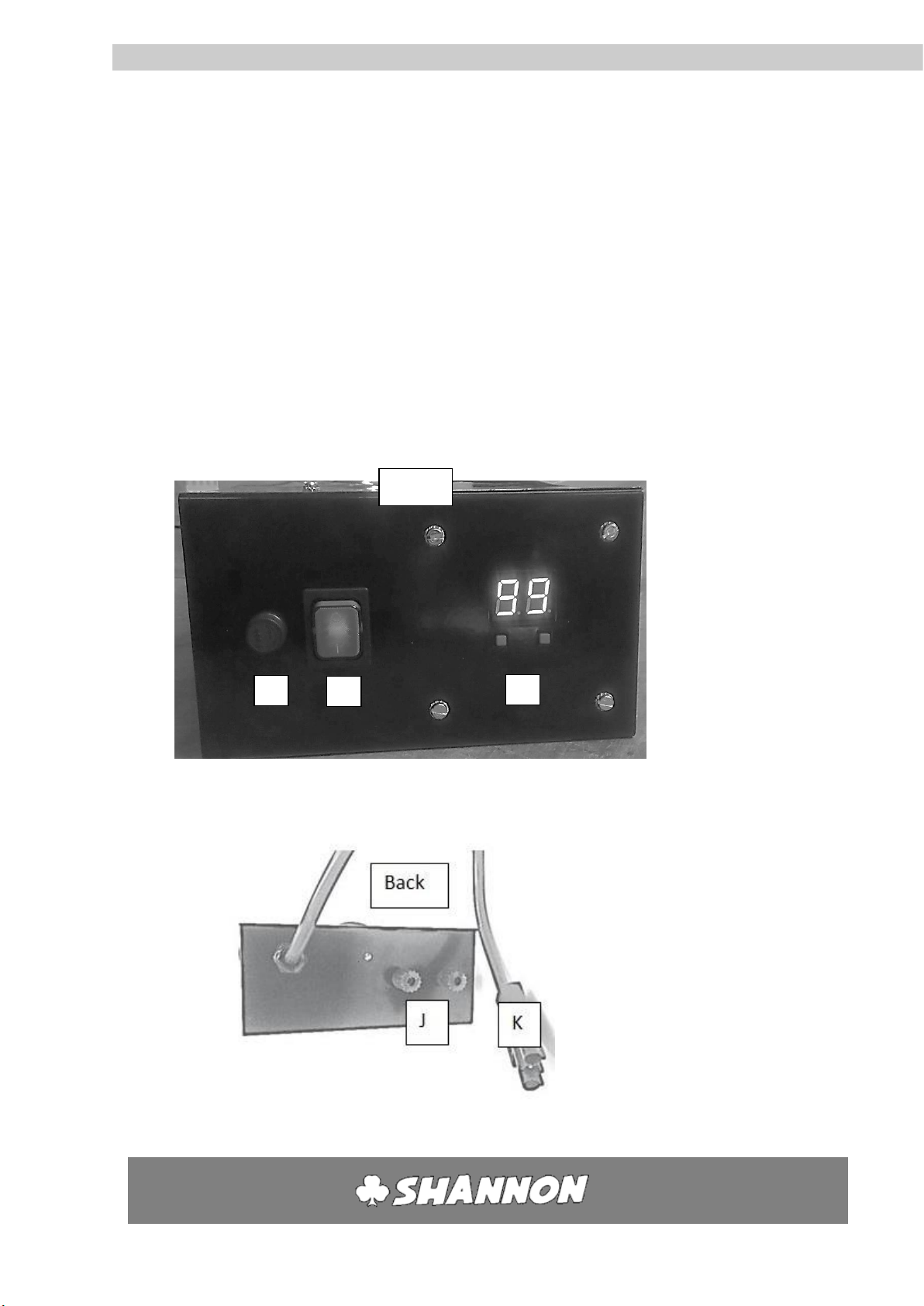
5.4 CONTROL UNITS
The control unit contains an electronic controller that can be used to set the temperature of
the filament
H. On/off switch
I. Temperature adjustment
J. Connection to filaments
K. Connection to 220 V AC
L. Fuse
H
L
I
FRONT

User’s guide
HRK 65-125
-13-
HS
Installation
6.1 ASSEMBLY
1. Remove packaging and blocking of top frame.
2. Place the machine on a level floor with sufficient space around and above the
machine.
3. Ensure there is adequate ventilation and lighting at the workplace.
4. Avoid draughts, in order to prevent uneven heating.
6.2 CONNECTING AIR/TIMER UNIT
A black tube that is coming out of the machine has one air tube. Connect the tube to the
corresponding number of the air/timer unit (at the backside).
6.3 CONNECTING FOOT SWITCH
Connect the plug of the foot switch on the corresponding socket (a) at the front side of
the timer unit. See 5.2
6.4 CONNECTING COMPRESSED AIR
1. Check that all heating elements and pressure bars in the top frame are firmly
attached.
2. Using a quick-action coupling connect the rear of the machine to your compressed
air system or compressor.
6.5 CONNECTING POWER
1. Check that all switches of the control units are in the 0-position.
2. Put the plug into the socket.
6

User’s guide
HRK 65-125
-14-
HS
Operation
7.1 PREPARATION
1. Check that the air pressure is connected
2. Clear the working surface
3. Check that all the heating elements are connected to the control units.
4. Check that no scraps of material remain in the reflectors.
5. Check that all the upper heating elements and pressure bars are firmly attached
to the top frame.
7.2 SWITCHING ON HEATING ELEMENTS
Each heating element can be switched on and controlled individually.
1. Switch on the desired control unit with switch (H). See 5.4
7.3 SETTING TEMPERATURE
The temperature of the filament can be set using the temperature control.
1. When turning on the on/off switch, the display will show the value that was last saved
(keeping the machine on a certain value for >20 seconds will make it remember this
value).
2. Press the right button (arrow up) to increase the value, up to 99 (keeping this pressed in
will make the value cycle much faster)
3. Press the left button (arrow down) to decrease the value, down to 00 (keeping this
pressed in will make the value cycle much faster)
4. Press both buttons at the same time to go directly to 00. Doing this also resets the
machine.
7

User’s guide
HRK 65-125
-15-
HS
Operation 7
7.4 TROUBLE SHOOTING
7.5 SETTING CYCLE TIME
The time during which the machine is closed to heat the plastic sheet on two sides can be set
on the timer unit.
At first use of the machine, set E = 5 and F = 20 (See 5.3)
1. Switch between values with the ▼/▲buttons.
2. Increase or decrease the value with the +/- buttons.
3. Cancel the value with the “ESC” button.
4. Confirm the value with the “OK” button.
7.6 FOOT SWITCH
The top frame is served by pressure on the pedal of the foot switch.
7.7 SETTING AIR PRESSURE
The pressure for the system is adjusted by the factory on the right value (6 bar)
Error message
Meaning
Solution
E1
The wire is loose (not connected)
Turn off the machine, check the filament, and reset the
machine
(see §9.1 for changing filament)
Note: Between the values 00 and 04, this fault cannot be
detected
E2
The wire is loose (spark detection)
Check the connection of the filament
Check the filament, and reset the machine
This fault can also be reset by the arrow down button
(see §9.1 for changing filament)
E9
Broken circuit board
Contact the supplier for a new circuit board
Empty display
No power
Alert a maintenance engineer
Check the fuse (see §10.1)
Check the power supply cable
Contact the supplier if necessary

User’s guide
HRK 65-125
-16-
HS
Adjustment
8.1 SAFETY PRECAUTIONS
Always take the following safety precautions before adjusting the heating elements:
1. ensure that the upper heating element and pressure bars are firmly attached
2. Switch off the heating elements one by one (Switch H).
3. Clear the working surface
4. Allow the heating elements to cool for at least 10 minutes
8.2 LOWER HEATING ELEMENT
1. Remove the strips of solid core material next to the
heating element to be adjusted by loosening the two
socket head screws (use socket screw key no. 5).
2. Loosen the socket head screws in the supporting
prongs on the left and right of the heating element, one
half turn.
3. Loosen the socket head screw in the centre of the
heating element one half turn
(use socket screw key no. 3).
4. Take the heating element with both hands close to the
supporting prongs on the left and right and slide it into
the desired position.
5. Hold the heating element parallel to the front of the
machine and the supporting prongs. This prevents the
notched nuts in the X-profiles from binding.
6. Hand tighten the socket head screws, starting in the
supporting prongs and then in the centre.
7. Position the other profiles in the same way if
necessary.
8. Fill up the space between the heating elements as far
as possible with solid core strips and hand tighten
them. First slide the notched nuts into the aluminium
X-profiles, roughly level with the holes and then lay the
solid core strip on top.
9. Switch on the machine again as in Section 7.
8

User’s guide
HRK 65-125
-17-
HS
Adjustment 8
8.3 UPPER HEATING ELEMENTS AND PRESSURE BAR
1. Disengage the air connection
2. The top frame will then slowly lower while air escapes
3. Loosen the socket head screws on the support bar clamps one turn
4. Hold the heating element at the sides, left and right, and slide it into the desired
position. Move the support bar parallel to the front of the top frame, so that you
position the top filament above the bottom one.
5. Tighten the support bar clamps again.
6. Switch on the machine again as in Section 7.
The upper heating elements and pressure bar may fall out of the top frame if they are loose
or not properly attached.
8.4 LOWER FILAMENT HEIGHT
1. Adjust the height of the filament using the knurled nut. These can be reached from
the sides. Make sure that the filament height is the same on both sides.
2. Start up the machine again as in Section 7.
8.5 UPPER FILAMENT HEIGHT
Make sure that the lower and upper heating elements and the pressure bars are in the
correct position.
1. Set the timer (D) to at least 60 sec. (6x10)
2. With this time setting the machine will remain
closed for long enough to adjust the filament
height.
3. Place a test piece of the plastic to be processed
on the working surface
4. Lower the top frame (foot switch)
5. Adjust the height of the filament using the
adjusting nuts on the upper heating elements
6. You can set the filaments to a minimum of 6 mm
above the plastic
7. Adjust the height so that the element is clear of the plastic
8. Open the top frame by pressing the emergency stop (C)
9. Reset the emergency stop
10. Adjust the timer (D) again
11. Start the machine again as in section 7.

User’s guide
HRK 65-125
-18-
HS
Adjustment 8
8.6 STOP
1. Loosen both the handles on the stop one half turn
2. Slide the stop into the desires position
3. Hold the guide parallel to the front of the machine. This stops the clamping
blocks from binding
4. Tighten the handles
Always ensure that the stop is placed in such a way that heating elements or pressure bars
cannot hit the stop as they are lowered.

User’s guide
HRK 65-125
-19-
HS
Maintenance
This machine needs little maintenance. Remove loose dirt once in a while.
9.1 SAFETY PRECAUTIONS
1. Switch of all regulating units (switch H)
2. Clear the working surface
3. Disengage the air connection
4. Remove the plug from the socket
9.2 LUBRICATION POINTS
The following points should be lubricated with a drop of oil or grease once a year:
1. Bearing cylinder: underside (The lubrication point can be accesses from the rear
of the machine.
3. Bearing cylinder: upperside (The lubrication point can be reached by removing
the solid core strips on the middle of the machine.
9.3 PROFILES
The heating elements work more effectively when they are clean. Remove dirt and deposits
from the heating elements regularly. Blow away loose dirt and brush them clean.
9.4 WATER SEPARATOR
Check if there is water in the water separator and remove it if necessary. The water
separator is situated on the left of the air/timer unit. If there is water in the flass holder, it
should be drained off.
1. Disengage the air connection
2. The top frame will lower slowly
3. Hold a container under the nipple and slowly open the nipple. All the water will
then run out of the glass holder
4. Close the drain nipple by hand
5. Switch the machine on again as described in section 7.
9
This manual suits for next models
1
Table of contents
Other Shannon Cutter manuals

Shannon
Shannon HRT/D 300 User manual

Shannon
Shannon HRT 65 User manual

Shannon
Shannon HR 220-300 User manual

Shannon
Shannon HRP/S User manual

Shannon
Shannon AFF/D 135 User manual

Shannon
Shannon HRP 220 User manual

Shannon
Shannon HRT 220 User manual

Shannon
Shannon HRP/D User manual

Shannon
Shannon ABM-D 135 User manual
Popular Cutter manuals by other brands


YATO
YATO YT-82158 Original instructions

UTILCO
UTILCO UM-25 instruction manual

Alfa Network
Alfa Network SVAROG 125 PLASMA Operating and maintenance instructions

Timco Tools
Timco Tools NL30CUT Operation manual

Constructor
Constructor CTC601-180 Original instructions

Full Boar
Full Boar FBT-8800 instruction manual


