11
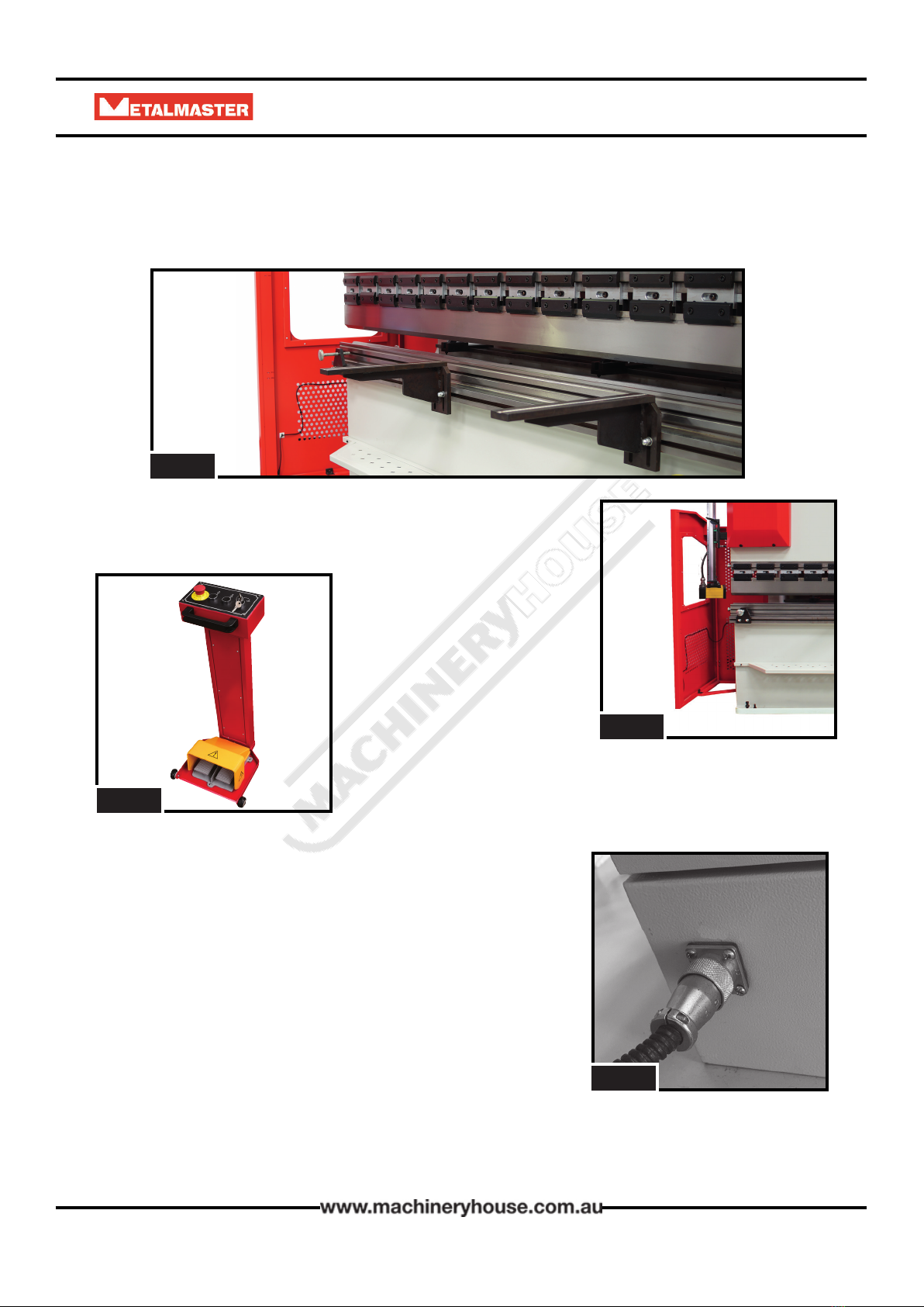
OPERATION MANUAL PB-CL SERIES
2.2 HYDRAULIC PRESS BRAKE SAFETY PROCEDURE
DO NOT use this machine unless you have been instructed in its safe use and
operation and have read and understood this manual
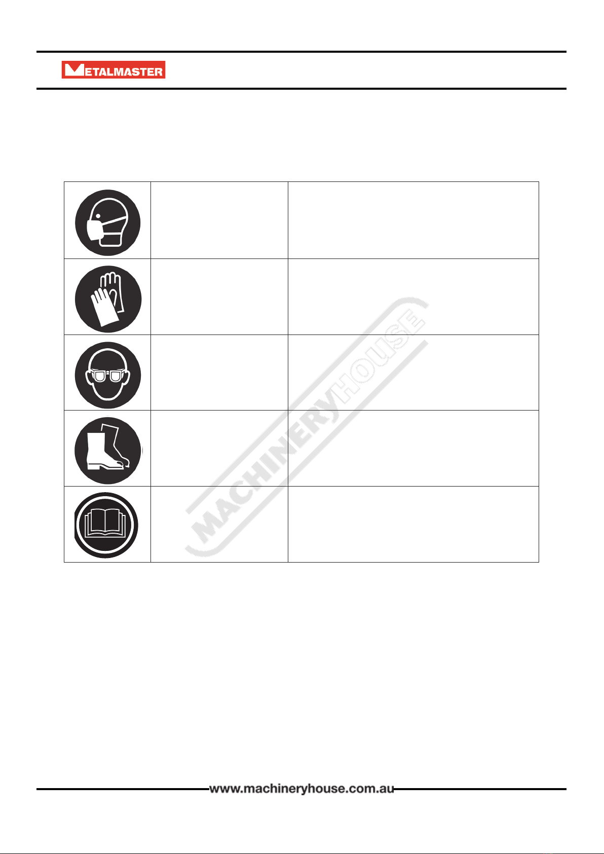
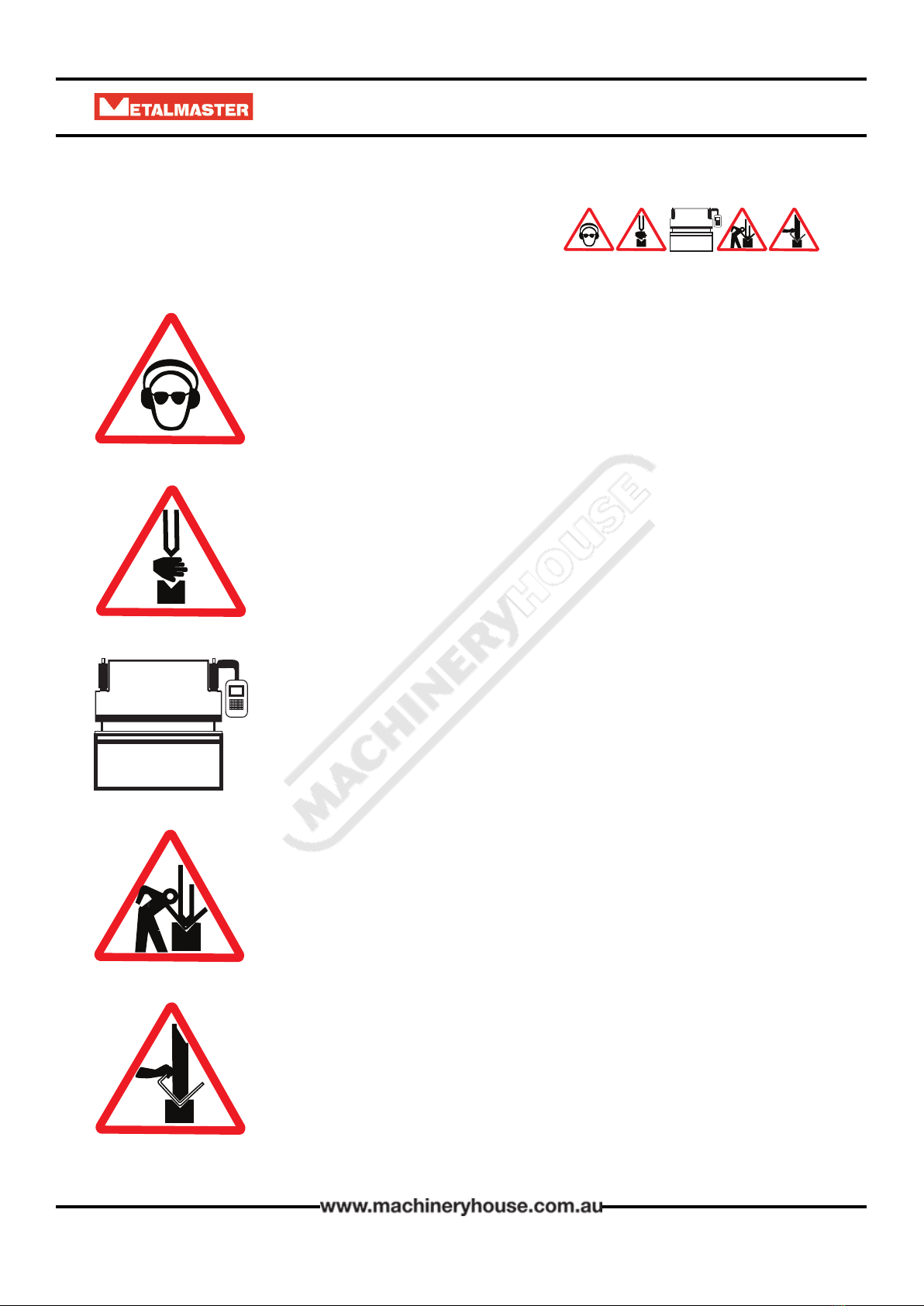
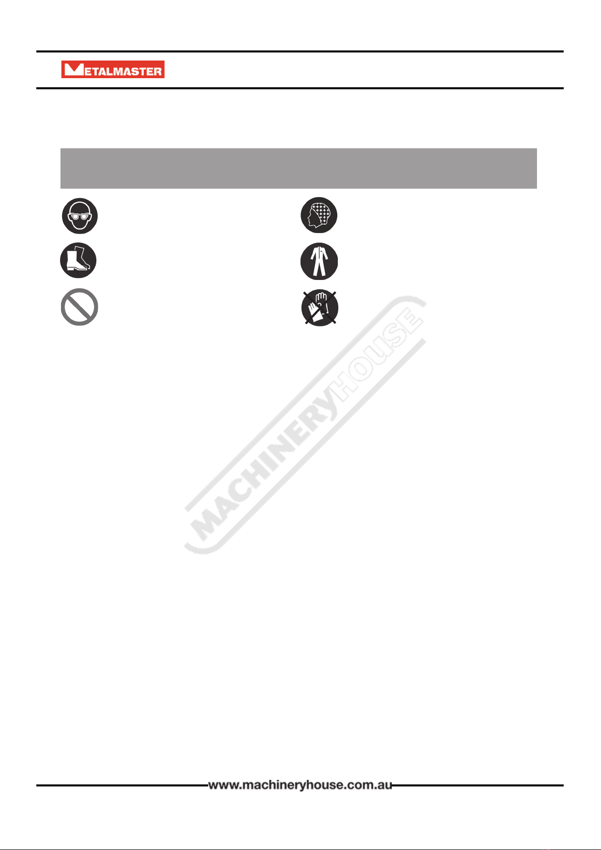
Long and loose hair must be
contained or restrained
Safety glasses must be worn at all
times in work areas.
Appropriate protective footwear with
substantial uppers must be worn
Coveralls, protective clothing, or a
workshop apron, is recommended
Rings and jewelery must not be worn. DO NOT wear large leather gloves
when operating this machinery
PRE-OPERATIONAL SAFETY CHECKS
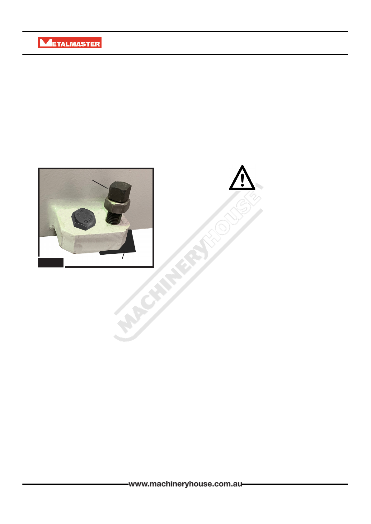
1. Ensure that all guards and safety devices are in position and secured.
2. Adjust all guards to minimum practicable clearances for the material to be pressed.
3. Note: any guards and safety devices should NEVER be removed, except for maintenance
purposes, and only by an authorised sta member.
4. Working parts should be well lubricated and all jaws, ngers, ‘V’ blocks and blades be free of
rust and other foreign matter.
5. Adjust the head rams to suit the material thickness.
6. Adjust and check that the‘v’ forming blocks and/or knife blades are aligned correctly.
7. Be aware of any other personnel in the immediate vicinity and ensure the area is clear
before using this equipment.
8. Familiarize yourself with all electrical, hydraulic and mechanical operations and controls,
including the roving foot pedal control.
OPERATIONAL SAFETY CHECKS
1. Strictly only one operator is to use this heavy duty press brake, and, when necessary, with a
safety observer present.
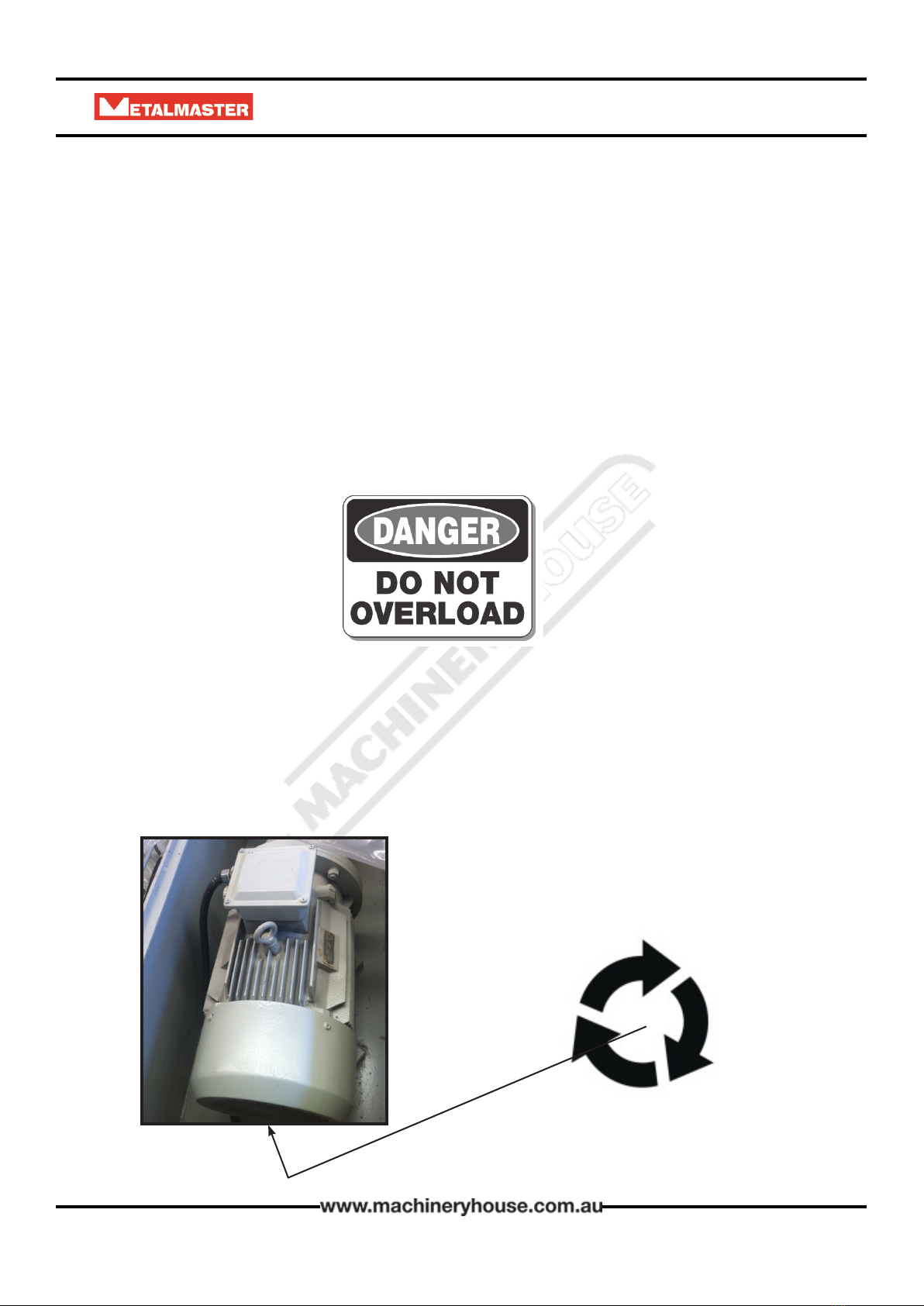
2. Never use any press or pan brake to bend or fold beyond the capacity of the machine.
3. Ensure that both hands are positioned away from any possible pinch point
4. Particular preparation and caution is to be observed when bending rod, strap or spring
steel.
5. This heavy duty press brake is likely to be tted with infra-red safety beams or electronic
sensors to detect hazardous circumstances. If so, this machine should NOT operate if these
safety devices are breached in any way, either by materials or by the operator.
6. Never leave the machine in operational mode while unattended.
POTENTIAL HAZARDS
Entanglement and entrapment Striking and shearing
Pinch, crush and squash Manual handling
Electrical and hydraulic components Eye injury