FISCHBEIN Empress Series User manual
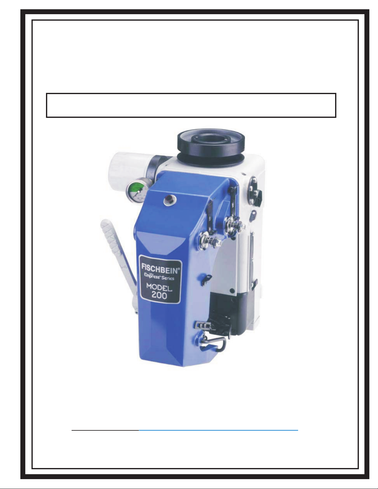
EMPRESS SERIES
Model 200 and 201 Sewing Heads
FISCHBEIN
B A G C LO S I N G
®
OPERATOR’SMANUAL
®
Rev. C 2013-06
Part No. 37075
Featuring Short Stroke Technology ©

FISCHBEIN
®
MODELS 200 & 201 EMPRESS
®
SEWING HEAD
(Short Stroke
Technology)
OPERATOR’S MANUAL
REV. C 2013-6
1
TABLE OF CONTENTS
Page
Corporate Statement………………………………………………………………… 3
1. Introduction…………………………………………………………………………. 4
1.1 System Description………………………………………………………….. 4
1.2 Warnings………………………………………………………………………… 5
1.3 Characteristics…………………………………………………………………. 6
2. Installation…………………………………………………………………………… 8
2.1 Unpacking Procedures……………………………………………………… 8
2.2 Drive motor recommendations………………………………………….. 8
2.3 Mounting the Sewing Head……………………………………………….. 9
2.4 Lubrication……………………………………………………………………… 11
2.5 Maintenance……………………………………………………………………. 12
2.6 Start up recommendations………………………………………………… 13
2.7 Consumables…………………………………………………………………… 13
3. Machine Adjustments………………………………………………………… 15
3.1 Threading the sewing head………………………………………………..15
3.1.1 Needle and Looper Thread…………………………………15
3.1.2 Filler Cord (Optional) ………………………………………..16
3.2 Thread tension adjustment…………………………………………………17
3.3 Stitch length adjustment…………………………………………………… 19
3.4 Cork seal replacement……………………………………………………….20
3.5 Needle replacement…………………………………………………………..21
3.6 Feed dog replacement……………………………………………………….21
3.7 Throat plate replacement…………………………………………………..22
3.8 Presser foot pressure adjustment………………………………………. 22
3.9 Fine tuning of the sewing machine……………………………………..23
3.9.1 Presser foot adjustment……………………………………. 23
3.9.2 Needle and needle guide adjustment…………………. 23
3.9.3 Needle and looper clearance…………………………….. 24
3.9.4 Distance between needle and looper…………………. 25
3.9.5 Needle and looper eyelet alignment…………………… 25
3.9.6 Feed dog height adjustment……………………………… 26
3.9.7 Feed dog and throat plate clearance…………………..28
3.9.8 Needle chuck adjustment…………………………………..28
3.9.9 Outside Needle Guide adjustment…………………….. 29
3.10 Tape/Thread Clipper Adjust (model 201 only) …………………… 30
3.11 Installing new blades (model 201 only) ……………………………. 31
3.12 Mounting & Adjusting the Rotary Air Knife (model 200 only)….33
3.13 Using the Gauge………………………………………………………………. 36
3.14 Sewing speed adjustment and synchronization…………………….37
3.14.1 Calculating conveyor speeds……………………………… 37

FISCHBEIN
®
MODELS 200 & 201 EMPRESS
®
SEWING HEAD
(Short Stroke
Technology)
OPERATOR’S MANUAL
REV. C 2013-6
2
TABLE OF CONTENTS
Page
3.14.2 Bag handling capacity………………………………………. 38
3.14.3 Synchronizing the sewing system………………………. 39
4. Speed tables…………………………………………………………………………42
4.1 English System………………………………………………………………….42
4.2 Metric System……………………………………………………………………43
5. Opening a sewn bag…………………………………………………………….44
6. Troubleshooting……………………………………………………………………45
7. Spare Parts List…………………………………………………………………….59
8. Drawings and Parts Lists……………………………………………………50
9. Machine Set Up Parts Lists………………………………………………..82
9.1 Model 200……………………………………………………………………… 82
9.2 Model 201……………………………………………………………………… 83
10. Safely Disposing of a Sewing Head……………………………….. 83

FISCHBEIN
®
MODELS 200 & 201 EMPRESS
®
SEWING HEAD
(Short Stroke
Technology)
OPERATOR’S MANUAL
REV. C 2013-6
3
READ
READ THIS MANUAL BEFORE INSTALLING, OPERATING
OR PERFORMING MAINTENANCE ON THE MODEL 200 OR
201 EMPRESS
®
SEWING HEAD.
CORPORATE STATEMENT
The Fischbein Company is a premier packaging company that specializes in
bag closing systems. The original one-man business, founded and established by Dave
Fischbein in Minneapolis, Minnesota in 1910, has now grown to an international firm
recognized as the global leader in bag closing technology which manufactures a variety
of state-of-the-art bag closing and handling machines for diverse packaging
applications. Fischbein’s first portable sewing machine for bag closing was developed
over 50 years ago and is still widely used throughout the world for a variety of bag
closing applications. Through our bag sewing, closing and sealing technologies,
Fischbein offers automated solutions for nearly every powder and bulk material
packaging requirement.
The product line has greatly expanded from those early days, and the company
continues to lead the industry in helping customers increase productivity through
improved product performance with efficient, up-to-date automated packaging solutions.
A worldwide network of distributors assists our customers in meeting their
technological requirements and their business objectives. Orders, questions and
comments can be addressed to Fischbein through the worldwide web at
www.fischbein.com or by writing or calling our North American or European offices:
North American Office Main European Office
Fischbein Company Fischbein SA
151 Walker Road Paepsem Business Park
Statesville, NC 28625 Boulevard Paepsem 18B
Phone: (704) 871-1159 1070 Brussels, Belgium
FAX: (704) 872-3303 Phone: 011-322-555-1170
FAX: 011-322-520-3390

FISCHBEIN
®
MODELS 200 & 201 EMPRESS
®
SEWING HEAD
(Short Stroke
Technology)
OPERATOR’S MANUAL
REV. C 2013-6
4
1. INTRODUCTION
The contents of this manual are considered to be proprietary and
confidential to FISCHBEIN AND ARE NOT TO BE REPRODUCED WITHOUT
PRIOR WRITTEN PERMISSION FROM FISCHBEIN.
Nothing contained in this document is intended to extend any promise, warranty
or representation, expressed or implied, regarding the FISCHBEIN products described
herein. Any such warranties or other terms and conditions of products shall be in
accordance with the standard terms and conditions of sale for such products, which
are available upon request.
FISCHBEIN reserves the right to make changes and improvements to products
without notice and without incurring any obligation to make such changes or add such
improvements to products sold previously.
The use of repair parts other than those included within the FISCHBEIN
approved parts list may create hazardous conditions over which FISCHBEIN has no
control. Therefore, FISCHBEIN cannot be held responsible for equipment in which
non-approved repair parts are installed.
1.1 SYSTEM DESCRIPTION
The Fischbein 200 and 201 short stroke sewing heads are heavy duty, commercial
sewing machines. The shorter stroke means the sewing head has less vibration and
the needle follows a more precise path to the bag. In order to identify short stroke
models, the letters “HS” will follow the sewing head’s serial number. These heads sew
bags of different materials, such as plastic, woven polypropylene, multi- wall paper
bags, composite bags, jute bags and so forth.
For proper operation, these heads are normally mounted on Fischbein double
pedestal stands and conveyor systems. These enable adjustment of the system for
bag height and bag speed through the system. A variety of infeeds and other special
attachments (such as a rotary knife and a needle cooler) are available to enhance and
support the operation of the head.
Model 200 S
This model is intended for standard sewing, two-thread applications.
Model 200 DCS
Same as standard head with rotary knife at 24VDC.
Model 200 NKS
Same as 200 standard head, but without any knives.
Model 201 S
This model is intended for standard sewing, two-thread applications with crepe tape.
Model 201 TCS
Same as 201, but can be used with or without crepe tape.

FISCHBEIN
®
MODELS 200 & 201 EMPRESS
®
SEWING HEAD
(Short Stroke
Technology)
OPERATOR’S MANUAL
REV. C 2013-6
5
1.2 WARNINGS
•The model 200 and 201 sewing heads are driven by strong motors, contain moving
parts and have pinch points and sharp edges. Therefore, a certain amount of technical
knowledge and familiarity with this type of equipment are required to operate and
maintain the system. Proper eye, hand and foot protection must be worn while working
with the 200 and 201 sewing heads.
•The sewing head is not a stand-alone machine; therefore, care must be taken to
provide the correct drive system and proper protection from the drive components. You
should follow the recommendations in the manual about the drive system.
•Read the manual carefully before making any changes to the sewing head.
•Replacement of the Connecting Needle Drive Rod (pages 54-57; Item 20: part #31056)
and the bushings for the main shaft (page 66-67) must be performed by an authorised
Fischbein representative, equipped with the special tools necessary.
•Always use genuine Fischbein spare parts (including Fischbein Lubricating Oil
and Fischbein Oil Filters). Our parts are specifically designed for Fischbein
equipment to provide optimum performance and safety. Use of non-Fischbein
parts can also void product warranty.
•Turn off and lock out air and power sources when performing maintenance.
•Let the machine do the work. Do not pull the bag or the materials through it.
•Consult Fischbein concerning your specific application and sewing need.
•The sewing head is not suitable to operate in an area where explosive materials are
present (explosive gas, vapors, powders or liquids). When used in a dusty
environment, NEMA 12 (IP54) electrical equipment must be used.
•Frequently clean the machine to prevent accumulation of dust. Do this to prevent
accumulation of debris that may cause a fire or malfunction.
•Any sources of leaks of the machine’s lubricating oil must be repaired immediately to
prevent possible contamination of the product being packed and safety hazards around
the system.
•
When cleaning the sewing head, use only recommended Fischbein cleaning solvent 5-
101.
•
Do not use aggressive cleaning products as they may damage the rubber seals.
•
When in doubt about operation, troubleshooting and maintenance of the sewing head,
consult your dealer or local Fischbein representative.
•Other specific warnings appear throughout this manual.
FISCHBEIN
®
MODELS 200 & 201 EMPRESS
®
SEWING HEAD
(Short Stroke
Technology)
OPERATOR’S MANUAL
REV. C 2013-6
6
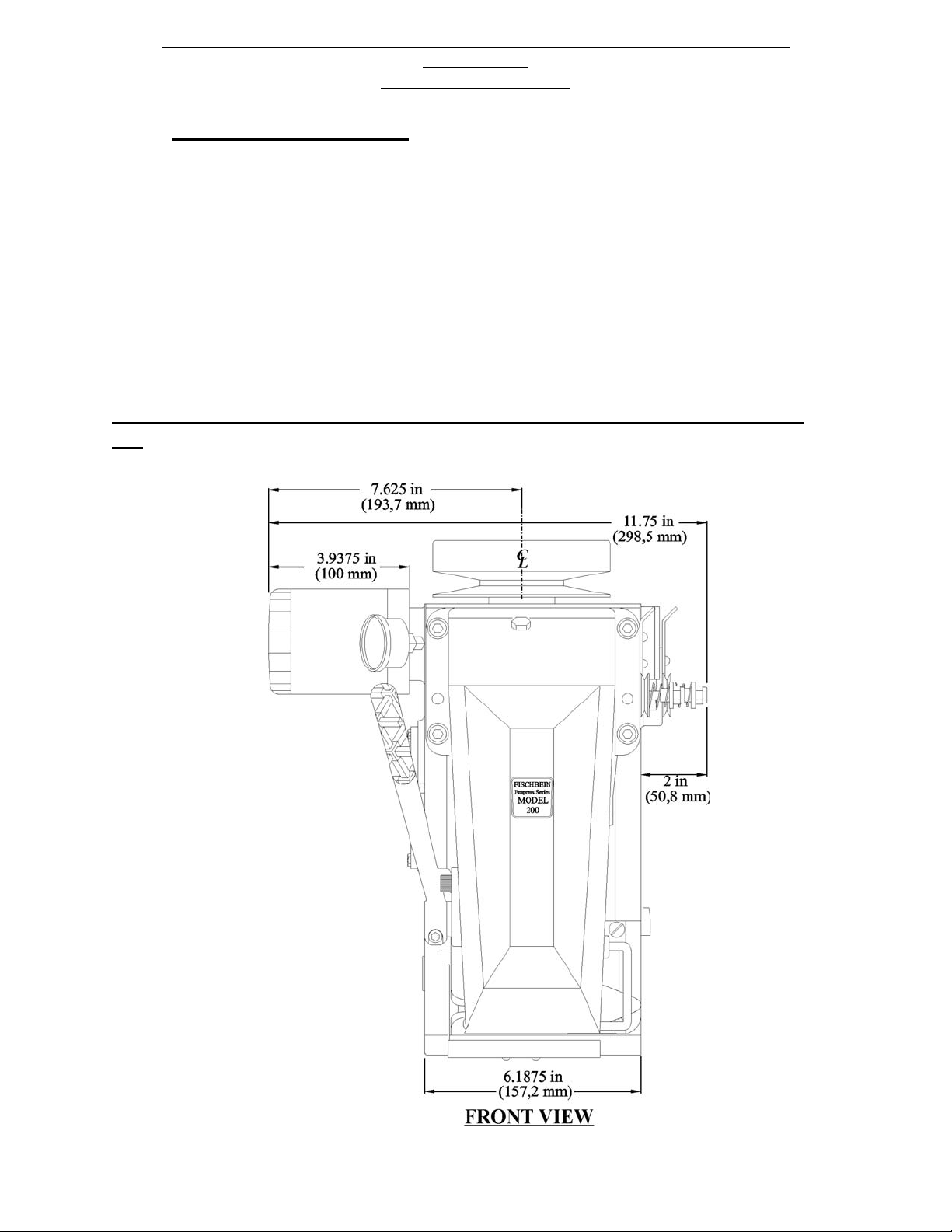
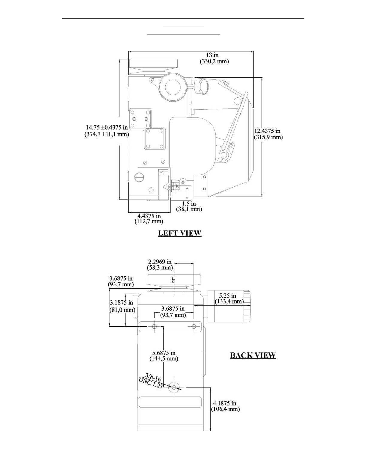
1.3 CHARACTERISTICS
Maximum speed: 2400 rpm
Stitch length: 2 – 3.25 stitches per inch (8 – 12 mm/stitch)
Net Weight: Model 200: 63 lbs. (28,6 kg)
Model 201: 65 lbs. (29,5 kg)
(withTapeClipper)
Shipping Weight: Model 200: 66 lbs. (30 kg)
Model 201: 68 lbs. (30,9 kg)
(withTapeClipper)
Oil: 1 qt (0.95 litres)
Mobil SHC 626 Synthetic Oil
Maximum speed is 2400 RPM. (Refer to Speed Tables, pages 41 and
42)
FISCHBEIN
®
MODELS 200 & 201 EMPRESS
®
SEWING HEAD
(Short Stroke
Technology)
OPERATOR’S MANUAL
REV. C 2013-6
7

FISCHBEIN
®
MODELS 200 & 201 EMPRESS
®
SEWING HEAD
(Short Stroke Technology)
OPERATOR’S MANUAL
REV. C 2013-6
8
2. INSTALLATION
2.1 UNPACKING PROCEDURES
Every Fischbein sewing head is packaged to protect the unit during normal shipping,
storage and handling. Each sewing head is packed in a corrugated box with
cardboard padding surrounding it. It is then taped shut. Before the unit is unpacked,
inspect the box for any signs of damage incurred during shipping. After the unit is
unpacked, inspect the sewing head itself for damage. Report any damages in writing
to the shipper and to your authorized Fischbein representative. Be sure to locate
your sewing head’s serial number and model number and record these numbers for
future reference. Reading from left to right, the first six numbers that are stamped on
the housing represent the serial number. The next three numbers represent the
model number. The model number and serial number are also printed on the plate
attached to the side of the housing.
The sewing head is very heavy and can be awkward to handle alone. For safety of
the installers and the sewing head, a dolly platform should be used to transport the
sewing head.
2.2 DRIVE MOTOR RECOMMENDATIONS
A 1.5 hp or 1.12 kW motor is recommended.
W
ARNING:
THE SEWING HEAD HAS A MAXIMUM 2400-RPM RATING
AND IT MUST NOT BE EXCEEDED.
FISCHBEIN
®
MODELS 200 & 201 EMPRESS
®
SEWING HEAD
(Short Stroke Technology)
OPERATOR’S MANUAL
REV. C 2013-6
9
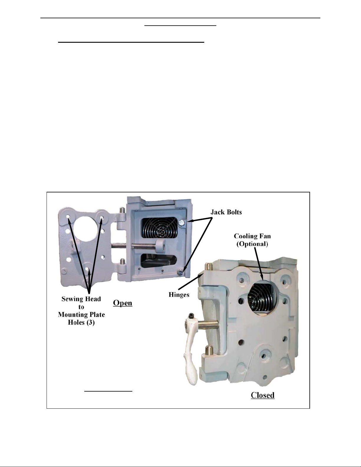
2.3 MOUNTING THE SEWING HEAD
Due to the size and weight of the sewing head, a dolly cart should be used to transport it. It
is best to have a couple of installers handling the sewing head. Be sure to hold it by the
main housing.
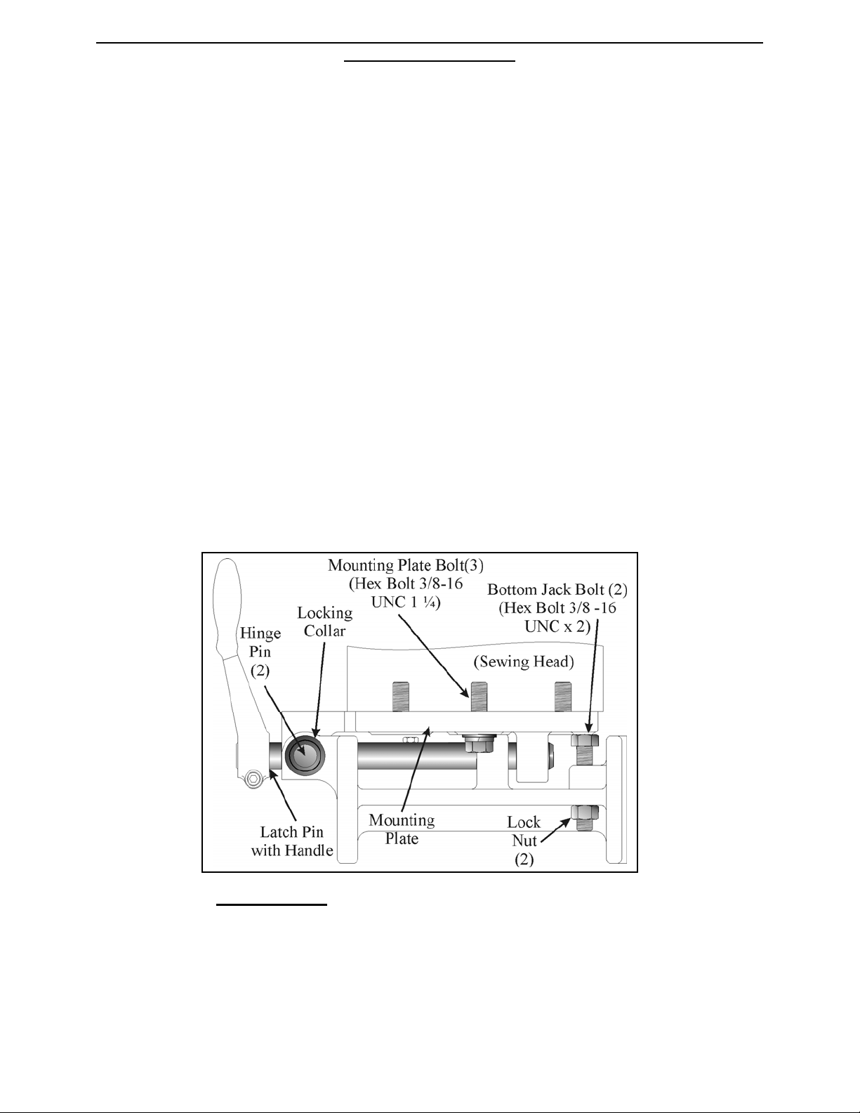
The sewing head is attached to the overarm assembly by a mounting plate, which mounts to
the back of the housing with three hex head bolts (Illustration 2.2). It is extremely important
that these bolts be securely tightened to the sewing head, because of the vibration common
to high performance systems.
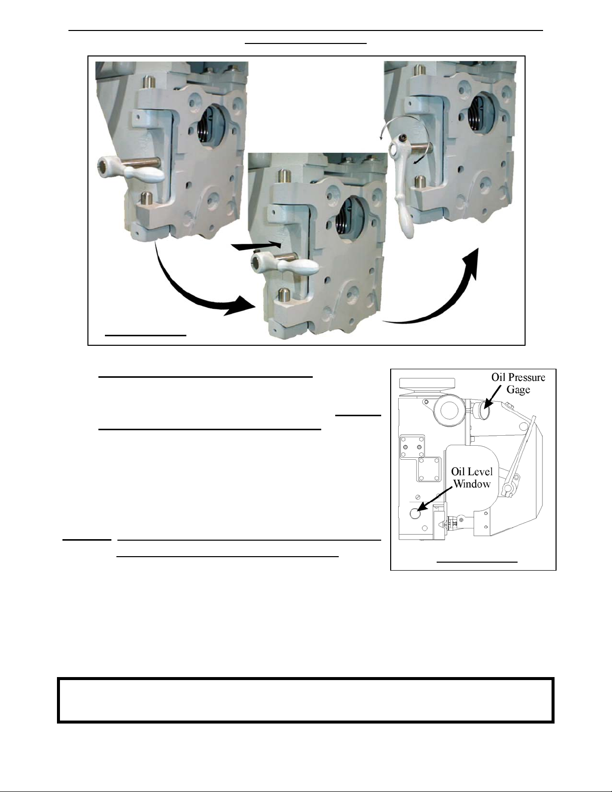
Refer to Illustrations 2.1 and 2.2. The mounting plate attaches to the overarm assembly
with two hinges. The hinges allow for easy access to various areas of the sewing head as
well as the cooling fan (optional). When the sewing head is rotated into the closed position,
the outer swinging edge of the mounting plate will come to rest on two jack bolts. The jack
bolts are used to provide the needed support during use and enable the latch pin to firmly
hold the plate. The mounting plate is locked into the closed position with a latch pin, which is
pushed in and rotated to secure the mounting plate. (Illustration 2.3) The locking rod
passes through a hole in the sewing frame and then through one in the mounting plate,
when in the closed position.
Illustration 2.1
(Shown with Cooling Fan Option)
FISCHBEIN
®
MODELS 200 & 201 EMPRESS
®
SEWING HEAD
(Short Stroke Technology)
OPERATOR’S MANUAL
REV. C 2013-6
10
If the jack bolts are not properly adjusted, the sewing head can vibrate possibly causing
damage or other parts to come loose. The jack bolts must be raised or lowered so that they
come into firm contact with the mounting plate. Both bolts come with a lock nut to keep them
in position.
The jack bolts are pre-set at the factory for the mounting plate that accompanies the sewing
system. The jack bolts will only have to be adjusted if they become loose or if replacing the
plate. To adjust the jacks, loosen the lock nuts and turn the jack bolts clockwise for about
five turns. Rotate the plate into the closed position until it comes into contact with the jacks
and then use the latch pin to secure the plate. The pin will probably rotate with ease and not
actually tighten when turned. Gradually keep trying the latch pin, while turning the lower jack
in increments, couterclockwise. The ideal setting for the lower jack is when the latch pin
tightens firmly before it has rotated the full 90
o
. (Illustration 2.3) Use the lower lock nut to
hold it in position.
Gradually turn the top jack couterclockwise until it comes into contact with the plate, when it
is in the closed position, but not locked with the pin. Unscrew the top jack one additional
rotation. Lock the top jack into position using the lock nut. When the plate is in the closed
position and secured into place, the latch pin will tighten completely before rotating the entire
90
o
and press firmly on the jack bolts.
Illustration 2.2 (Bottom View; sewing head in closed position)
FISCHBEIN
®
MODELS 200 & 201 EMPRESS
®
SEWING HEAD
(Short Stroke Technology)
OPERATOR’S MANUAL
REV. C 2013-6
11
2.4 LUBRICATION (WARNING)
Refer to Illustration 2.5. The sewing head is
delivered with a screw in the breather plug. Remove
this screw before starting up the head. Failure to
remove this will result in build up of internal pressure
and consequent damage to seals and other
components with possible injuries to the operator.
The sewing head is filled at the factory with oil (1 qts.
or 0.95 litres). SHC 626 Synthetic Oil
NOTE:
No substitution oils are accepted. Use of any
other oil will void the product warranty.
Pre-start up checks:
¾Check oil level (Oil window on the left side of the machine must be full with oil ).
(Illustration 2.4)
¾Check for indications of oil leaks. If any are found, perform the appropriate repair.
¾After a few seconds, the oil pressure gauge should indicate a
pressure between 15 PSI (1 bar) and 40 PSI (2,8 bar).
WARNING: Do not run the machine with oil pressure below
15 PSI (1 bar) or above 40 PSI (2,8 bar).
Illustration 2.4
Illustration 2.3
FISCHBEIN
®
MODELS 200 & 201 EMPRESS
®
SEWING HEAD
(Short Stroke Technology)
OPERATOR’S MANUAL
REV. C 2013-6
12
¾Replace the oil filter every 1000 working hours (see Section 2.5).
¾Replace the oil every 1000 working hours (see Section 2.5).
¾Approximately 1 qt or 0.95 litres will adequately fill the machine. SHC 626
Synthetic oil (ref. 31080) must be used.
¾Check the oil level when the machine is operating and the pressure is in the
specified range 15-40 PSI (1-2.8 bar). Note: The pressure must be checked after
the machine has fully warmed up (1.5 – 2 hours of operation).
¾In the event the oil level falls below the marker line, add oil until level is met.
2.5 MAINTENANCE:
NOTE: technical training is required to perform any maintenance on Fischbein sewing
heads.
DAILY
1. Keep the machine free of dust.
2. Clean with compressed air, using an OSHA approved air nozzle or with a
vacuum cleaner.
3. Check all seals for indications of oil leaks before start up.
4. Lubricate knife blades and presser foot hinges manually with standard
lubricating oil. Wipe all excess oil from parts.
5. Keep optical sensors clean according to their individual manual instructions.
6. Thoroughly, check for loose fasteners and tighten them back into position. If the
loose fastener holds a specific component in place that has a critical setting,
refer to the appropriate section of this manual to establish the correct setting.
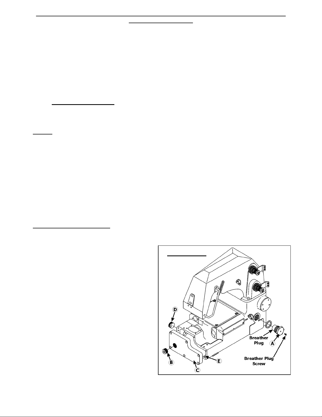
PERIODIC - OIL CHANGE
Oil changes are part of periodic maintenance performed after 1000 hours of operation.
(Illustration 2.5)
1. Lock out compressed air and
electrical power so the
machine cannot run.
2. Remove breather plug (A).
3. Unscrew the drain plug (B) in
the bottom cover (C).
4. Drain the used oil into a tray.
5. The drain plug (B) is
magnetic. Remove metal
particles and dirt sticking to it.
6. Wrap new Teflon® tape
around the drain plug (B).
7. Screw the plug (B) into the
bottom cover (C).
Teflon is the registered trademark of DuPont U.S.A.
Illustration 2.5

FISCHBEIN
®
MODELS 200 & 201 EMPRESS
®
SEWING HEAD
(Short Stroke Technology)
OPERATOR’S MANUAL
REV. C 2013-6
13
8. Fill the machine with one quart (0,95 litres) of oil through the breather plug hole
(A). A funnel and flexible tube are provided with the tool kit.
9. Re-install the breather plug (A).
10. Follow the recommendations for daily operation in Section 2.6.
PERIODIC - OIL FILTER REPLACEMENT
Oil filters are part of periodic maintenance performed after 1000 hours of operation.
(Illustration 2.5)
1. Lock out compressed air and electrical power so the machine cannot run.
2. Fill the replaced filter with oil.
3. Use a genuine Fischbein oil filter, ref. 15054.
4. Coat the seal on the new oil filter with a thin film of oil.
5. Remove the old oil filter.
6. Install the new filter (hand tightening is sufficient).
7. Run the sewing head in short, 2 to 3 second cycles until the filter is filled and the
pressure falls in the normal 15 to 40 PSI (1-2,8 bar) range.
2.6 START UP RECOMMENDATIONS
DAILY USE
:
Initially, start the machine in short, 2 to 3 seconds cycles until the
correct oil pressure is reached.
Running after prolonged shut down (two months and
over):
Replace the oil and filter and follow procedure in Section 2.5.
2.7 CONSUMABLES
The Fischbein Company recommends using Fischbein cleaning solvent (ref. 5-101), SHC
626 Synthetic oil (ref. 31080), Fischbein oil filter (ref. 15054) and Fischbein sewing thread.
Sewing heads Model 201 use crepe-sewing tape, available in a variety of basic colors and
widths. Seals, gaskets, knife blades, belts and any other part subject to normal wear
should be replaced with genuine Fischbein spare parts. If in doubt, contact your
Fischbein representative.
NOTE:
No substitute oils are accepted. Use of any other oil will void the product
warranty.
FISCHBEIN
®
MODELS 200 & 201 EMPRESS
®
SEWING HEAD
(Short Stroke Technology)
OPERATOR’S MANUAL
REV. C 2013-6
14
Illustration 3.0

FISCHBEIN
®
MODELS 200 & 201 EMPRESS
®
SEWING HEAD
(Short Stroke Technology)
OPERATOR’S MANUAL
REV. C 2013-6
15
3. MACHINE ADJUSTMENTS
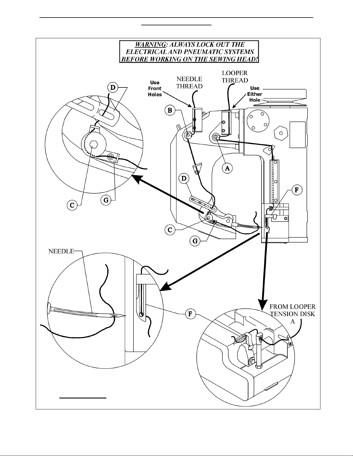
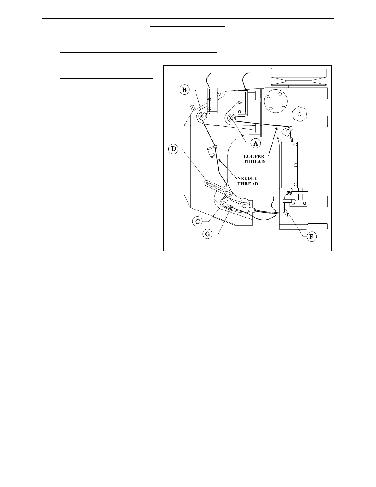
3.1 THREADING THE SEWING HEAD
3.1.1 LOOPER AND NEEDLE THREAD
1. Lock out compressed air and electrical power so the machine cannot run.
2. Refer to Illustration 3.0, page 14. Thread the needle as shown. A pair of needle nose
pliers may help in threading small areas.
3. The thread at the needle is laced through from machine’s infeed side towards the needle.
Let the thread stick out 4” (102mm) on the other side of the needle.
4. Ensure that the thread runs properly through the thread tensioning discs B & C.
5. Thread the looper (F) as shown.
6. The thread at the looper (F) must first go through the top hole and then through the
bottom hole. About 4” (102mm) should be left sticking out of the looper. (Illustration 2.6).
7. To complete a chain off, a piece of bag material should be placed between the presser
foot and the throat plate before running the machine. Loosen the sewing head drive belt
tension. Turn the pulley by hand in a clockwise direction so the sewn bag proceeds
forward through at least three complete cycles. This will start the chaining process. Run
the system to clear out the test bag material, before attempting to run a bag through the
system. If this procedure is not followed, it will not start a chain and the machine
might break the needle.
8. A Model 201 tape sewing head must have tape between the presser foot and feed dog to
operate. The 201TCS can sew a chain with or without crepe tape. Check the looper to
ensure no thread has accumulated around it.
FISCHBEIN
®
MODELS 200 & 201 EMPRESS
®
SEWING HEAD
(Short Stroke Technology)
OPERATOR’S MANUAL
REV. C 2013-6
16
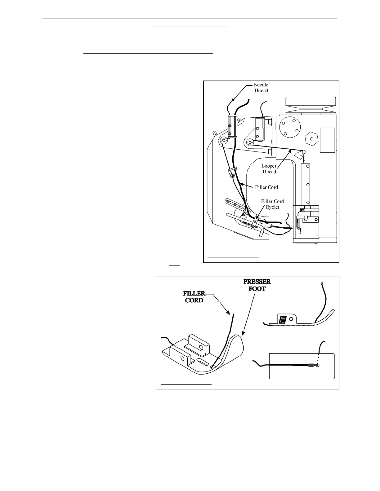
3.1.2 FILLER CORD (OPTIONAL)
1. Turn OFF and lock out electrical and pneumatic systems before attempting to thread the
filler cord.
2. Follow Illustrations 3.1 and 3.2 to thread
the filler cord with the looper and needle
thread. Note that the filler cord does NOT
get threaded through the thread pull off.
3. Once the thread has been threaded through
the Filler Cord Eyelet (Illustration 3.1), it
will be threaded through the presser foot as
shown in Illustration 3.2.
4. The bottom of the presser foot is designed
with a channel, which runs from the filler
cord hole to the back of the presser foot.
5. To complete a chain off, a piece of bag
material is placed between the presser foot
and the throat plate before running the
machine. Turn the pulley by hand in a
clockwise direction so the sewn bag
proceeds forward through at least three
complete cycles. Run the system to clear
out the test bag material, before attempting
to run a bag through the system. If this
procedure is not followed, it will not start
a chain and the machine might break the needle.
6. The needle thread sews
through the filler cord. Be
sure to leave about 4 inches
(102 mm) of filler cord
(chaining) out past the back
of the presser foot before
running the first bag through
the system.
7. It is very important to keep
the needle thread and the
filler cord separated and not
to let them accidentally twist
together while threading or
running the sewing system.
Illustration 3.1
Illustration 3.2
FISCHBEIN
®
MODELS 200 & 201 EMPRESS
®
SEWING HEAD
(Short Stroke Technology)
OPERATOR’S MANUAL
REV. C 2013-6
17
3.2 THREAD TENSION ADJUSTMENT
1. Looper thread tension (A):
The tension on the looper
thread must be light and even
as the thread is pulled with a
steady, even motion. If the
tension is not even, or a large
force is required to pull the
thread, the source of the
problem must be found and
corrected before running the
machine.
2. Needle thread tension (B):
Illustration 3.3. The needle thread tension is adjusted with the thread tensioner (B).
The needle thread tension should put a noticeable drag on the thread. Tension also
varies with stitch length and thickness of material to be sewn.
This adjustment can be combined with thread pull off positioning (D). On the needle
arm, thread tensioner (C) prevents thread pulled by the thread pull off from sagging too
close to the needle. Tension is very slight and the adjustment is fixed. Factory settings
of tension are made for a 4-ply paper bag with a stitch length of 2.5 stitches per inch
(10 mm per stitch) using Fischbein synthetic thread 12/5, unless otherwise specified
when ordered, which is valid in most cases.
Illustration 3.3
FISCHBEIN
®
MODELS 200 & 201 EMPRESS
®
SEWING HEAD
(Short Stroke Technology)
OPERATOR’S MANUAL
REV. C 2013-6
18
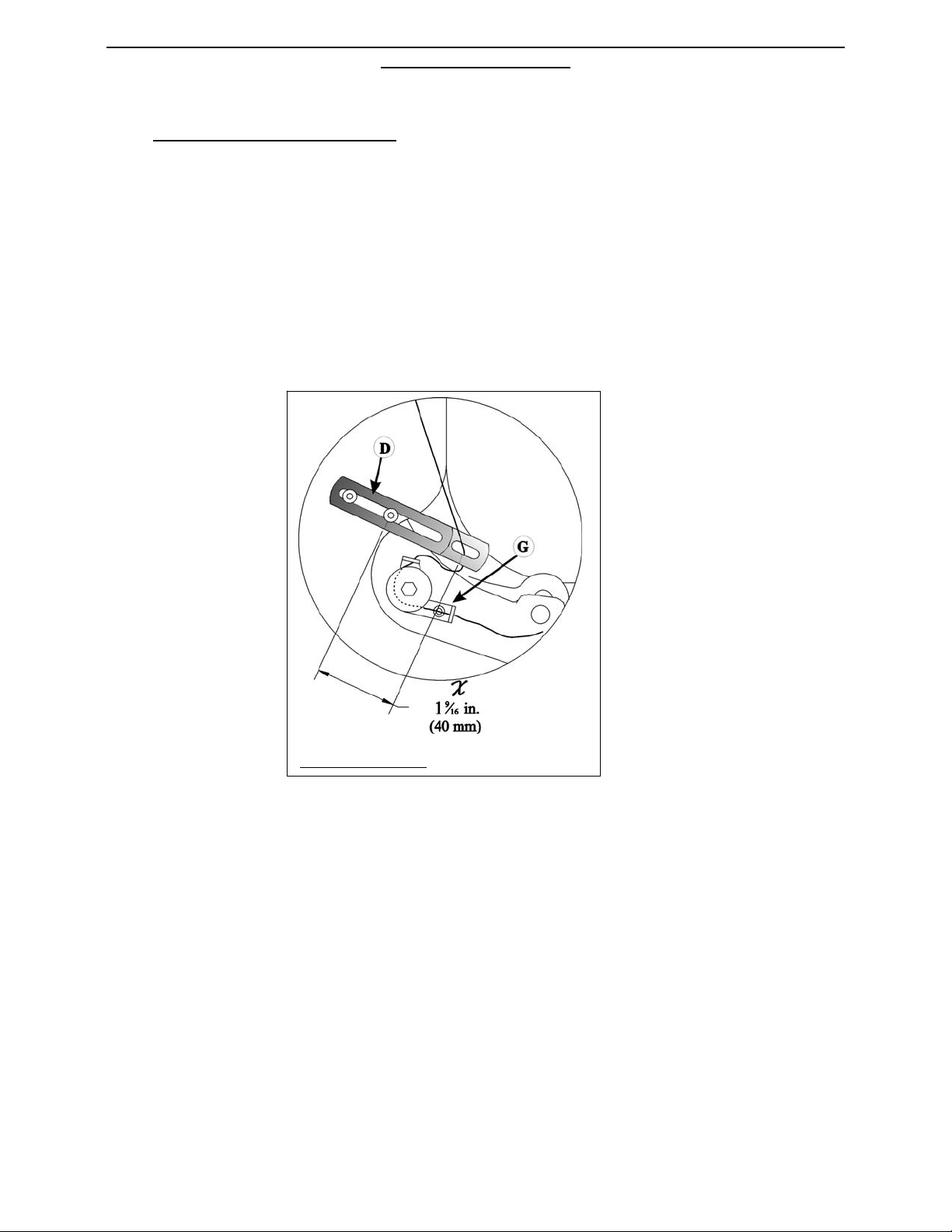
3. Thread pull off adjustment
Illustration 3.4 shows the factory setting. This is suitable in many cases.
For thin materials, distance Xmust be shorter.
For thick materials, distance Xmust be larger.
If the stitch is too loose, try first to adjust with the needle thread tension before
shortening the distance Xof the thread pull off.
Illustration 3.4
FISCHBEIN
®
MODELS 200 & 201 EMPRESS
®
SEWING HEAD
(Short Stroke Technology)
OPERATOR’S MANUAL
REV. C 2013-6
19
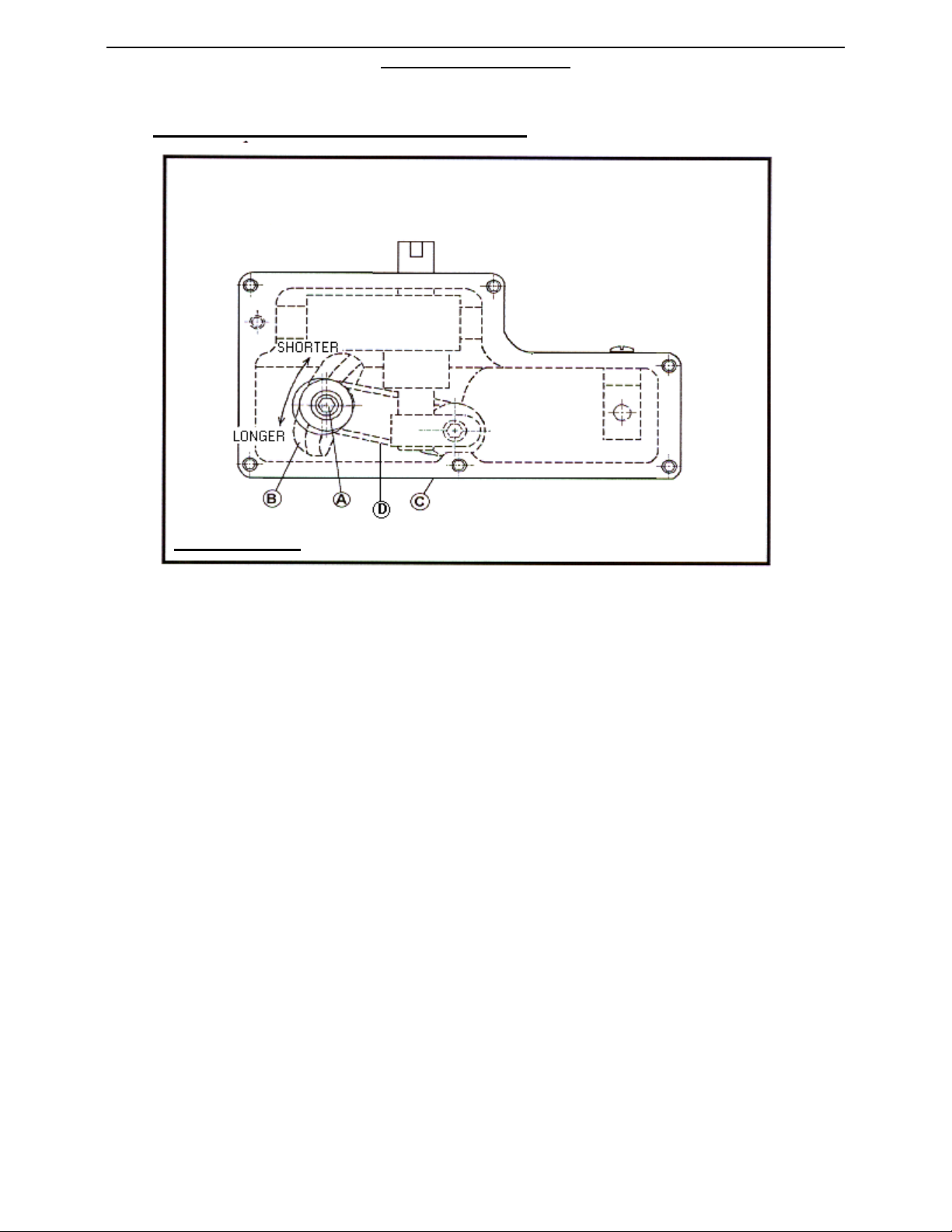
3.3 STITCH LENGTH ADJUSTMENT
The standard factory setting of the stitch length is 2.5 stitches per inch (.40” per stitch,
10 mm per stitch). Other stitch lengths can be set according to customer requirements.
If a change is needed, please follow the procedure below:
1. Be sure the feed dog is down below the surface of the throat plate, by rotating the drive
pulley clockwise. (Illustration 3.6)
2. Stand the sewing head on its drive pulley so that no oil can flow out when removing the
bottom cover (C, Illustration 2.5 and 3.5). Block the head to prevent it from rotating on
its pulley.
3. Remove the oil drain plug (Illustration 3.5) from the bottom cover (C). The drain hole
will provide access to the socket cap screw (A), used in adjusting the stitch length.
4. With a 3/16” allen wrench, loosen (but do not remove) the socket cap screw (A)
(#SC142878). (Illustration 3.5) The screw may fall into the housing if it is removed.
5. The stitch length is changed by moving link (D) (Illustration 3.5) along the slot in link (B).
Moving link (D) toward the throat plate shortens the stitch. Moving it away from
the throat plate lengthens it.
6. Tighten the socket cap screw (A), but not fully yet.
Illustration 3.5:
(Bottom View)
Other manuals for Empress Series
1
This manual suits for next models
2
Table of contents
Other FISCHBEIN Industrial Equipment manuals


