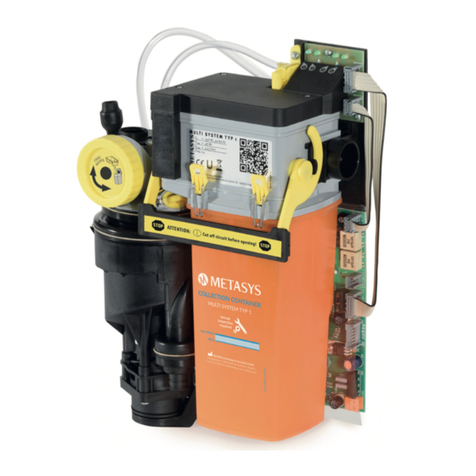
Metasys MST 1 ECO Installation instructions

Separierautomatik
MULTI SYSTEM TYP 1 ECO
Gerätedokument
Einbau, Betrieb und Wartung
Automatic separator
MULTI SYSTEM TYP 1 ECO
Equipment Logbook
Assembly, operation and maintenance
Séparateur automatique
MULTI SYSTEM TYP 1 ECO
Livret d’appareil
Installation, fonctionnement et entretien
Separatore automatico
MULTI SYSTEM TYP 1 ECO
Verbale d’installazione
Montaggio, funzionamento e manutenzione
MST 1
ECO
EN

EN
2
1. Index
The header on each page defines the user group particular information is
aimed at.
Chapter Page
1. Index 2
2. Explanation of the pictograms 2
3. General information 3
4. Application 4
5. Construction 4
6. Explanation of the type plate 4
7. Technical data 5
8. Functional description 5
9. Installation options 6
10. Guidelines for installation 6
11. Connections 7
12. Description of the internal display 8
13. Full system conversion 8
14. Replacement of the collection container 9
15. Disposal of the full container 10
16. Maintenance, cleaning and disinfection 11
2. Explanation of the pictograms
iInformation
Caution!
General warning sign
Follow instructions for use
Index Explanation of the pictograms
Practice personnel, technicians

3
EN
3. General information
The safety, reliability and performance of the appliance is
only guaranteed by METASYS if the following instructions are
observed:
Assembly, alterations or repairs may exclusively be carried out
by authorized service personnel in compliance with EN Standard
60601-1 (International Standard for Medical Electrical Apparatus, in
particular Part 1: General Rules for Safety).
The electrical installation must comply with the regulations of the IEC
(International Commission for Electrical Engineering).
The apparatus must exclusively be used in conformity with the
instructions for installation, operation and maintenance.
Only original parts may be used for repairs or replacements.
All the guidelines provided by the manufacturer on the correct use of
the MULTI SYSTEM 1 ECO are followed.
After commissioning, complete the proof of installation at the front
page of this manual and send this to METASYS in order to dene the
warranty period.
All inspection and service work must be entered into the device docu-
mentation at the rst pages of this manual
When requested by an authorized engineer, METASYS agrees to make
all documents available for the use of technically qualied service
personnel.
METASYS acceptsnoresponsibilityfordamagescaused due to external
factors, such as wrong installation, improper use of the apparatus or
unauthorized technical intervention.
Users must study equipment and assure themselves of its good
condition before every use.
Certificates of recycling for the amalgam waste (provided by recycling
company) must be kept in accordance with national regulations.
When the complete amalgam separator is dismantled at the end of
its service life, it must be returned to the manufacturer for orderly
disposal.
General information
Practice personnel, technicians

1 2
CD-01234
0000
3.4
3.2
3.1
3.5
3.6
3.3
3
EN
4
Application Construction Explanation of the type plate
Practice personnel, technicians
4. Application
MULTI SYSTEM TYP 1 ECO (abbreviated: MST 1 ECO) is a single unit, auto-
matic air/water separator with integrated heavy parts collector and place
selection valve.
5. Construction
The automatic separator MST 1 ECO consists of 2 modules:
1 Module 1 Module 1 is the central component containing all the
air, water and electrical connections.
Module 1 contains the wall mounting bracket, the cir-
cuit board and the diagnostic board.
2 Module 2 Module 2 is the separating unit where the
sedimentation takes place.
Module 2 contains the collection container, separator
and place selection valve.
6. Explanation of the type plate
3 See illustration
The type plate can be found on module 1 and is visible when module 2
is removed (lift the yellow locking handles upwards and pull module 2
forwards out of the housing.
3.1 Equipment type
3.2 Mains supply data
3.3 Serial number
3.4 Address of the manufacturer
3.5 CE conformity mark
3.6 Separate collection electrical / electronic equipment

4
5
163 mm
305 mm
104 mm
5.1
5.2
5.3
5.5
5.4
5.7
5.6
5.8
5
EN
Technical data Functional description
Practice personnel, technicians
7. Technical data
Power supply 24 V AC
Frequency 50/60 Hz
Max. current consumption 1,5 A
Max. power input 15 VA
Low pressure range 50 mbar - 250 mbar
Collection container volume 300 cm3
Max. ambient temperature 40 °C
Possible suction systems wet or dry vacuum systems
Max. water ow rate 0,5 l/min at suction side
4see illustration,
total dimensions (H x W x D) 305 x 163 x 104 mm
8. Functional description
5 See illustration
By lifting the suction hose, the place selection valve is
opened 5.1 and the suction stream 5.2 is fed into module 2. Once
there, using the „cyclone principle“, the air and water are separated 5.3 .
The dry air leaves the system through the place selection valve to the
suction motor 5.4 .
The remaining uid and residues are forced into the collection container
5.5 where the sedimentation takes place.
As the coarse particles in the collection chamber sediments the uid level
rises. As soon as the uid level reaches the limit probes 5.6 , the pump
motor 5.7 is started for a set period of time. The pump forces the pre-
cleaned uid into the water outlet 5.8 .
Waste water from the spittoon is directly led into the water outlet.
A maximum probe (emergency stop) prevents the ooding of the
separation chamber by closing the place selection valve. This prevents
liquid from entering the suction machine.

6
7
8
9
9.1
EN
6
Installation options Guidelines for installation
Practice personnel, technicians
9. Installation options
The MST 1 ECO allows a variety of different installation options:
iOptions 6and 7 must full the norm EN 60601.
6 Installation in the spittoon bowl
The direct installation of the automatic separator into the spittoon bowl
should be preferred in order to keep tubes to the automatic separator as
short as possible.
The automatic separator should be installed in the spittoon in such a way
as to keep the vibration levels as low as possible.
7 Installation behind the patient’s head (12 o’clock)
If there is no spittoon in the treatment area and the suction system is
located behind the head of the patient, then the MST 1 ECO can be
installed inside a cabinet.
In this case the connection to the spittoon must be closed with a sealing
plug.
8 Installation within an independent housing
Should it be impossible to integrate the automatic separator into the
existing equipment, it can be tted in a shapely housing which requires
only a minimum amount of oor space.
The housing should be be mounted onto the connection box of the dental
unit. An external display and a transformer are already integrated into
the housing.
10. Guidelines for installation
9 Fitting
iThe following space requirement must be met:
H x W x D = 350 mm x 205 mm x 120 mm
To reduce vibration, the device must only be tted to the supporting parts
of the treatment unit through the 3 holes in module 1 (do not remove the
swinging ttings!).
An electrical earth plate ( 9.1 ) must be tted behind
module 1 if the background is electrically conducting!

10
10.1
11
12
13
11.1
12.2
12.1
12.4
12.3
12.4
13.1
13.3
13.2
13.4
12.3
7
EN
Guidelines for installation
Technicians
10. Guidelines for installation
10 Pre lter
If not already installed in the tube holder, a pre lter 5.1
with a mesh width of max. 1 mm must be installed on the
suction side of the separator!
11 Hose connections
iThe hose connections leading to the MST 1 ECO must be kept as
short as possible to prevent pre-sedimentation.
Dirty dental hoses must be replaced during installation and must be
disposed of through DENTAL ECO SERVICE. The automatic separator must
be connected via an odour seal 6.1 to the waste water pipe. Water driven
saliva ejectors should not be used due to excessive water consumption.
Main switch: The connection of the 24 V AC power supply
must take place after the device’s or the surgery’s main
switch.
11. Connections
12 Hose connections (see illustrationd)
12.1 Connection to spittoon waste water pipe
12.2 Connection to suction hose (to the suction holder)
12.3 Connection for vacuum hose (to suction engine)
12.4 Anschluss für Ab ussschlauch (Reinwasserauslauf)
Order numbers of hose nozzles and adapters can be found in our spare parts
list.
All hose connections must be secured using hose clips!
Unnecessary connections must be closed with blind plugs!
13 Electrical connections (see illustration)
13.1 MST 1 ECO main board
13.2 MST 1 ECO diagnostic board
13.3 Module 2
13.4 Holder switch and suction machine separation relay
SV3 Plug for electricity supply 24 V AC
The supply voltage must be taken from a safety transformer
which complies with the requirements as per IEC 601-1 / VDE
0750 Part 1 / DIN EN 60601-1 and IEC 60742 + A1 / DIN EN
60742.
SV5 Verbindung zur Diagnoseplatine (Stromversorgung für Motor
und Magnetventil im Modul 2)
SV6 Verbindung zur Diagnoseplatine (Sonden im Modul 2)
SV7 Stecker für Ablagesignal (12-24 V AC oder DC)
F1 Hauptsicherung T3.15 A (darf nur durch selben Typ ersetzt
werden!)

14
15
16
17
14.1
14.2 14.3
EN
8
12. Description of the internal display
14 The internal display is located on the diagnostic board above the
main board and provides information about the current operating
status of the automatic separator.
14.1 LED 1: Hose rest signal
Suction hose is lifted
(12-24 V AC or DC to plug SV7)
14.2 LED 2: Solenoid valve
The solenoid valve in module 2 is triggered (emergency stop
probe is not triggered).
14.3 LED 3: Pump module 2
The pump in module 2 is triggered.
13. Full system conversion
iUsing the conversion kit (order no. 40050009) it it possible
to upgrade the automatic separator MST 1 ECO to the full-
featured amalgam separator MST 1 (see illustration):
Unlock and pull out module 2
Remove ECO main board
Remove spittoon drain hose and water outlet hose; completely
remove the connection hose from the elbow and the water outlet
Attach MST 1 clean water outlet
Attach MST 1 main board and make connections
Glue hose sleeve on the lter housing for spittoon outlet
Attach lter housing with Z-inlet seal, place on spittoon outlet hose
and secure; fasten probe cables in the guides and connect to the
main board at plug SV1
Push centrifuge bearing on the guide pins and secure with enclosed
safety washer
Return pump hose ø 4 x 6 mm, l = 440 mm and place it on the
connection of the centrifuge pump
Attach centrifuge, attach the cover of the centrifuge inlet seal, push
centrifuge base up, secure with clip and plug in centrifuge plug at
connection SV2
Attach connection hoses on elbow ttings and at the inlet body
Fit external display visibly at the treatment site and connect to the
main board
Check module 2 (pump sieve, probes, solenoid valve, etc.), adjust if
necessary.
Grease o-rings for corner piece of module 2 and o-rings side
insertion and insert module 2
See illustrations 16 and 17 : When proper operating conditions
are conrmed, attach the type plates on the xture (module 1) and
on module 2
Description of the internal display Full system conversion
Technicians

18 19
20
21
22
23
24
25
22.2
22.1
22.3
9
EN
15. Replacement of the collection container
Switch off the main switch of the unit! Wear protective
gloves!
Prepare a new collection container and take out the enclosed disin-
fectant bag!
Remove the lid of the treatment unit.
18 Turn the locking bracket upwards.
19 Remove Module 2 by pulling it forwards out of the unit and
place it on a level, non-slip surface..
20 Open the four yellow clips on Module 2.
21 Holding the collection container firmly, pull off the top.
22 If the pump filter 22.1 is soiled, remove it, clean it and place
back onto the pump housing. The probes 22.2 in Module 2 can
be cleaned with a soft cloth. The air deflector 22.3 can also be
removed for careful cleaning.
When assembling again pay attention to the position mark-
ing (arrow on the air brake, notch on module 2)!
23 Put the cleaned and properly re-assembled module 2 on to
the new collecting tank.
Paying attention to the FRONT marking on the container!
24 Close the four yellow clip closures on Module 2.
iClean the sealing rings on the left and right in the fixture
with a damp napkin and grease with vaseline.
25 Push the module carefully back into the fixture and close the
locking handle.
Switch on the main switch!
Replacement of the collection container
Practice personnel, technicians

26
28
30
27
29
31
33
FRANCE NORWAY SLOWENIA
GERMANY PORTUGAL SWITZERLAND
AUSTRIA
LATIVA SLOVAKIA UNITED KINGDOM
FINLAND
Sammelstellen | Collection Centers
Gritter Dental Pty Limited
29 / 55-59 Norman Street
Mortdale NSW 2223
Australia
DENTAL ECO SERVICE GmbH
Florianistr. 3
6063 Rum bei Innsbruck
Österreich
Remeo Oy
Linjatie 6
01260 Vantaa
Finland
METASYSFrance s.a.r.l.
9 bd, Edmont Michelet
69008 Lyon
France
DENTAL ECO SERVICE GmbH
Am Ländbach 16
82481 Mittenwald
Deutschland
Freiberg Thomas SIA
Dirnavu iela 135 – 413
1050 Riga
Lativa
Dental Sor
Saltverket 6
4515 Mandal
Norway
Ambimed&Buffer
Poligono Quimiparque
Rua 34
2830 Barreiro
Portugal
SAFINA SLOVAKIA s.r.o.
Turčianska 52
82109 Bratislava
Slovakia
EKOL d.o.o.
Laze 18a
4000 Kranj
Slowenia
DHL Logistics (Schweiz) AG
Heldaustrasse 66
9470 Buchs
Schweiz
Blueprint Dental
15b Oakcroft Road
KT6 1RH Chessington, Surrey
United Kingdom
Unsere Entsorgungsdienstleistung
DENTAL ECO SERVICE - METASYSbietet ein umfassendes Sammel- und Entsorgungskonzept
für sämtliche dentale Abfälle (z.B. Röntgenchemikalien / Bleifolien). Im Gegensatz zu
allgemeinen Entsorgungsunternehmen, übernimmt DENTAL ECO SERVICE alle Arten von
Dentalabfällen und bietet Zahnärzten somit eine unkomplizierte Möglichkeit, Abfallstoffe
zu entsorgen. Informieren Sie sich unter www.metasys.com „Entsorgung &Recycling.“
DENTAL ECO SERVICE - METASYSoffers a comprehensive dental waste management
concept. This services meets the specic needs of dental practices. Unlike general industrial
waste management companies, DENTAL ECO SERVICE handles all types of dental waste and
therefore provides an uncomplicated way for dental practices to dispose of waste material.
Please check www.metasys.com „Dispose &Recycle“ for more information.
Our Disposal Service
Depot: .................................. E-Mail: ........................................
Techniker: ............................. Telefonnummer: ...........................
Für Techniker und Depot | For technicians and dealer
ECO TRANSFORM
Ersatzbehälter für METASYS
Amalgamabscheider und ECO CENTER
Exchange container for METASYS
amalgam separators and ECO CENTER
COMPACT Dynamic
M1-L0.130/01
Gesamtentsorgung
Besuchen Sie www.metasys.com „Entsorgung &Recycling“ für weitere Informationen.
Please visit www.metasys.com „Dispose &Recycle“ for more information.
Dental Waste Disposal
Dealer: ................................. E-mail: ........................................
Technician: ........................... Phone: .........................................
Bitte vor Rücksendung ausfüllen! | Please complete before return.
MULTI SYSTEM TYP 1
www.metasys.com
www.metasys.com
Für die Entsorgung Ihres gefüllten
Behälters wenden Sie sich bitte an die
lokale DENTAL ECO SERVICE / METASYS
Sammelstelleoder kontaktierenSie uns:
INT: +43/512/20 54 20-0
DE: +49/2236/37 42 42
Forrecycling of thefull container please
contactyour local DENTALECO SERVICE /
METASYScollection point or contact us:
INT: +43/512/20 54 20-0
www.metasys.com
Für unsere Entsorgungskunden
aus Österreich / Schweiz /
Deutschland
Verwenden Sie für die Rücksendung
Ihres gefüllten Behälters das
beiliegende Rücksendeetikett!
Bitte geben Sie bei der Einzahlung
Ihrer Rechnung immer Ihre
Rechnungsnummer an.
Empfänger / Consignee
ECO TRANSFORM
AUSTRALIA
Absender / Sender
32
EN
10
15. Disposal of the full container
Wear protective gloves and face mask!
Avoid contact with the contents of the container!
The collection container is designed for single use. The reuse of a used
container violates the warranty regulations!
The full amalgam separator can be disposed of at the in-house
recycling company DENTAL ECO SERVICE - METASYS Group. Certi cates of
recycling need to be stored according to national law.
When the whole amalgam separator is disassembled at the end of its
operational life, it must be returned to the manufacturer for orderly
disposal.
The simplest method of disposal:
ECO TRANSFORM
!
26 Cut one end of the disinfectant bag enclosed with the new
container and empty it into the full container for nal
disinfection.
27 -
29
Close the full container rmly using the green lid which is
also provided with the new container, by twisting it clockwise.
Check if the lid is fully closed by holding the closed container
upside down over a drip tray (if required, re-tighten the lid).
30 -
31
Place the tightly closed collection container into the two half
polystyrene shells of the transport carton. Close the transport
carton according to the enclosed handling instructions.
32 Place the appropriate return label onto the transport box
for recycling at DENTAL ECO SERVICE ( more information on
recycling options in your country on: www. metasys.com)
33 Any amalgam residues from the pre lter must be collected
in a suitable container (e.g. METASYS ECO CENTER) and dis-
posed of properly with ECO TRANSFORM.
Operating the amalgam separator without a pre lter is not
allowed! Do not suck in residues from the pre lter!
Please go to
www.metasys.com/collection_centers
to locate your national collection point.
Disposal of the full container
Practice personnel, technicians
return label
Visit
www.metasys.com/collection_centers
to receive more information
about ECO TRANSFORM

34
35
36
37
38
11
EN
Maintenance, cleaning and disinfection
Practice personnel, technicians
16. Maintenance, cleaning and disinfection
34 See illustration
Shortly operate the spittoon bowl after every treatment!
35 See illustration
Suck off some water with each of the suction tubes after every treatment.
36 See illustration:
Twice a day, after having sucked off some water, use GREEN&CLEAN M2,
the disinfectant prescribed by METASYS, for cleaning and disinfection.
GREEN&CLEAN M2 should be used before longer periods of downtimes
of the dental unit (e.g. lunch break, end of the working day or holidays).
37 See illustration
The spittoon bowl should also be rinsed with GREEN&CLEAN M2 twice a
day.
The operation of the amalgam separator COMPACT Dynamic without
prelter at the dental unit and/or at the central suction system is not
permitted!
Cleaning the prelter:
The prelter must be emptied and cleaned at least once a week. This may
also be carried out daily, depending on workload.
38 See illustration
The amalgam residue from the prelter box must be collected in the
METASYS ECO CENTER and disposed of properly with ECO TRANSFORM.
www.youtube.com/user/METASYSMedizintech

METASYS ... makes the difference!
2018-03 ZK-55.060/02 70100022 Druck- und Satzfehler vorbehalten! / Subject to printing and setting errors!
Visit us at:
METASYS Medizintechnik GmbH
Florianistraße 3, 6063 Rum bei Innsbruck, Austria
1 +43 512 205420 | 5 +43 512 205420 7
GERMANY
+49 8823 938 44 33
FRANCE
+33 4 37 90 22 15
ITALY
+39 045 981 4477
Table of contents
Other Metasys Water Filtration System manuals
Popular Water Filtration System manuals by other brands

KineticoPRO
KineticoPRO NSC-120 owner's manual
Premier
Premier WP-2 LCV Installation, operation and maintenance manual

AquaCo
AquaCo SYS-925 manual

MSR
MSR GUARDIAN GRAVITY instruction manual
OMEGA AIR
OMEGA AIR AK AAF Series Installation and operating manual
JABSCO
JABSCO 59000-1000 Aqua Filtr Instruction booklet
Bestway
Bestway Hmax 58498E owner's manual
Arkal
Arkal Spin Klin Angle Apollo 3" Service maintenance manual

amiad
amiad TEQUATIC PLUS F-150 Installation, operation and maintenance manual
Honeywell
Honeywell MiniPlus FF06 installation instructions
Grunbeck
Grunbeck FS-B Operation manuals
Finerfilters
Finerfilters DFT8 Instruction and maintenance manual
