Finerfilters DFT8 Instructions for use
DFT8 Reverse Osmosis Filter
Instruction and Maintenance Manual
Finerfilters Limited
Unit 21, A K Business Park Russell Road Southport Merseyside PR9 7SA
[email protected] / 01704 807600

Page 1
DFT8 Reverse Osmosis Filter
Contents
1) General Information
2) System Layout and Components
3) Preparation and Installation
4) User Guide
5) Maintenance
6) Filter Replacements
7) Precautions and Parameters
Page 2
DFT8 Reverse Osmosis Filter
General Information
Installation Guidelines
This Reverse Osmosis (RO) system is engineered for easy
installation by someone with basic DIY and plumbing skills. It
should be connected to the home's primary water supply.
Water Pressure and Temperature:
Ensure your water supply maintains a pressure between 1 to 4
bars, with a temperature range of 5ºC to 45ºC.
If the pressure falls below 1 bar or rises above 4 bars, install a
booster pump or pressure-reducing valve between the main
water supply and the RO unit.
Installation Location:
Do not install the RO unit outdoors if the temperature exceeds
the specified range or if the area receives direct sunlight.
A suitable installation spot is a cupboard beneath a sink, often
close to the main water inlet valve. If the water supply is not
nearby, additional plumbing will be necessary.
Chemical Storage:
Avoid storing harsh chemicals like strong acids or alkalis near the RO unit to prevent potential
damage.
Filter Accessibility:
Position the RO unit to allow horizontal removal of the filters. If space is limited, you may need to
tilt the unit or slide it forward for easier access.
Flow Rate:
It's normal for the flow rate of filtered water to decrease with lower water pressure or
temperature.
Important Notes:
This unit is designed for domestic mains water supply only. If the water supply contains higher
levels of raw water, install a pre-filter between the shut-off valve and the unit to prolong the RO
system’s lifespan.
Do not obstruct the drainpipe or install any valves, as this will hinder efficient wastewater
drainage.
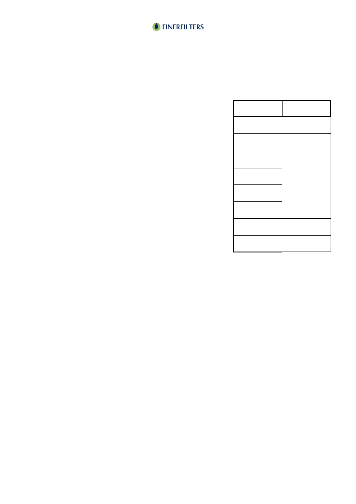
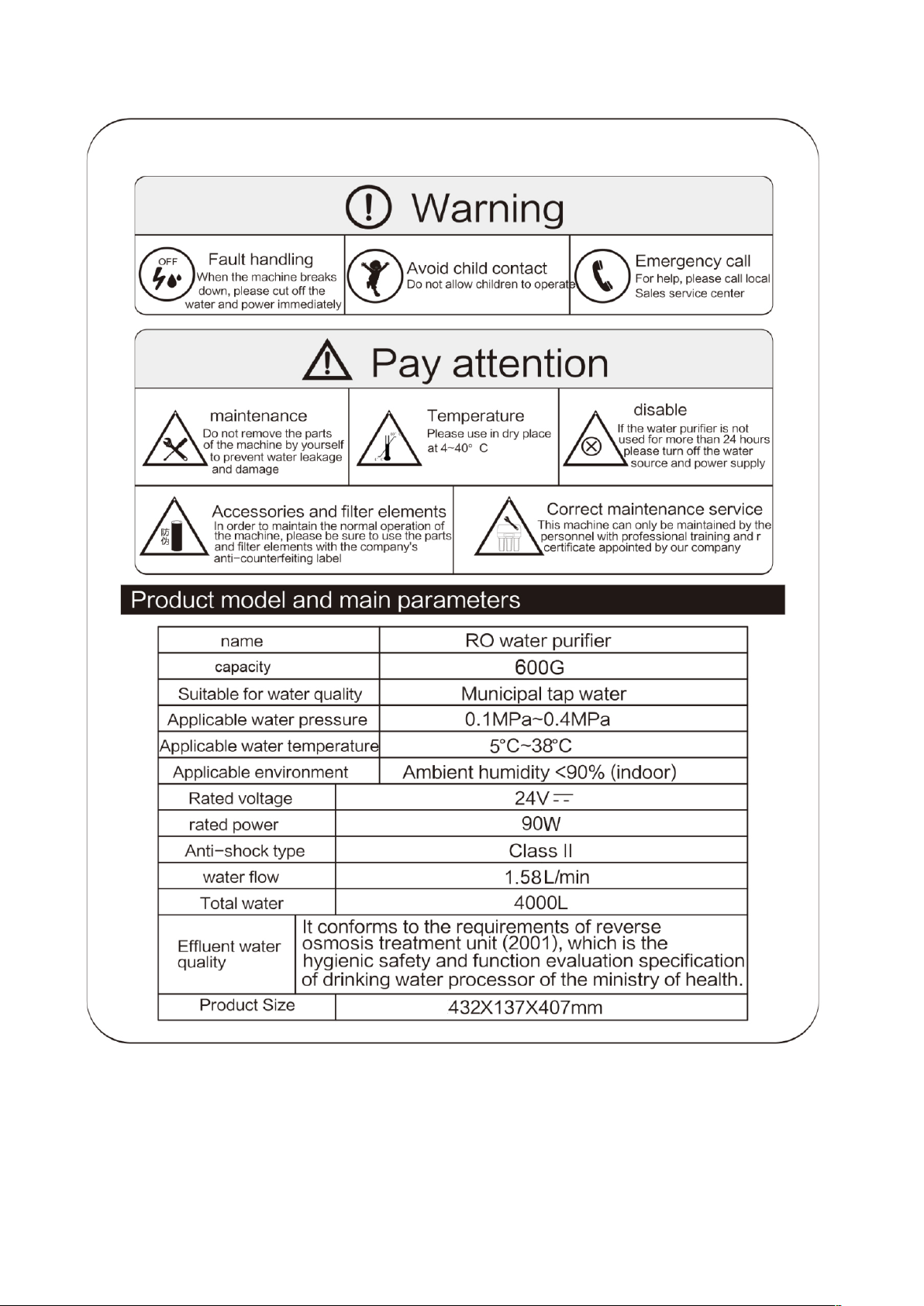
Model
DFT8 - 600
System
Reverse
Osmosis
Filtration
Accuracy
0.0001
Micron
Daily water
Flow
600gal
Water temp
5ºC - 45ºC
Water source
Municipal
water
Inlet water
pressure
1Bar min
4Bar max
Dimensions
mm
381x165x435
Weight
7.8kg
Page 3
DFT8 Reverse Osmosis Filter
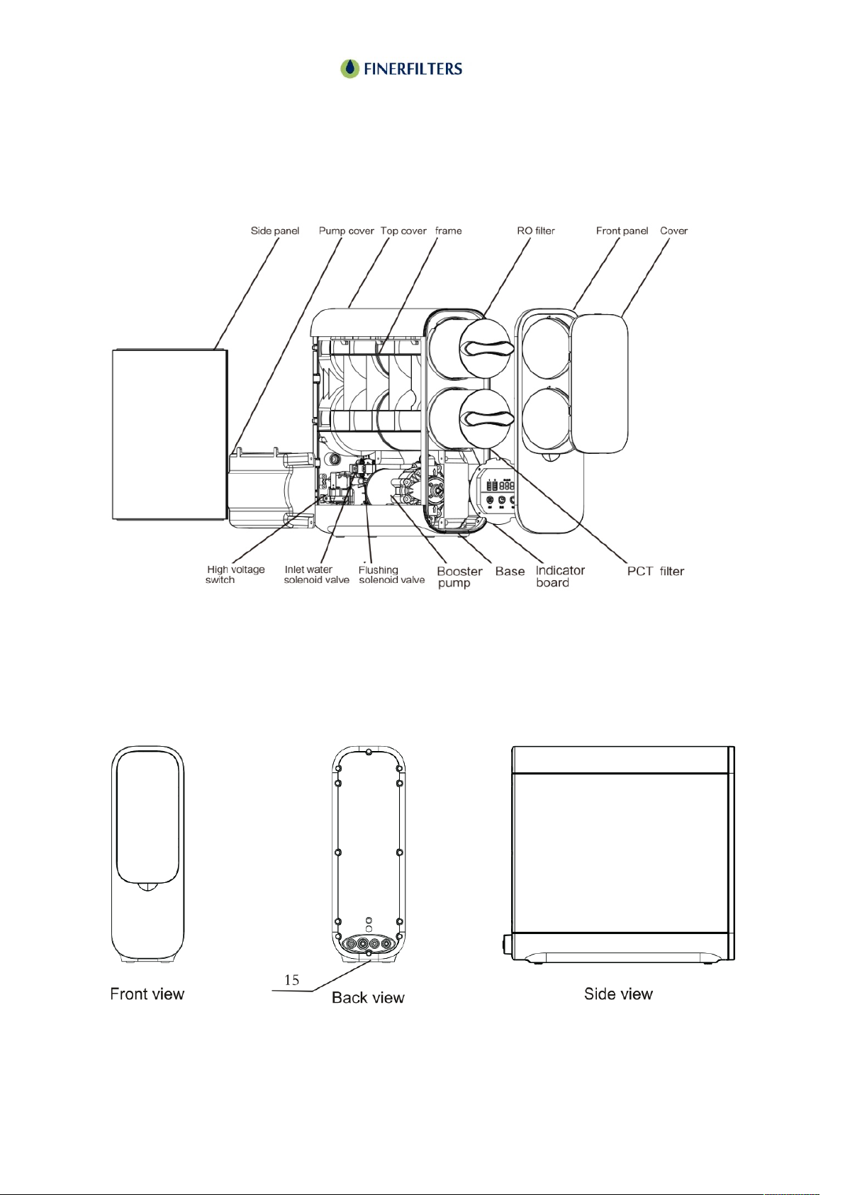
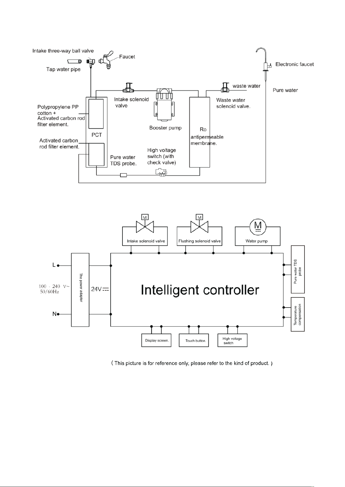
System Layout and Components
Page 4
DFT8 Reverse Osmosis Filter
Preparation and Installation
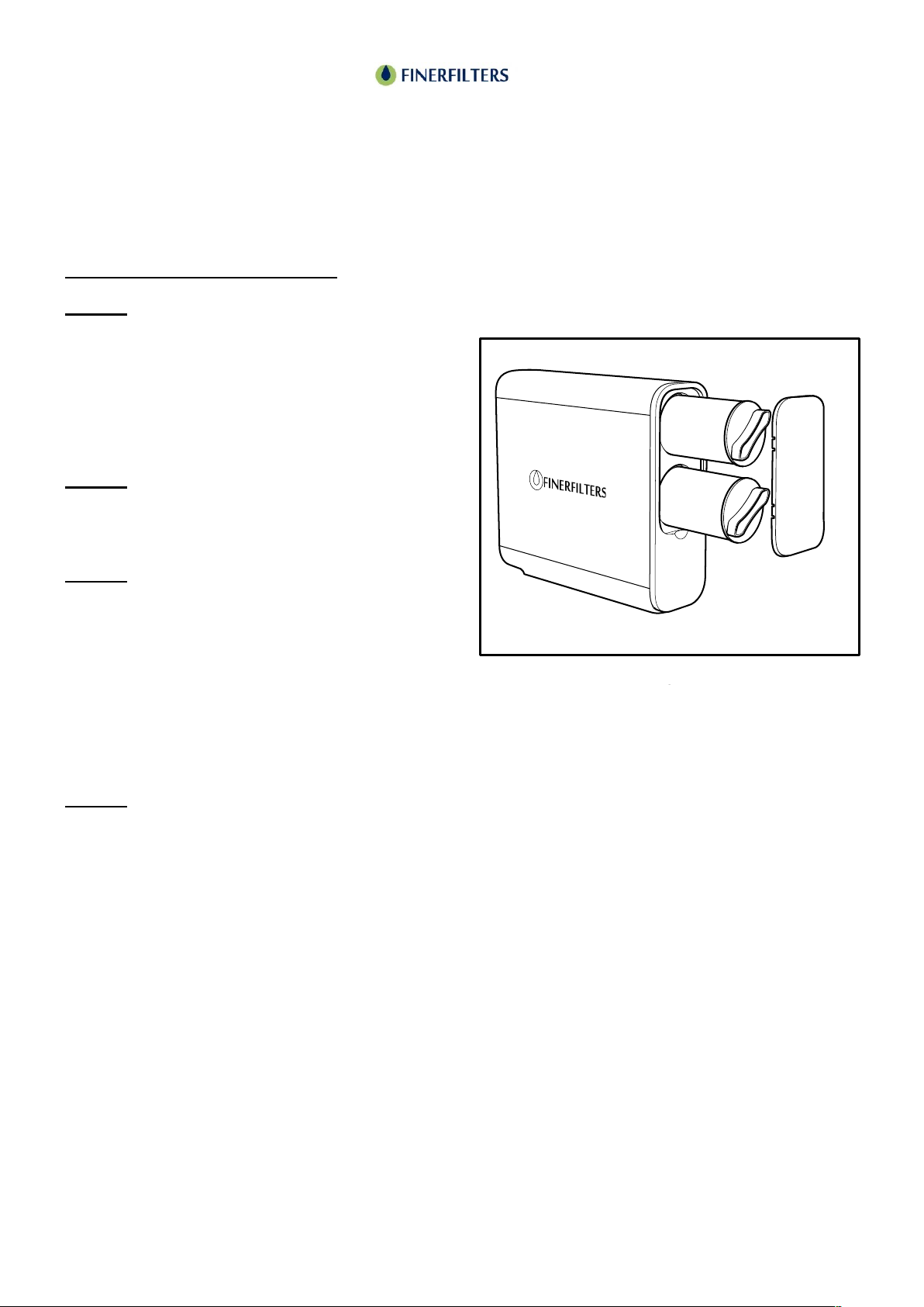
Position the RO unit where it is to be installed. The diagram below shows the various
connections that will need to be made on the back of the unit. To remove the protective plugs
push the collet ring back and at the same time pull out the plug. A video is available on our
“Finerfilters LTD” YouTube channel – “How to remove tubing from a Pushfit water filter –
Finerfilters” for a visual representation.
Recommended Tools for Installation
Variable Speed Drill: Utilized for drilling various-sized holes as needed.
3mm Drill Bit: For creating a pilot hole for the wastewater outlet.
6mm Drill Bit: For drilling the actual hole for the wastewater outlet.
25mm Hole Saw: For drilling the hole for the tap.
Pliers: For gripping and tightening components.
Phillips Screwdriver: For screwing and unscrewing components.
Utility Knife: For cutting tubing to the desired length.

Page 5
DFT8 Reverse Osmosis Filter
Preparation and Installation
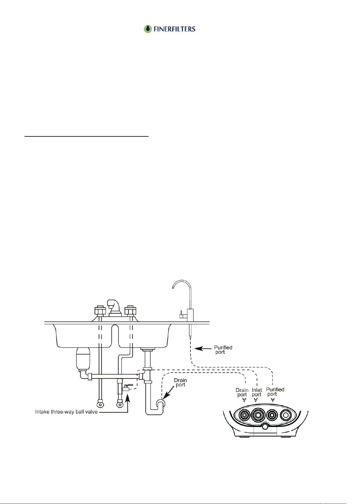
Connecting to the Main Water Supply
Please refer to the accompanying diagram
labelled "Fig 3" for visual guidance.
1. Preparing the Shut-off Valve
Assembly:
Attach the ball valve to the female nut
connection of the shut-off valve and secure
it by tightening the nut.
Connect the push-fit fitting to the male end
of the shut-off valve, ensuring the rubber
seat is properly positioned, and tighten it.
2. Measuring and Preparing the Tubing:
Measure the required length of 3/8" plastic tubing needed to link the shut-off valve to the inlet
connection on the RO unit's back.
3. Connecting the Tubing:
Remove the nut from the shut-off valve nipple and loosely fit it onto the 3/8" tubing.
Insert the tubing onto the valve nipple, then screw the nut back onto the valve and tighten it
securely.
4. Preparing the Main Water Supply:
Prior to making any cuts, ensure to turn off the water supply via the stopcock valve.
To prevent water spillage, drain the system:
Open all taps and showers in the property to allow air in as the water drains out.
There's usually a drain cock attached to the stopcock—connect a hose to it and let the water
drain into a large bowl or basin.
5. Installing the Shut-off Valve Assembly:
Cut away a 95mm section of the main water supply pipe after the stopcock valve.
Install the shut-off valve assembly to the main water pipe as demonstrated in Fig 3.
6. Finalizing the Installation:
Ensure the shut-off valve is in the OFF position.
Turn the stopcock valve back on to restore the water supply.
Fig 3
Page 6
DFT8 Reverse Osmosis Filter
Preparation and Installation
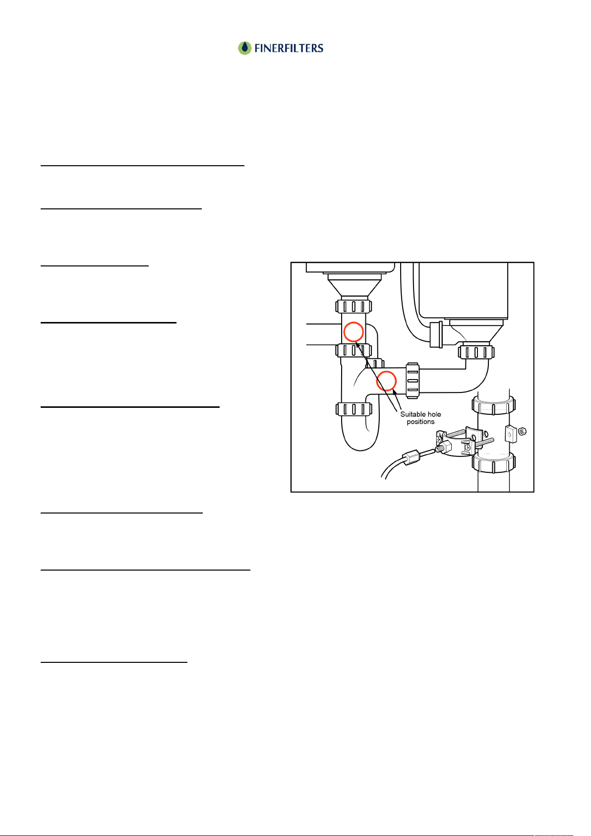
Connecting to the Waste Water Pipe
Refer to the diagram labelled "Fig 4" for visual guidance.
1. Locating the Drain Clamp:
Position the drain clamp either on a horizontal or vertical section of the pipe above the under-
sink waste trap. Mount it as low as possible to minimize drainage noise.
2. Drilling the Hole:
Drill a 1/4" hole on the front side of the pipe
as shown in Fig 4.
3. Applying the Sponge:
Remove the center piece from the black self-
adhesive sponge, then stick the sponge onto
the pipe around the hole you've drilled. Refer
to Fig 4 for positioning.
4. Assembling the Drain Clamp:
Loosely fit the two halves of the drain clamp
around the pipe using the provided nuts and
bolts.
Use a pen or pencil to align the hole in the
clamp with the hole in the waste pipe.
5. Securing the Drain Clamp:
Once aligned, tighten the bolts using a Phillips screwdriver, as depicted in Fig 4. Be cautious not
to overtighten the bolts.
6. Measuring and Cutting the Tubing:
Determine the length of tubing needed to connect the drain outlet of the RO unit to the drain
clamp.
Note: Ensure you measure enough tubing to allow for movement of the RO unit for filter
changes. Cut the tubing at right angles for a proper fit, as illustrated in Fig 5.
7. Connecting the Tubing:
Insert the tubing into the clamp, slide the locking nut up the tubing, then screw it into the clamp
and tighten securely.
Fig 4
Page 7
DFT8 Reverse Osmosis Filter
Preparation and Installation
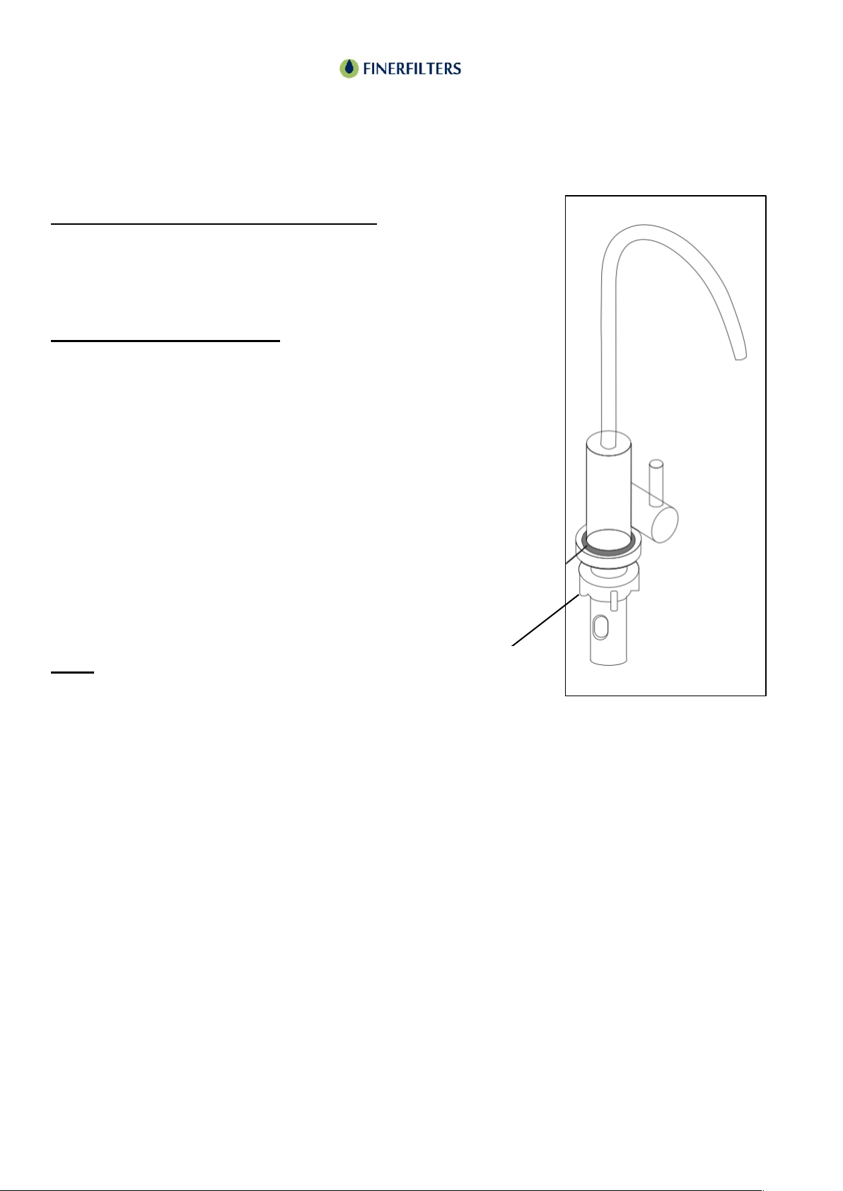
Smart Light Display Faucet Instructions:
Upon powering on the unit, the light ring on the
faucet will flash three times, displaying colours in
the sequence of blue, orange, and blue.
Filter Element Life Indicator:
Throughout the lifespan of the filter element, turning
on the faucet will illuminate the light ring in bright
blue, indicating the filter is functioning properly.
As the filter element nears the end of its lifespan (at
10% remaining life), turning on the faucet will cause
the light ring to flash blue, signalling it's near time
for a replacement.
Once the filter element life depletes to the
predetermined set value, turning on the faucet will
illuminate the light ring in red, indicating the need
for filter replacement.
Note:
The light ring will remain off when the faucet is not
in use to conserve power.
Filter indicator
light

Page 8
DFT8 Reverse Osmosis Filter
Preparation and Installation
Connecting to the RO unit.
• Push the main water, wastewater, filtered water tubes and the smart tap plug into their
appropriate positions on the back of the unit.

Page 9
DFT8 Reverse Osmosis Filter
Preparation and Installation
Setting Up and Debugging Instructions for Tankless Reverse Osmosis System
Installation Completion Verification:
• Once the installation of the system is completed, open the three-way ball valve.
• Check for any water leakage at the connections between the system and other fittings.
• Turn on the power supply.
System Flushing and Membrane Preparation:
• Turn on the faucet to initiate the flushing of the reverse osmosis membrane filter element.
• To ensure the best purification performance from the reverse osmosis membrane filter
element, adhere to the following steps:
• Turn on the pure water faucet and allow the water to flow normally for 1 hour.
• Turn off the faucet and let the system sit idle for 24 hours.
• Afterwards, turn on the pure water faucet again. Allow for 20 to 30 minutes of normal water
production before using the water. The water produced post this period is safe for
consumption.

Page 10
DFT8 Reverse Osmosis Filter
User Guide
Full Water State:
Display Screen (Light Belt): The display will remain brightly lit to indicate a full water state.
If the high voltage switch is turned off, the system enters the full water state.
Maintenance Mode:
If the system doesn’t fill up within 60 minutes of continuous water production, it will stop water
production and enter maintenance mode.
The display will show an "E1" error code and sound an alarm. The alarm will sound five times
every half an hour.
To exit maintenance mode, turn the power off and then on again.
Pure Water Quality:
The display shows the real-time TDS (Total Dissolved solids) value of the pure water, updating
every 10 seconds while water is being produced.
The TDS value will not update during the full water state.
Filter Element Life:
When the filter requires replacement, the filter indicator light will illuminate. The default timer tracks
both the cumulative usage time and the natural time of the pump.
Once the cumulative usage time reaches the system’s preset time, an alarm will sound ten times,
and the filter element indicator along with the life bar frame will flash until reset.
The filter element life indicator has a power-off memory function. If powered off and then on again
during a flashing alert, it will return to its original flashing state.
Post Water Production:
When water production stops, the membrane inside will empty and undergo a thorough rinse,
expelling approximately 380ml of wastewater.
This process is normal and ensures optimal filter performance.
Page 11
DFT8 Reverse Osmosis Filter
User Guide
Functionality:
This unit is designed for household use or similar settings, utilizing a multi-stage filtration
system based on reverse osmosis membrane technology. Once installed, simply power on the
unit, and you can initiate or halt water production by opening or closing the faucet.
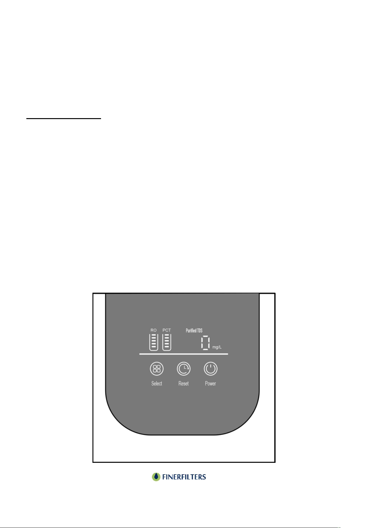
Display Instructions:
Select Key:
When the system is not in flushing mode, press and hold the select key for 3 seconds to initiate
an 18-second strong flush cycle.
Reset Key:
• Press and hold the reset key for 3 seconds to access the filter element reset function.
• Once in reset mode, press the select key to cycle through and choose the filter element to
reset.
• The chosen filter element indicator will flash, while others remain lit.
• To reset the selected filter element, press and hold the reset key for 3 seconds within a 10-
second window, thereby exiting the reset function. If no action is taken within 10 seconds,
the system exits reset mode.
Power Key:
• Tap the power key to toggle the display interface on or off, while the power indicator remains
lit.
• Note: The power button solely controls the display brightness.

Page 12
DFT8 Reverse Osmosis Filter
User Guide
Function Descriptions:
Flushing Status:
• Display Screen (Light Belt): Indicates flushing mode by flashing.
• Upon power on, an automatic 30-second flush initiates.
• Press and hold the select key for 3 seconds for an 18-second flush.
• If water production is continuous for ≥ 30 minutes without mid-cycle flushing, an automatic
18-second flush occurs upon entering the full water standby state.
• After a continuous standby time of ≥ 6 hours without flushing, an automatic 18-second flush
initiates.
•
Water Production Status:
• Display Screen (Light Belt): Indicates water production mode with a racing lantern display.
• Water production mode is activated when the high-voltage switch is closed.
Page 13

Page 14
DFT8 Reverse Osmosis Filter
Filter Replacements
Filter Element Replacement Cycle
(Recommended):
Over time, the filter element in the system accumulates impurities which can slow down the
water flow. To maintain a normal effluent rate, it's essential to replace the filter element
regularly. Assuming an average daily pure water consumption of 10 litres from municipal tap
water, with standard water temperature, pressure, and quality, the recommended replacement
cycle for each filter element is as follows:
Influencing Factors:
The life expectancy of the filter elements, including the reverse osmosis membrane, is
significantly impacted by water quality among other factors.
Actual lifespan may vary based on your local water conditions, and the below data should serve
as a reference point.
Page 15
DFT8 Reverse Osmosis Filter
Filter Replacements
Filter Element Replacement Cycle
Indicators for Replacement:
Consider replacing the filter element under the following circumstances:
The quality or taste of the filtered water deteriorates.
There's a noticeable reduction in the water flow rate. Check for potential blockages in the filter
element or membrane (ensure this isn't due to a drop in water temperature).
Severe blockages prevent water production or inhibit the flow of clean water from the system.
Reminder: Before proceeding with changing the filter element, ensure to shut off the water
supply and open the faucet to relieve any pressure in the system.
Preparation:
Run the entire machine for 3-5 minutes, then cut off the power.
Note: A small amount of residual water may flow out during the filter element replacement
process.
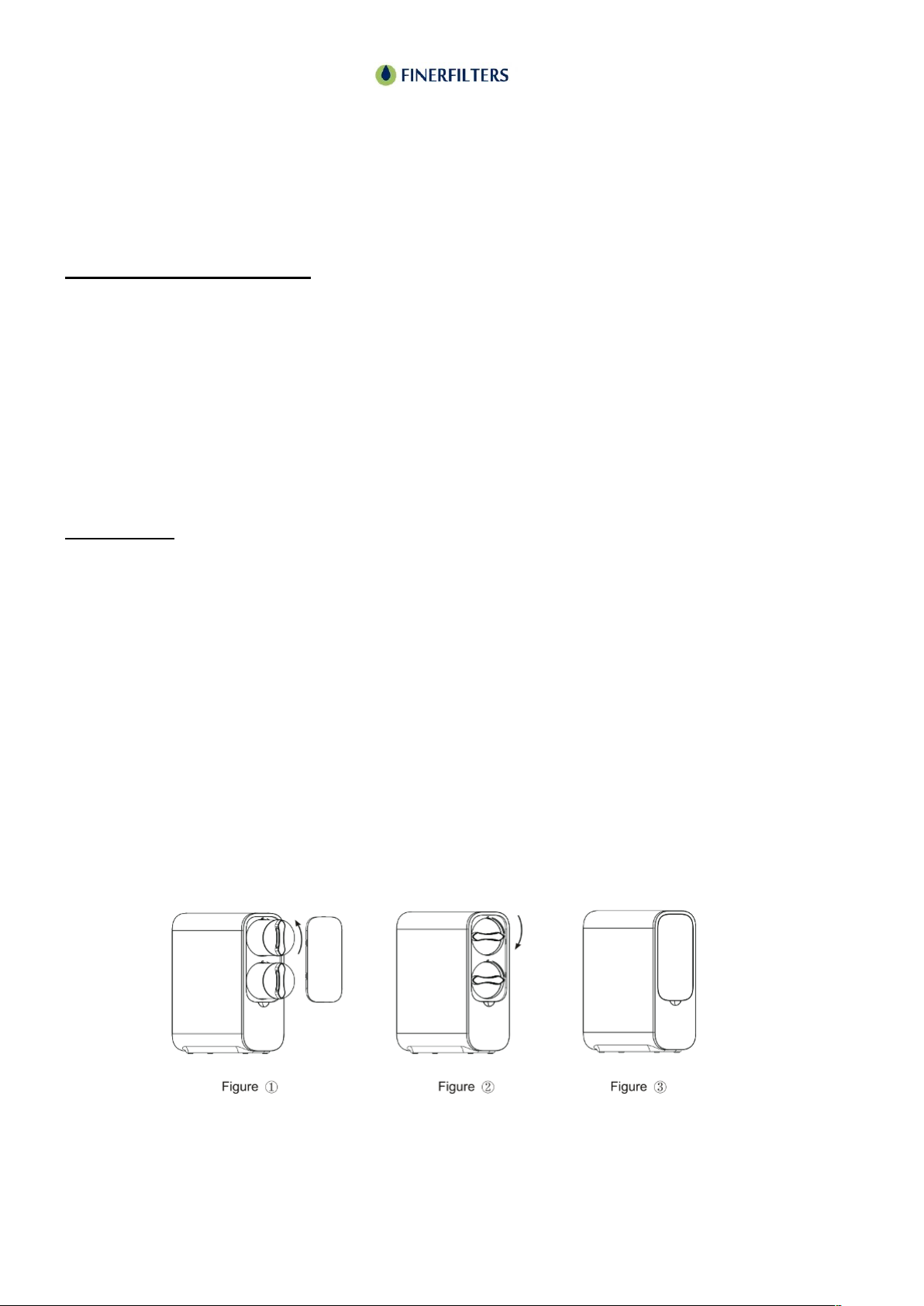
Removing the Old Filter Element:
Step 1: Adhering to the reminder, cut off both water and power supplies.
Step 2: Remove the cover plate to access the filter elements. Identify the filter element you wish
to replace. Rotate the filter element counterclockwise by hand until the arrow logo on the filter
aligns with the unlock logo (figure 1), then remove the filter element.
Step 3: After removing the filter element, use a clean towel to wipe away any remaining water in
the filter cartridge frame.
Page 16
DFT8 Reverse Osmosis Filter
Filter Replacements
Filter Element Replacement Cycle
Installing the New Filter Element:
Step 1:
Position the new filter element so that the arrow
logo on the filter element aligns with the unlock
indicator on the filter housing.
Once aligned, rotate the filter element clockwise
until the arrow logo aligns with the lock indicator.
Step 2:
Place the cover plate back onto the unit (as
depicted in Figure 3).
Step 3:
Reconnect the power supply and water source.
Press and hold the reset button for 3 seconds to
enter the filter reset program.
Tap the selection key to cycle through and select the filter element that was replaced.
Once the correct filter element is selected, press and hold the reset button for 3 seconds to
complete the reset process (you may notice a sound or a signal indicating a successful reset).
Step 4:
Press and hold the "Select" button for 3 seconds to initiate a flushing cycle.
Turn on the gooseneck faucet and allow the system to rinse for 5-10 minutes, then turn off the
faucet.
During this time, inspect the entire unit for any potential leaks to ensure a successful installation.
Fig1
Page 17

Page 18
Page 19
This manual suits for next models
1
Table of contents
Other Finerfilters Water Filtration System manuals


