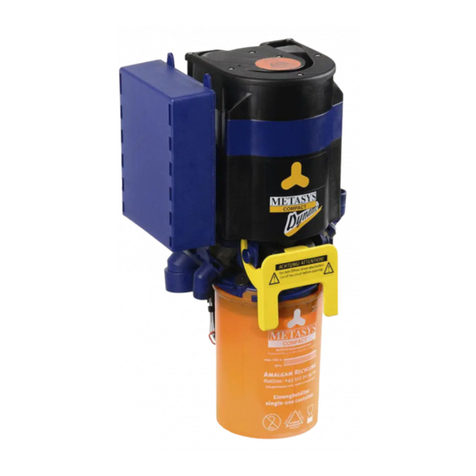
Metasys MULTI SYSTEM 1 User manual

MULTI SYSTEM TYP 1
Instruc ons for use
EN | ZK-58.203/00 | 2021-09
eIFU:
www.metasys.com/downloads

EN | Table of contents
2
Table of contents
1. Notes ....................................................................................................................................................4
1.1. General instructions............................................................................................................................................................................................................ 4
1.2. Explanation of the symbols................................................................................................................................................................................................. 4
1.3. Copyright notice.................................................................................................................................................................................................................. 5
2. Intended use........................................................................................................................................6
2.1. Indication............................................................................................................................................................................................................................. 6
2.2. Contraindication.................................................................................................................................................................................................................. 6
2.3. Target group........................................................................................................................................................................................................................ 6
3. Safety-related information .................................................................................................................7
3.1. General safety-related information...................................................................................................................................................................................... 7
3.2. Safety instructions............................................................................................................................................................................................................... 7
3.3. Warnings............................................................................................................................................................................................................................. 7
4. Product description ............................................................................................................................8
4.1. Product description ............................................................................................................................................................................................................. 8
4.2. Technical data / performance data...................................................................................................................................................................................... 8
4.3. Type plate ........................................................................................................................................................................................................................... 8
4.4. Construction........................................................................................................................................................................................................................ 9
4.5. Functional description......................................................................................................................................................................................................... 9
5. Preparation for use ...........................................................................................................................11
5.1. Transport and storage........................................................................................................................................................................................................11
5.2. Installation requirements....................................................................................................................................................................................................11
5.2.1. Assembly variants ..............................................................................................................................................................................................11
5.2.2. Pipe and hose connections ............................................................................................................................................................................... 12
5.2.3. Connection dimensions..................................................................................................................................................................................... 13
5.2.4. Filter .................................................................................................................................................................................................................. 13
5.3. Installation, assembly and commissioning........................................................................................................................................................................ 13
5.3.1. Installationandassemblyofoptionalaccessories,retrotpartsandspareparts ............................................................................................. 15
5.3.1.1. Retrottingthenon-returnvalveforcentrifugepump........................................................................................................................................ 15
5.3.2. Connecting to other devices.............................................................................................................................................................................. 16
5.4. Electronics ........................................................................................................................................................................................................................ 16
5.4.1. Electrical connections........................................................................................................................................................................................ 17
6. Use .....................................................................................................................................................18
6.1. Normal operation .............................................................................................................................................................................................................. 18
6.2. External and internal displays........................................................................................................................................................................................... 18
6.2.1. External display................................................................................................................................................................................................. 18
6.2.2. Internal display .................................................................................................................................................................................................. 18
6.3. Error messages................................................................................................................................................................................................................. 19
7. Care and maintenance......................................................................................................................20
7.1. Regular cleaning measures .............................................................................................................................................................................................. 20
7.1.1. Daily cleaning with GREEN&CLEAN M2 .......................................................................................................................................................... 20
7.1.2. Cleaning the centrifuge inlet probe.................................................................................................................................................................... 20
7.2. Maintenance and service.................................................................................................................................................................................................. 21
7.2.1. Replacement of the collection container ........................................................................................................................................................... 21
7.2.2. Disposal of the collection container................................................................................................................................................................... 23
7.2.3. Normal operation test........................................................................................................................................................................................ 24
7.2.4. 1-year service kit ............................................................................................................................................................................................... 25
7.2.5. 5-year service kit ............................................................................................................................................................................................... 26
7.2.5.1. Visual check of the centrifuge ........................................................................................................................................................................... 26
7.2.6. Replacement of module 2 ................................................................................................................................................................................. 27
7.2.7. Replacement of module 3 ................................................................................................................................................................................. 27
7.2.8. Replacement of the magnetic valve .................................................................................................................................................................. 27
7.2.9. Replacement of inlet main body........................................................................................................................................................................ 28
8. Decommissioning .............................................................................................................................29
8.1. Disassembly...................................................................................................................................................................................................................... 29
8.2. Recycling and disposal ..................................................................................................................................................................................................... 29
9. Annex .................................................................................................................................................30
9.1. REF numbers and scope of delivery................................................................................................................................................................................. 30
9.1.1. Accessories, service kits, collection containers and spare parts....................................................................................................................... 30
9.1.2. Accessories....................................................................................................................................................................................................... 30
9.2. Warranty conditions .......................................................................................................................................................................................................... 38
9.3. Change history.................................................................................................................................................................................................................. 39

eIFU | EN
3
eIFU
eIFU: www.metasys.com/downloads
DE, EN, FR, IT, BG, CS, DA, EL, ES, ET, FI, HR, HU, LT, LV, NL, NO, PL, PT,
RO, SK, SL, SV
e-mail [email protected]
Order number ZK-58.203/00
If you would like to request a printed copy of the instructions for use, please contact us at [email protected] or use the order form at www.metasys.com/downloads
A hardcopy of the instructions for use will be made available to you free of charge and within seven calendar days of receipt of the request.
Translations
Translation of the original instructions for use
Tetras GmbH
Sirius Business Park, Rupert-Mayer-Str. 44, 81379 Munich, Germany
Images
The images contained in these instructions for use are for reference and may differ from the actual appearance of the product.

EN | Notes
4
1. Notes
1.1. General instructions
METASYS can only guarantee the safety, reliability and performance of the dental device if the following instructions are adhered to:
> The product is only to be used in accordance with the instructions for use.
> During maintenance and service work (inspection, service, repair, replacement), only use original replacement parts.
>Allmanufacturerspecicationsforthetreatmentunitstowhichthedeviceisconnectedmustbeobserved.
>Aftercommissioning,completetheproofofinstallationandsendthistoMETASYSinordertodenethewarrantyperiod.
> All maintenance and service work must be entered into the device logbook.
>Onrequestbyanauthorisedtechnician,METASYSwillprovidealldocumentationthatmaybeofusetotechnicallyqualiedpersonnelduringmaintenance
and service works
>METASYSacceptsnoresponsibilityfordamagethatmayariseduetoexternalinuences(defectiveinstallation),usingincorrectinformation,improperuseof
the dental device, or maintenance and service works being carried out improperly.
>The user must familiarise himself/herself with how to operate the dental device and ensure that the dental device is in good condition each time before
operating it.
Important: Read the accompanying documents of the device carefully before installation, commissioning and use and keep them for the entire service life of the
product!
1.2. Explanation of the symbols
CE mark End device ready for operation Use eye protection
Medical device Loudspeaker Use mouth and nose protection
REF/order number Sound Unplug from mains
Serial number Inclination / slope General warning sign
Manufacturer Maximum installation altitude Warning of electrical voltage
Date of manufacture Blower / fan iInformation
Follow instructions for use On | Off Download
eIFU:
www.metasys.
com/downloads
Follow instructions for use with
reference to eIFU
Separate collection of electrical/
electronic equipment (WEEE) Do not cut
Protective earthing Maintenance / service
Temperature limit Protection class II Stop operation
Caution / attention Applied part type BF Protect from heat / Protect from
sunlight
Beware of electric shock
Mark of conformity per para. 22
section 4 Lower Saxony Building
Regs
Protect from moisture / Store in a
dry place
Humidity limit Responsible for the translation Fragile
Tanklled Observe instructions for use Package orientation at the top

Notes | EN
5
Fault on end device Use hand protection Stacking limit n = (quantity)
1.3. Copyright notice
All names and contents are protected by copyright. Distribution, duplication or alternative use of this document is only permitted with the written consent of
METASYS Medizintechnik.

EN | Intended use
6
2. Intended use
The MULTI SYSTEM TYP 1 is a two-stage, single unit amalgam separator with integrated air/water separation and place selection valve for separating amalgam
from waste water from dental treatment units.
2.1. Indication
Not applicable.
2.2. Contraindication
Not applicable.
2.3. Target group
Thedeviceshallbeusedbytrainedandqualiedpersonnelexclusively.

Safety-related information | EN
7
3. Safety-related information
3.1. General safety-related information
All serious incidents related to the device must be reported to the manufacturer and the competent authority of the Member State where the user and/or the patient
is resident.
3.2. Safety instructions
Assembly,modicationsorrepairsmayonlybecarriedoutbyauthorisedqualiedpersonnelwhoguaranteecompliancewiththeEN60601-1standard(international
standard on Medical Electrical Equipment and Systems, in particular part 1: General requirements for basic safety).
The electrical installation must comply with the regulations of the IEC (International Electrotechnical Commission).
Medical devices should be handled with care with regard to electromagnetic compatibility. Special safety measures must therefore be taken.
Thedeviceisnotsuitableforoperationinexplosiveareasorinammableatmospheres.
3.3. Warnings
Danger Warning of a danger that will directly result in serious injury or death
Warning Warning of a danger that can result in serious injury or death
Caution Warning of a danger that can result in minor injury
Attention Warning of a danger that can result in extensive damage to property

EN | Product description
8
4. Product description
4.1. Product description
MULTI SYSTEM TYP 1 is a two-stage, single unit amalgam separator with integrated, static air/water separation and place selection valve.
4.2. Technical data / performance data
Height [H]
Width [W]
Depth [D]
MULTI SYSTEM TYP 1
Power supply 24 V AC
Frequency 50 / 60 Hz
Max. current consumption 2 A
Max. power consumption 46 VA
Max. ambient temperature 40 °C
Max.liquidowrate 3.0 l/min via the spittoon; 1.5 l/min via the suction side
Negative pressure range 80 mbar - 250 mbar
Separation rate 98.60 %
Collection container volume 300 cm3
Dimensions (H x W x D) 305 x 210 x 104 mm
Dimensions with cover (H x W x D) 340 x 280 x 185 mm
Class MD class 1
DIBT approval number Z-64.1-4
Possible suction systems Wet or dry suction systems
4.3. Type plate
MULTI SYSTEM TYP 1 Built-in version:
The type plate is located on module 1 and is visible when module 2 is removed (to do this, tilt the locking bracket on
module 2 upwards and remove module 2).
MULTI SYSTEM TYP 1 with cover:
The type plate is located on the cover next to the external display (push the lid of the cover upwards) as well as on
module 1 and is visible when module 2 is removed (see built-in version).

Product description | EN
9
4
11
6
2
1
3
10
8
7
9
5
12
13
Example picture
1 Device description
2 Connection data
3 Registration number Deutsches Institut für Bautechnik (DIBT) (German Institute of
Construction Technology)
4 Mark of conformity per para. 22 section 4 Lower Saxony Building Regs
5 Separate collection of electrical/electronic equipment (WEEE)
6 Follow instructions for use
7 Date of manufacture
8 Serial number
9 Manufacturer
10 REF/order number
11 CE mark
12 Protection class II
13 Applied part type BF
4.4. Construction
Module 1 Module 2 Module 3
Central fastening element:
Air, water and electrical connections
Wall mount
Main board
Diagnostic board
Filter unit
Air/water separation:
Collection container
Separation unit
Place selection valve
Centrifuge:
Dynamic amalgam separation
Cover
Cover (optional)
4.5. Functional description
Lifting a suction hose opens the place selection valve. The suction current is fed into module 2, where the air/water separation takes place by means of the cyclone
principle.
The dry air leaves the system via the place selection valve to the suction motor. The liquid and solid components of the suction current enter the collection container
belowtheseparation,whichisalsotherststageofamalgamseparation.
While the coarser particles sediment in the collection container, the liquid level rises depending on the suction volume. As soon as a certain level is reached,
the pump motor is started for a certain period of time via a conductivity probe. The pump conveys the pre-cleaned liquid into the centrifuge, the second stage of
amalgam separation, which is also started via a probe. Waste water coming from the spittoon is fed directly into the centrifuge. The heavy parts are held in the run
against the walls of the double-chamber centrifuge, while the clean water exits via the upper edge of the outer centrifuge into the drain. As soon as the probe no
longer makes contact, the centrifuge stops abruptly after a short run-on time.
Thecontinuingrotationofthewatercolumnushestheheavyparticlesintothepumplocatedbelowthecentrifuge.Themotorstartsagainafterashortwaitingtime
and thus pumps the heavy parts with the residual water quantity into the collection container.

EN | Product description
10
1
5
2
4
6
9
8
3
71 Place selection valve
2 Module 2 (air/water separation)
3 Exhaust air to suction motor
4 Collection container
5 Pump motor
6 Centrifuge
7 Spittoon waste water input
8 Waste water output
9 Pump

Preparation for use | EN
11
5. Preparation for use
5.1. Transport and storage
Thedeviceisshippedintwopolystyreneshellsxedtogether.Thisoriginalpackagingmustbeusedforanyonwardandreturntransport.Thedevicemustalways
be transported and stored in an upright position. The device must be transported to the installation site in a completely packed state. After unpacking the device,
check for completeness and possible transport damage.
70 °C
0 °C
Transport and storage temperature
80 %
0 %
Transport and storage humidity limitation
5.2. Installation requirements
40 °C
10 °C
Operating temperature: 10°C to 40 °C
70 %
0 %
Humidity limit max. 70 %
≤3000m
Max. 3,000 m above sea level
> The following space requirement must be provided for the installation: H x W x D = 350 mm x 215 mm x 120 mm
> To avoid vibrations, use only the three holes on module 1 to attach to load-bearing parts of the treatment unit! (Do not remove vibration inserts!)
> The device must be able to swing freely and must not have any contact with other parts of the treatment unit (cables, hoses, covers, etc.).
Caution:
Acontactprotectionplatemustbettedbehindmodule1ifthesubsurfaceiselectrically
conductive!
5.2.1. Assembly variants
Installation in the spittoon
Direct integration of the device into the spittoon should be used as the preferred solution, as the tubing
routes to the device can be kept as short as possible.
In the spittoon, ensure vibration-free suspension of the device from supporting parts of the treatment unit.

EN | Preparation for use
12
Installation in the behind the patient‘ head
If there is no spittoon at the treatment chair and the suction system is located behind the head of the patient,
the device can be installed inside a cabinet.
In this case, the connection opening for the spittoon drain must be closed with a blind plug.
Split version
For work places which have suction behind the patients’ head as well as a spittoon, the amalgam separator
can be split into two parts.
Module 1 and module 2 are mounted in the rear head cabinet near the hose storage.
Module3,thecentrifuge,isttedintothespittoonornexttothedentalunit’sconnectionboxwithaspecial
bracket.
Both parts of the unit are connected to each other via cables in the ground. For this purpose, there must be
an empty conduit of at least ø 20 mm between the connection box and the back-of-the-head cabinet. The
cable length must not exceed 3.5 m!
Set-up with cover
If it is not possible to install the device directly in the treatment unit, the set-up can also be carried out in
the optionally available cover.
The cover should be mounted on the connection box of the treatment unit. The external display and a
transformer are already integrated in the cover.
5.2.2. Pipe and hose connections
1
2
43
5
1 Connection for spittoon drain hose
2 Connection for suction hose (for hose storage)
3 Connection for suction hose (to suction machine)
4 Connection for drain hose (clean water outlet)
5Connectionforoverowhoses(e.g.tumblerller)
Attention:
Unused connections must be sealed with blind plugs!
The hose routes leading to the device must be kept as short as possible to prevent pre-sedimentation.
Dirty dental hoses must be replaced during installation and disposed of by an approved disposal company.
The device must be connected to the sewage pipe via an odour trap.
Thewastewatermustbeabletoowfreely,astheseparationefciencyisnotguaranteedintheeventofabackwater.

Preparation for use | EN
13
Water jet operated saliva ejectors must be shut down due to high water consumption.
Theushingofthespittoonmustbelimitedbymeansofatimerorbuttontomax.30secondsatamax.waterowof3l/mintoenablethecentrifugetostop.
For matching hose nozzles and adapters see 9.1.1. Accessories, service kits, collection containers and spare parts.
5.2.3. Connection dimensions
ø 26
ø 15
ø 26
ø 16
ø 22
5.2.4. Filter
Ifnotpresentinthehosestorage,apre-lterwithameshsizeofmax.1mmmustbeinstalledonthesuctionsideoftheamalgamseparator.Thepre-ltermust
be easily accessible for the practice staff.
There must be a coarse sieve in the drain of the spittoon. This must have a mesh size of max. 3 mm and must not be removed while the amalgam separator is in
operation.
2
1
1 Coarse sieve (spittoon)
2Pre-lter
5.3. Installation, assembly and commissioning
1
Read the instructions carefully before installation and commissioning!
Meet spatial requirements see 5.2. Installation requirements

EN | Preparation for use
14
2Check the coarse sieve in the spittoon
3Installthepre-lter(ifnotpresentinthehosestorage)
MULTI SYSTEM TYP 1 Built-in version
4Fit a contact protection plate behind module 1 (if the subsurface is electrically conductive)
5Connect the spittoon drain hose
6Connect the drain hose
7Connect the suction line from the hose storage (suction hose) and to the suction machine (suction
hose)
MULTI SYSTEM TYP 1 with cover
8
Placement of the MULTI SYSTEM TYP 1 with cover:
Spittoon drain above I (red), amalgam separator drain below O (yellow), min. 700 mm free height
(green) for hose storage
I
O
Free height
9Connect the spittoon drain hose
10 Connect the suction line from the hose storage (suction hose)

Preparation for use | EN
15
11 Connect the suction line to the suction machine (suction hose)
12 Connect the drain hose
13 Connect electrical connections (see 5.4. Electronics)
14 Switch on the device via the device or practice main switch.
ThecentrifugeoftheMULTISYSTEMTYP1startsuptwicebrieyandstopsabruptly(self-test).
O
I
15 When LED 1 lights up green, the amalgam separator is ready for operation (for a description of the
external display, see 6.2.1. External display).
16
Inform the dentist about product function, operation, care and warranty conditions.
EQUIPMENT LOGBOOK
METASYSMedizintechnik GmbH | Florianistraße 3, 6063 Rum bei Innsbruck, Austria | Phone: +43 512 205420 | [email protected] | www.metasys.com
Berechtigt zur Garantie
Bitte ausf üllen und retournieren
MONTAGEMELDUNG
Entitles to warranty
Please complete and return
INSTALLATION PROOF
Für den Techniker |
For the technician
Gerät, Seriennummer | Equipment, Se rial no.
Datum Inbetriebnahme | Date of first operation
Techniker | Technician
E-Mail
Depot | Dental Dealer
Für die Zahnarztpraxis |
For the dental surgery
Bitte bestätigen Sie, dass Sie Ihr Technikerüber folgende wichtige Punkte
informiert hat:
Please confirm that your technician has informed you about the following
important points:
Produktfunktion, -bedienung und Pfl ege
Fonctionnement, utilisation et entretien du produit
Garantiebestimmungen: Einhalten der Wartungsintervalle, Betrieb und
Reinigung mit vom Hersteller empfohlenen Präparaten, Wartungsdoku-
mentation und Rücksendung der Montagemeldung
Warranty guidelines: Keeping service intervals, Operation and cleaning
with preparations recommended by the manufacturer, Service documen-
tation, Return of installation proof
Zahnarztpraxis | Dental surgery
E-Mail
d d m m y y y y
Händler | Dealer
Depotstempel &Unterschrift Dental Dealer Stamp&Signature
Gerätestandort | Place of installation
Den umseitigen Hinweis zum Datenschutz habe ich zur Kenntnis genommen.
I have taken note of the overleaf note on data protection.
Praxisstempel &Unterschrift Dental Surgery Stamp &Signature
installation@metasys.com
Fax: +43 512 205420-1123
CS, ES, FI, FR, IT, PT,... : www.metasys.com
META Air 250, DM-001234
x xx x 2 0 2 0
Max Mustermann
Depot Max Mustermann
Dr. Hans Zahn
Depot Max Mustermann
Musterstraße 10, 1010 Wien
Österreich
www.mustermann.at
Dr. Hans Zahn
Zahnstraße 2, 1010 Wien
Österreich
www.drzahn.at
Fill in the installation proof and device logbook and return them to METASYS (installation@metasys.
com)
17 Carry out a normal operation test see 7.2.3. Normal operation test
5.3.1. Installation and assembly of optional accessories, retrofi t parts and spare parts
Assembly,modicationsandrepairsmayonlybecarriedoutexclusivelybyauthorisedspecialistpersonnel(see3.2.Safetyinstructions)!
TheMETASYStechnicalcustomerserviceisalsoavailableforfurtherinformationandassistanceincarryingoutrepairs,retrotting,
fault analyses, etc.
5.3.1.1. Retrofi tting the non-return valve for centrifuge pump
Suction noises at the spittoon can be caused by excessive negative pressure in the suction machine, or by straight and short connecting lines between the spittoon
and the amalgam separator.

EN | Preparation for use
16
IfsuctionnoisesoccurinconnectionwiththeMULTISYSTEMTYP1,thenegativepressure(max.250mbar)andtheairintakevalveshouldbecheckedrst.If
the noises persist despite correct negative pressure, they can be avoided by means of the external non-return valve.
1Preparation:
Cut the connecting line from the centrifuge pump to module 2 approx. 5 cm from the centrifuge.
2
Assembly:
Connect the central connection of the non-return valve to the elbow - module 2.
Connect the second connection to the centrifuge pump.
3
Function test:
The following points must be checked as part of a correct function test. If errors occur at any of these points, follow the instructions
in step 4.
No water may be drawn from the centrifuge pump into module 2 during suction operation.
There must be no noise at the external non-return valve during suction.
Whenthecentrifugeispumpingback,theremustbeanormalwaterow.
When the centrifuge is pumping back, no water must escape from the non-return valve.
4
Adjustment:
The lower part must not be connected too tightly! This can be corrected by rotating the lower part
slightly (maximum 1/4 turn to the left or right). Then carry out the function test (step 3) again.
5.3.2. Connecting to other devices
When connecting the METASYS device to other devices or systems, hazards can arise. It must therefore be ensured that no hazards arise for the user or the
patientandthattheenvironmentisnotaffected.Thespecicationsofthemanufacturerofthedeviceorsystemtobeconnectedmustbeobserved.
5.4. Electronics
Themainsconnectionmayonlybecarriedoutbyaqualiedelectrician.Theelectricalinstallationmustbecarriedoutinaccordancewiththeapplicablelocal
regulations. Before connecting to the mains, compare the rated voltage on the device type plate with the mains voltage.

Preparation for use | EN
17
5.4.1. Electrical connections
6
5
1
4
32
1 Main board
2 Diagnostic board
3 Module 2
4 Module 3
5 External display
6 Hose storage switch and suction system isolating relay
SV1 Connector for centrifuge inlet probe
SV2 Connector for centrifuge motor
SV3 Connector for power supply (24 V AC)
SV4 Connector for external display
SV5 Connection to the diagnostic board (power supply for motor and magnetic valve in
module 2)
SV6 Connection to the diagnostic board (probes in module 2)
SV7 Connector for suction signal (12 - 24 V AC or DC)
F1 Main fuse MULTI SYSTEM TYP250/T 3, 15 A/UN 250 V/ ICN 35 A
F2 Fuse MST250/T 1.6 A/UN 250 V/ ICN 35 A for pump motor in module 2
iRemoving the jumpers on J1, J2 and J3 causes a better response of the probes at low water conductivity.
Danger:
The supply voltage must be taken from a safety transformer that complies with the requirements of IEC 601-1 / VDE 0750 Part 1 / DIN
EN 60601-1 and IEC 60742 + A1 / DIN EN 60742.
Danger:
Fuses may only be replaced by the same type!

EN | Use
18
6. Use
6.1. Normal operation
Ensure that the device is switched off at least 1 x per working day for level measurement. The 24 V AC power supply must be
connected after the device’s or practice‘s main switch.
O
I
6.2. External and internal displays
6.2.1. External display
12
4
3
1 LED 1 Lights up green Ready for operation
2 LED 2 Flashing red Centrifuge malfunction
3 LED 3 Lights up yellow
+ buzzer tone switchable via RESET
Level indicator: Container 95% full
Lights up yellow
+ buzzer tone that cannot be switched
off via RESET
Level indicator: Container 100% full
4 RESET No colour RESET button
When the container is 95% full, the buzzer tone can be switched off by pressing the
RESET button.
6.2.2. Internal display
1 Signal 1 Suction signal Suction hose lifted off
(12-24 V AC or DC at connector SV7)
2 Signal 2 Magnetic valve in module 2 The magnetic valve in module 2 is actuated
(“Emergency stop” probe not activated)
3 Signal 3 Pump module 2 The pump in module 2 is actuated
4 Signal 4 Centrifuge inlet probe The centrifuge inlet probe has contact

Use | EN
19
6.3. Error messages
Assembly, modications and repairs may only be carried out exclusively by authorised specialist personnel (see 3.2. Safety
instructions)! The METASYS technical customer service is also available for further information and assistance in carrying out repairs,
retrotting,faultanalyses,etc.
Error message Possible cause Countermeasures
LED2ashingred,centrifugemalfunction Centrifuge defective
Switch the main switch off several times and
switch it on again after a short pause. If the control
lamp lights up again after a short time, notify your
service technician.
LED 3 lights up yellow + buzzer tone can be
switched off via RESET Collection container 95% full
Collection container replacement recommended,
continued operation up to 100% possible.
The buzzer tone can be switched off by pressing
the RESET button. LED 3 remains lit up as a
reminder. The buzzer sounds again each time the
main switch is switched on.
(see 7.2.1. Replacement of the collection container
and 7.2.2. Disposal of the collection container)
LED 3 lights up yellow + buzzer tone cannot be
switched off via RESET Collection container 100% full
Collection container must be replaced. Further
work is not possible due to the blocking of the
place selection valve.
(see 7.2.1. Replacement of the collection container
and 7.2.2. Disposal of the collection container)
Centrifuge does not switch off automatically and is
continuously in operation Short circuit of the centrifuge inlet probe
Cleaning or replacement of the centrifuge inlet
probe (see 7.1.2. Cleaning the centrifuge inlet
probe)
No visualisation on external display
Centrifuge does not start Centrifuge probe dirty or defective Clean centrifuge probe, check connections on
circuit board and contacts
Suction current is not released Magnetic valve (module 2) defective Clean or replace the magnetic valve (see 7.2.8.
Replacement of the magnetic valve)
Bubble formation in the container when pump
(module 2) is in operation
Sieve for pump or water brake missing or
detached Retorreplacesieveorwaterbrake
Pumpingcapacitynotsufcient Sieve for pump missing or detached Reassemble or replace the sieve
Pump (module 2) does not start Pump defective, probes dirty or defective
Replace module 2 completely (see 7.2.6.
Replacement of module 2) or clean probes (see
7.1.2. Cleaning the centrifuge inlet probe, steps
3-6)

EN | Care and maintenance
20
7. Care and maintenance
7.1. Regular cleaning measures
Fortrouble-freeoperation,brieyushthespittoonaftereachtreatment,andusheachsuctionhosewithcoldwatertoremoveresiduesfromthelines.
The following cleaning measures must be carried out regularly:
Measure Interval
Cleaning and disinfection of the suction
system
2 x daily see 7.1.1. Daily cleaning with GREEN&CLEAN M2
Empty and clean the lter drawer At least 1 x per week, depending on workload,
emptying may also be necessary daily
Remove,emptyandcleanthelterdrawer.
Collect the residues containing amalgam from the
lterdrawerinasuitablecontainer.
Cleaning the centrifuge inlet probe If required & in case of malfunction see 7.1.2. Cleaning the centrifuge inlet probe
Container replacement If required / at least 1 x per year See 7.2.1. Replacement of the collection container
and 7.2.2. Disposal of the collection container
7.1.1. Daily cleaning with GREEN&CLEAN M2
2 x daily (noon/evening) and after surgical interventions, disinfection must be carried out with the prescribed disinfectant and cleaning agent GREEN&CLEAN M2.
Ideally, GREEN&CLEAN M2 should be used prior to the treatment unit remaining at a standstill for extended periods (lunchtime, end of the day or holidays).
For information on use and safety instructions, see the GREEN&CLEAN M2 instructions for use.
7.1.2. Cleaning the centrifuge inlet probe
1Switch off the main switch.
O
I
2Tilt the locking bracket on module 2 upwards and take out module 2.
3Pulltheprobeoutofthelterhousing.
Table of contents
Other Metasys Water Filtration System manuals
Popular Water Filtration System manuals by other brands

Clack
Clack CB1054/EN Installation, operation & maintenance manual

Vivreau
Vivreau PURITY 450 Quell ST manual

Spirax Sarco
Spirax Sarco 5800 Series Installation and maintenance instructions

Radioddity
Radioddity LPFX7 user manual

Grayl
Grayl TI TITANIUM ULTRAPRESS quick start guide

KRUEGER
KRUEGER CRFF-E Installation operation & maintenance

Quincy Compressor
Quincy Compressor QED-1250 Instruction book

Evolution Aqua
Evolution Aqua evo15 Installation and operating manual

Axeon
Axeon Hydrogen user manual

Forbes
Forbes ENHANCE GREEN RO user manual

Schenker
Schenker SMART 30 Installation, use and maintenance manual

PondXpert
PondXpert Triple Action Evolve 4500 How to set up