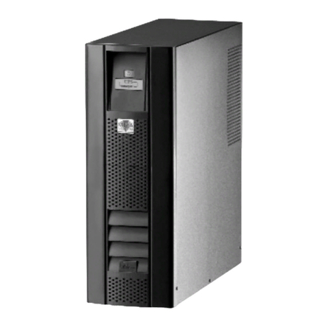
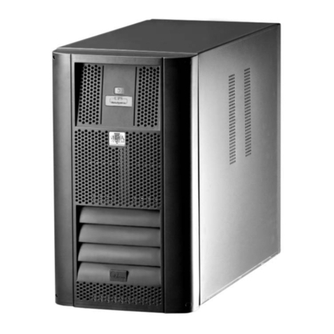
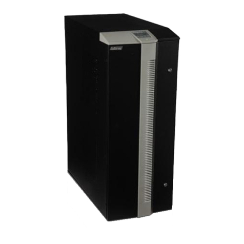
MetaSystem ARCHIMOD 20 Operating instructions

®
ARCHIMOD
Operating and Maintenance Manual
Rev. September 2010
Code 5040275001
The original of this document is drawn up in the Italian language


Operating and Maintenance Manual
code 5040275001 Rev. September 2010
Index of Contents
GENERAL INDEX ........................................................ A
CERTIFICATION OF CONFORMITY....................... D
1. FOREWORD .......................................................... 1-1
1.1 Overview ........................................... 1-1
1.2 Purpose of the manual....................... 1-2
1.3 Where and how to keep the manual ... 1-2
1.4 Manual update................................... 1-2
1.5 Collaboration with the user ................ 1-3
1.6 Manufacturer ..................................... 1-3
1.7 Responsibilities of the manufacturer
and guarantee ................................... 1-3
1.7.1 Guarantee terms................................ 1-4
1.7.2 Extension of the guarantee and
maintenance contracts....................... 1-4
1.8 Copyright........................................... 1-4
2. TECHNOLOGICAL DESCRIPTION .......................... 2-1
2.1 ARCHIMOD®technology.................... 2-1
2.2 Features ............................................ 2-2
2.3 Models .............................................. 2-3
2.4 Technical specifications ..................... 2-6
2.5 Communication devices ..................... 2-11
2.5.1 RS232 serial ports ............................. 2-11
2.5.2 Relay interface .................................. 2-11
2.5.3 Logic level interface........................... 2-12
2.5.4 Communications slot ......................... 2-13
3. SAFETY PROVISIONS ............................................ 3-1
3.1 General notes.................................... 3-1
3.2 Symbols ............................................ 3-1
3.3 Reference standards ......................... 3-1
3.4 Definitions of ‘operator’ and
‘specialized technician’ ...................... 3-2
3.4.1 Qualification required to the operator . 3-2
3.4.2 Qualification required to the
specialized technician........................ 3-2
3.5 Individual protective gear................... 3-3
3.5.1 Gear to wear...................................... 3-3
3.6 Indications of danger in the work place 3-4
3.6.1 Indications on board the equipment ... 3-4
3.7 Residual risks .................................... 3-4
3.8 General warnings .............................. 3-5
3.9 Emergency interventions ................... 3-6
3.9.1 First aid interventions ........................ 3-6
3.9.2 Fire-prevention measures .................. 3-6
A

Operating and Maintenance Manual
code 504275001 Rev. September 2010
4. UNPACKING .......................................................... 4-1
4.1 Visual inspection................................ 4-1
4.1.1 Checking the equipment and
accessories supplied ......................... 4-1
4.2 Positioning......................................... 4-1
4.3 Positioning and unpacking ................. 4-2
4.4 Checking the contents of the pack ..... 4-3
4.5 Handling ............................................ 4-3
4.6 Storing............................................... 4-3
4.6.1 UPS................................................... 4-3
4.6.2 Batteries............................................ 4-3
5. INSTALLATION........................................................ 5-1
5.1 Safety rules and regulations .............. 5-1
5.2 Electrical connections ........................ 5-1
5.2.1 Safety recommendations ................... 5-2
5.2.2 Preliminary operations ....................... 5-2
5.2.3 Connecting the loads ......................... 5-2
5.2.4 Installing the ARCHIMOD®BATTERY. 5-3
5.2.5 Protections ........................................ 5-4
5.2.6 Earthing............................................. 5-4
5.2.7 Connecting the power supply............. 5-4
5.2.8 Wiring................................................ 5-5
5.2.9
Emergency Power Off (Remote E.P.O.) 5-6
5.3 Wiring diagrams................................. 5-7
6. CONFIGURATION AND START-UP.......................... 6-1
6.1 Input configuration............................. 6-1
6.2 Output configuration .......................... 6-1
6.3 Checks prior to switching on .............. 6-2
6.4 Starting procedure ............................. 6-2
7. CONTROL PANEL ................................................... 7-1
7.1 ‘Service Mode’ function...................... 7-2
7.2 Main menu and submenus ................. 7-2
7.2.1 UPS status ........................................ 7-3
7.2.2 UPS settings...................................... 7-5
7.2.3 Power Modules.................................. 7-7
7.2.4 Events ............................................... 7-9
7.2.5 Tools ................................................. 7-9
7.2.6 Turning the single output phases on
and off .............................................. 7-9
7.2.7 Shutting down the UPS ARCHIMOD . 7-9
8. DIAGNOSTICS ........................................................ 8-1
8.1 Luminous and acoustic signals .......... 8-1
8.2 Messages .......................................... 8-2
9. MAINTENANCE....................................................... 9-1
9.1 Introduction ....................................... 9-1
9.2 Preventive maintenance .................... 9-1
9.3 Periodical checks............................... 9-2
9.3.1 Preparing the UPS for maintenance.
Forced bypass mode ......................... 9-2
9.4 Hot-swap replacing of power modules
or adding new modules...................... 9-3
9.5 Preparing the UPS for maintenance in
the manual maintenance by-pass mode 9-4
9.5.1 Manual by-pass mode........................ 9-4
9.5.2 Replacing a power module or adding
new modules ..................................... 9-4
9.5.3 Exiting maintenance by-pass ............. 9-5
9.6 Installing/replacing battery boxes....... 9-5
B

Operating and Maintenance Manual
code 5040275001 Rev. September 2010
10. DISMANTLING ...................................................... 10-1
10.1 Disposing of the batteries .................. 10-1
10.2 Dismantling the UPS.......................... 10-1
10.3
Disposing of the electronic components
.. 10-1
11. TABLES .......................................................... 11-1
12. NOTES .......................................................... 12-1
C

Operating and Maintenance Manual
code 504275001 Rev. September 2010
D
Council Directives applied: 73/23/EEC amended with directives 93/68/EEC
89/336/EEC amended with directives 92/31/EEC
93/68/EEC
Standards to which conformity is declared: EN 62040-1-1, EN EN 62040-3
Manufacturer: Meta System S.p.A.
Address: Via Majakovskij, 10/b Reggio Emilia, Italy
Type of equipment: UPS
Models:
Year in which trademark was affixed:
The device was tested in the typical installation configuration and with peripherals
conforming to the aforementioned directives.
I, the undersigned, hereby declare that the device defined above meets the requirements
of the specified directives.
Reggio Emilia, 09/07/08 Ing. Cesare Lasagni
Technical Manager
2009
ARCHIMOD®20
ARCHIMOD®40
ARCHIMOD®60
ARCHIMOD®80
ARCHIMOD®100
ARCHIMOD®120
ARCHIMOD®BATTERY
62040-2

1-1
Operating and Maintenance Manual
code 5040275001 Rev. September 2010
Foreword
1. Foreword
1.1 OVERVIEW
Congratulations for having bought a Meta System S.p.A. UPS ARCHIMOD®product.
Thanks to UPS ARCHIMOD®unit your critical equipment will be protected by a
constant and reliable supply of power for years to come.
Meta System S.p.A. is based in Italy and specializes in designing and produc-
ing UPS units. The UPS ARCHIMOD®system is unique, modular and the last
generation of three-phase medium power UPS units.
Highly reliable, low running costs and excellent electrical performance are but
a few of the great features of this innovative UPS. Moreover, the criteria and
methods that Meta System S.p.A. uses for its design and production comply
with the strictest quality standards.
The product is, in fact, produced at an ISO14001 certified factory in full compli-
ance with the eco-design laws.
The UPS ARCHIMOD®system is made in compliance with the existing European
Community directives and with the technical standards that include their require-
ments as certified by the Declaration of Conformity issued by the Manufacturer
and enclosed with this manual.
This publication, simply defined ‘manual’ herein, contains all the information
for the installation, use and maintenance of the equipment specified in the
Declaration of Conformity.
This equipment will be referred to simply as ‘equipment’ or even ‘machine’ in this manual and is
manufactured by Meta System S.p.A. whose address can be found further on in this chapter.
The contents of this manual are intended for an operator who has already been instructed on
the precautions to be taken in relation to the presence of electricity.
The persons to whom this publication is addressed, normally defined ‘users’, are all those
people who, for their field of expertise, have the need and/or obligation to provide instructions
or work directly on the equipment.
These people can be the following:
- managers;
- heads of operating areas;
- department heads;
- operators directly concerned with transporting, storing, installing, using and servicing ma-
chines from the moment they are put on the market up to the day they are scrapped;
- direct private users.
The original text of this publication is in Italian and is the only reference for solving any inter-
pretation disputes related to the translation into other languages.
This publication is to be considered an integral part of the equipment supplied and, as such, must
be kept for future reference up until the equipment is definitively dismantled and scrapped.

1-2 code 504275001 Rev. September 2010
Operating and Maintenance Manual
Foreword
1.2 PURPOSE OF THE MANUAL
The purpose of this manual is to provide indications for using the equipment safely and to carry
out routine maintenance procedures.
Adjustments and extraordinary maintenance jobs are not dealt with in this manual as they are
reserved exclusively to the assistance technician who must observe to the technical and design
characteristics for which the equipment was made when working on it.
It is essential that this manual is read through but it is not a substitute for the expertise of the
technical personnel who must have had adequate preliminary training.
The intended use and configurations envisaged for the equipment are the only ones allowed
by the Manufacturer; do not attempt to use the equipment in disagreement with the indications
given.
Any other use or configuration must be agreed on beforehand with the Manufacturer in writing
and, in such a case, will be an enclosure to the manual.
For its use the user must also comply with the specific laws on work that exist in the country
where the equipment is installed.
Reference is also made in this manual to laws, directives, etc., that the user must know and
consult in order to fulfil the purposes established by the manual.
1.3 WHERE AND HOW TO KEEP THE MANUAL
This manual (and its enclosures) must be kept in a safe, dry place and always be available for
consultation.
We suggest making a copy and filing it.
If information is exchanged with the Manufacturer or assistance personnel authorised by the
former, please refer to the equipment’s rating plate data and serial number.
The manual must be kept for the equipment’s useful life cycle and, if necessary (e.g. damage
which prevents it being consulted even partially) the user must ask the Manufacture for a new
copy, quoting the publishing code on the cover.
1.4 MANUAL UPDATE
The manual reflects the state of the art at the moment the equipment was put on the market, of
which it is an integral part. The publication complies with the directives in force at such a date.
The manual cannot be considered inadequate if updates of standards or changes are made to
the equipment.
Any integration to the manual which the Manufacturer deems fitting to send to the users, must
be kept with the manual, becoming an integral part of it.

1-3
Operating and Maintenance Manual
code 5040275001 Rev. September 2010
Foreword
1.5 COLLABORATION WITH THE USER
The Manufacturer is available to its clientele to provide additional information and will take
into consideration any suggestions made to improve this manual to bring it even closer to the
requirements for which it was drawn up.
If the equipment is sold, which always includes handing over this operating manual,
the primary user must notify the Manufacturer, giving him the address of the new user
so the latter can be reached if there are any communications and/or updates deemed
indispensable.
META SYSTEM S.p.A. reserves the property rights of this publication and forbids the
total or partial reproduction of it without prior written consent.
1.6 MANUFACTURER
The equipment’s identification data are given on the ID plate.
Manufacturer:
META SYSTEM S.p.A.
Address: via Galimberti, 8
42124 Reggio Emilia - ITALY
Tel: +39 0522 364111
Fax: +39 0522 308382
email: [email protected]
1.7 RESPONSIBILITIES OF THE MANUFACTURER AND GUARANTEE
In order to use the guarantee supplied by the Manufacturer the user must scrupulously comply
with the precautions indicated in the manual and in particular:
- to always work within the equipment’s limits of use;
- to always carry out constant and accurate maintenance;
- to have persons use the equipment with proven capabilities and skill and adequately trained
for the purpose;
The Manufacturer declines all liabilities, direct and indirect, resulting from:
- disregard for the instructions and if the equipment is used differently to what is foreseen in
the operating manual.
- use by personnel who have not read and understood properly the contents of the manual;
- a use failing to conform to the specific laws existing in the country of installation;
- changes made to the equipment, software, operating logic that were not authorised by the
Manufacturer in writing;
- unauthorised repairs;
- exceptional events.
When the equipment is sold to a third party this manual has to go with it; if the manual is not
given to the new user then all purchaser rights are automatically invalidated, including guarantee
terms where applicable.
If the equipment is sold to a thirty party in a country of a different language it is the responsibility
of the original user to provide a true translation of this manual in the language of the country
where the equipment is going to be used.

1-4 code 504275001 Rev. September 2010
Operating and Maintenance Manual
Foreword
1.7.1 Guarantee terms
UPS ARCHIMOD®is supplied with a 12-month guarantee, limited to material defects of the UPS
and its components.
The instant an anomaly occurs on the product, contact the Meta System S.p.A. Technical
Assistance Centre who will provide all the instructions on how to proceed.
Do not return anything without prior authorisation from Meta System S.p.A.
Meta System S.p.A. will provide further instructions on how to proceed.
This guarantee is not valid if the UPS is not started by a correctly trained specialized techni-
cian.
This guarantee does not cover damages or losses caused by:
an incorrect use, abuse, negligence, carelessness, unauthorised repairs or changes, incorrect
installation, inadequate environment, accident, force majeure or inappropriate application,
atmospheric events, etc.
If, during the guarantee period the UPS is found not to conform to the characteristics and per-
formances described in this manual, Meta System S.p.A., at its discretion, will repair or replace
the unit (or its components).
All pieces repaired or replaced remain the property of Meta System S.p.A..
Meta System S.p.A. is not liable for costs such as: loss of profits or failed turnover, loss of
equipment, loss of data or software, complaints from third parties and so on.
Use of its products for life supporting applications is not one recommended
by Meta System S.p.A. because it is possible, and reasonable to foresee that an anomaly or
malfunction of the product can cause an anomaly in the life support device or significantly
compromise its reliability and effectiveness.
Meta System S.p.A. does not recommend using its products for the direct care of a sick person
and does not supply its equipment for use in any such application unless it receives written
confirmation that the risks of possible injury or harm have been minimised and that the customer
has assessed all the risks and takes full responsibility for all related consequences.
The UPS can contain batteries that must be recharged for a minimum of 24 hours every 6 months
if they are stored, in order to prevent being completely flat. Batteries that are completely flat for
any reason are not covered by the guarantee.
1.7.2 Extension of the guarantee and maintenance contracts
The standard guarantee can be consolidated in order to protect the UPS with a guarantee ex-
tension contract (maintenance contract). For more details please call the Meta System S.p.A.
Assistance Centre.
When the guarantee period is up it is possible to join a technical assistance programme by means
of a subscription of an extension contract that offers an optimum UPS maintenance service.
1.8 COPYRIGHT
The information in this manual must not be disclosed to third parties. Any duplication, total or
partial, not authorised in writing by the Manufacturer, obtained by photostatting, duplicating or
any other method, even electronically, violates the copyright conditions and can be persecuted
by law.

2-1
Operating and Maintenance Manual
Technological
Description
code 5040275001 Rev. September 2010
2. Technological description
2.1 ARCHIMOD®TECHNOLOGY
Congratulations on your purchase of a UPS ARCHIMOD®product from Meta System S.p.A..
Thanks to the UPS ARCHIMOD®your critical equipment will be protected by a constant and
reliable supply of power for years to come.
MetaSystem has developed a project that is both innovative and unique, creating ARCHIMOD®,
the UPS with a power range of 20, 40, 60, 80, 100 e 120 kVA capable of adapting itself at
any time to the changing requirements of protected loads: greater power, longer autonomy,
redundancy. The basic concepts of theARCHIMOD®project are, in fact, modularity, expandability
and redundancy which, besides offering maximum reliability, are also the guarantee of a
considerable economic saving.
Even the ARCHIMOD®BATTERY rack cabinet is modular with boxes for extremely simple
maintenance and battery Hot-Swap.
The ARCHIMOD®UPS guarantees the best load protection levels together with reliability and
redundancy. This is possible thanks to a modular architecture that has a 6.7kVA single-phase
power module as its basic element. The power modules are connected in parallel, phase by
phase, and should just one module fail only the power of that module on the phase involved is
lost. The UPS is controlled by 1, 2 or 3 boards, depending on the configuration. Each board can
control up to 6 power modules. If one of the control boards fails, only the modules it controls are
turned off and made safe while the UPS carries on working on-line with no interruption to the load.
Redundancy is therefore possible on a single phase (power module
failure) and inside the UPS (control failure). Hot-Swap replacement
of the power modules is also possible, turning the control off as
well as the set of modules connected to it without having to power
the load from the bypass line thus temporarily losing protection.
Even the modular ARCHIMOD®BATTERY boxes can be Hot-Swap
replaced without having to put the UPS in maintenance bypass.
Each control board is connected to a control panel with display - by
means of which both UPS status and settings can be checked - and
to a communication interface with an RS-232 connection, SNMP,
free contacts and accessories slot. All UPS functions can be ac-
cessed from any control panel and it is also possible to communicate
through any interface installed: thus even these peripheral devices
are redundant. In UPS installations where there are three separate
single-phase lines in output, each line can be separately software
controlled to privilege, for example, the autonomy of one of them
when running on battery and install only the necessary number of
modules on each phase to have the power required.An input bypass
line separate from the mains input line will allow the bypass to be
powered by a second power source (the neutral conductors of both
lines must be in common). Cutting edge technology is used for the
UPS hardware. The single-phase modules are carefully engineered
and have no power wiring. A sophisticated microprocessor control
optimises UPS performance both on the Booster/PFC side and
on the output inverter. The battery charge curve has been studied
to obtain maximum useful accumulator life and greater autonomy
when there is no mains power.
The electronic boards are entirely assembled on automated Meta-
System lines and tested to ensure the highest possible quality
standards. Each piece of equipment is tested by letting it work for
a long time at full load (burn-in) before being packed and shipped
to the customer. All these measures contribute to the value of the
ARCHIMOD®UPS over time

2-2
Operating and Maintenance Manual
Technological
Description
code 504275001 Rev. September 2010
2.2 FEATURES
Power module
The basic module 6,700 VA is basically made up of the following functional blocks: command
and control logic (microprocessor controlled), rectifier/PFCr, inverter, booster, battery charger,
automatic bypass.
The power unit is the Plug & Play type to facilitate power expansion and all maintenance works.
Each module is paralleled with other identical ones until the UPS power wanted on each phase
is reached.
The power modules are separate from each other and can work even if one malfunctions.
A multicolour LED with a traffic light code green-amber-red on the front of the module quickly
shows the operating state of the electronic unit.
The power modules are housed on shelves that can hold 3 modules, referred to as “tunnels”
in the rest of this document.
Battery box
The battery modules are designed for easy insertion in the cabinet with no work needed to
connect them; they are easy to handle thanks to their light weight, likewise any maintenance
or replacing.
A box holds 7 12V, 7.2 Ah or 9 Ah batteries connected in series and, thanks to the Plug & Play
connection can be easily pulled out and put inside the cabinet. In order to guarantee maximum
safety, especially during maintenance, the voltage of each box is adequately disconnected
into two 36 and 48V that are connected in series only when the box is placed right inside its
housing.
This conforms to the CEI-EN 60950 standard on electrical safety which establishes that adequate
safeguards must be used and particular attention where there are dangerous voltages higher
than 50 Vdc with the possibility of direct contact.
Autonomy can be increased further still by adding other battery ‘boxes’ in multiples of three,
exploiting the space inside the UPS and the space in the additional ARCHIMOD®BATTERY.
Digital display and displaying alarms
The UPS ARCHIMOD®is controlled by 1, 2 or 3 microprocessor boards (depending on the
versions) and has the same number of backlit alphanumerical LC-displays with 20 characters
on 4 lines. They are built into the front of the UPS together with their high luminosity operating
status indicators which, by means of a traffic-light code, indicates the operating status and any
alarm conditions.
Four simple push buttons near the display allow the user to: see operating data, set operating
parameters, analyse the state of each single power module, select the language in which to
see the messages, start the Hot-Swap mode and execute a set of functional tests.

2-3
Operating and Maintenance Manual
Technological
Description
code 5040275001 Rev. September 2010
2.3 MODELS
UPS ARCHIMOD®20 UPS ARCHIMOD®40
UPS ARCHIMOD®20+18U

2-4
Operating and Maintenance Manual
Technological
Description
code 504275001 Rev. September 2010
UPS ARCHIMOD®60 UPS ARCHIMOD®80 UPS ARCHIMOD®100

2-5
Operating and Maintenance Manual
Technological
Description
code 5040275001 Rev. September 2010
UPS ARCHIMOD®120 UPS ARCHIMOD®BATTERY

2-6
Operating and Maintenance Manual
Technological
Description
code 504275001 Rev. September 2010
2.4 TECHNICAL SPECIFICATIONS
Input nominal voltage: V = 400 (Tri + N) + 15% - 20%
(OnlyArchimod20/40KVA V = 230 V +15% -20% with single input)
Input frequency: Hz = 50 / 60 +/- 2%
Input connections: Tri + Neutral
THD input current: < 3%
Input power factor: > 0.99
OUTPUT CHARACTERISTICS
Maximum
current (tri/tri): 28,99 A 57,98 A 86,97 A 115,96 A 144,95 A 173,94 A
Maximum
current
(tri/single):
86,96A-----
Maximum
current
(single/tri):
28,99A-----
Maximum
current
(single/single):
86,96A-----
Output nominal voltage: V = 400 +/- 1%
(Only Archimod 20/40KVA V = 230 V ± 1% with single output)
Output nominal frequency: Hz = 50/60 sincronized
Output connections: Trifase + Neutro
Efficiency:
-Mains(OnLine)
- Mains (Eco mode)
95%
99%
Over load: 125% for 10 min - 150% for 1 min
Factor crest 3,5:1
GENERAL CHARATERISTICS
Rated Power: 20 KVA 40 KVA 60 KVA 80 KVA 100 KVA 120 KVA
Active Power: 16 KW 32 KW 48 KW 64 KW 80 KW 96 KW
Technology: On Line, double conversion VFI – SS - 111
Configuration I/O: Triphase / Triphase
(Only Archimod 20/40KVA can be configured single/single, single/tri, tri/single, tri/tri by user)
UPS architecture: Modular with 6,7 KVA power modules (cos Ê0,8).
Housed in a single cabinet. Expendable, redundant N+X
(except for Archimod 120KVA).
INPUT CHARACTERISTICS
Maximum current
(tri/tri): 37 A 74 A 111 A 148 A 185 A 222 A
Maximum current
(tri/single): 37A-----
Maximum current
(single/tri): 111A-----
Maximum current
(single/single): 111A-----

2-7
Operating and Maintenance Manual
Technological
Description
code 5040275001 Rev. September 2010
FUNCTIONAL ELECTRICAL CHARACTERISTICS
Model: 20 KVA 40 KVA 60 KVA 80 KVA 100 KVA 120 KVA
Command
board: 12 3
Redundacy of
command board: No Yes
Over load with
one command
board failed:
- 50% 66% (50÷75)% (60÷80)% 66%
Percentage of
load admitted
after rupture of a
control board:
- 50% 66% (50÷75)% (60÷80)% 66%
Pilotage Power
Module PM7:
3PM7
driven by
control
board N.1
3PM7driven
by control
board N.1
3PM7driven
by control
board N.2
3PM7driven
by control
board N.1
3PM7driven
by control
board N.2
3PM7driven
by control
board N.3
6PM7driven
by control
board N.1
3PM7driven
by control
board N.2
3PM7driven
by control
board N.3
6PM7driven
by control
board N.1
6PM7driven
by control
board N.2
3 PM7 pilotati
dal comando
N.3
6PM7driven
by control
board N.1
6PM7driven
by control
board N.2
6PM7driven
by control
board N.3
Maximum output
power during
replacement mode
Hot swappable
modules:
- 50% 66% (50÷75)% (60÷80)% 66%
Maximum output
power in case of
failure of a
module
(Redundancy):
0% (with 3
fhase load)
66% (with
single fhase
load)
50% 66% 75% 80% 84%
Power Module
PM7: 36 9 121518
Nominale Power 6.7KVA
Active PowerPotenza attiva 5.4KW
Characteristics of
Power Module
PM7: Hot swappable electronics is permitted by dedicated procedure, replacing a power module with
the machine on after turning off the control board by its corresponding control module (3 or 6
power modules).
Number of
Display: 12 3
Characteristics of
Display:
Redundant.
Independent displays each connected with a separate command.
NOT hot swappable.
Display back light green background
Multicolor Status Indicator operation (green / yellow / red)
RS232 user
port:
N.1
Rear side
N.2
Rear side
N.3
Rear side
RS232
maintenance
port:
N.1
Front side
N.2
Front side
N.3
Front side
Contact port:
N.1 Canon
15P rear
side
N.2 Canon
15P
rear side
N.3 Canon 15P
rear side
Relay interface: N.1
Rear side
N.2
Rear side
N.3
Rear side
SNMP slot
Adapter
(Imax 700mA):
N.2
Rear side
N.4
Rear side
N.6
Rear side
Battery drawer
Available in dedicated Battery Cabinet.
Hot swappable operation is permitted by dedicated procedure, replacing a battery drawer
with the UPS on, only if the KB available are higher than the minimum necessary for the
operation of the UPS battery.
Through neutral Yes
Operating mode On line – ECO mode

2-8
Operating and Maintenance Manual
Technological
Description
code 504275001 Rev. September 2010
FUNCTIONAL ELECTRICAL CHARACTERISTICS
Maintenance By-pass: Yes
Automatic by-pass: Yes
Expendable: Yes (power modules and battery drawers)
Redundancy: Yes
Restart: Yes (after complete battery run down)
Other: Max battery charging current for each module 2,5A

2-9
Operating and Maintenance Manual
Technological
Description
code 5040275001 Rev. September 2010
Protections
Output short-circuits: Yes
Input Overvoltage: Yes
Overtemperature: Yes
Overload: Yes
Powering surge limiter: Yes
Excessive battery
discharging: Yes
Differenziale: No
Epo: Yes
Input fuse: Input breaker - no fuse (front panel)
Output fuse: Output breaker - no fuse (front panel)
Battery fuse: Battery breaker - fuse (20/40/60 KVA)
(there are internal fuses not removable by the user) (front panel)
Back Feed protection: No
Batteries:
Type of batteries: 12V 7.2Ah or 12V 9Ah maintenance-free sealed lead batteries
KB: Series of N.3 battery drawers (N.7 batteries in each drawer)
Standards:
EN62040-1-1: Yes
EN60040-2: Yes
EN62040-3: Yes
Environmental conditions :
Operating temperature 0˚- 40˚C
Relative Humidity: 20% - 80% non condensing
Noise level at 1 m: 50-65 dBA
Weight (Kg) 205 240 276 272 318 364
Dimensions L x P x H (mm): 570 x 912 x 2080 (42U)
Thermal dissipation 2730 BTU/h 5460 BTU/h 8190 BTU/h 10920 BTU/h 13650 BTU/h 16380 BTU/h

2-10
Operating and Maintenance Manual
Technological
Description
code 504275001 Rev. September 2010
Hp) Standard autonomies Load 80%, efficiency 91%
KB 20kVA
(14066W)
40kVA
(28132W)
60kVA
(42198W)
80kVA
(56264W)
100kVA
(70330W)
120kVA
(84396W)
7.2Ah (218) 36912151810min
(W/batt) 9Ah (263) 2.5 5 7.5 10 13 15
7.2Ah (105) 6.5 13 19 25.5 32 3830min
(W/batt) 9Ah (112) 6 1218243036
7.2Ah (60) 11 22 33 44 56 67
60min
(W/batt) 9Ah (66) 10 20 30 40 51 61
Standard autonomies with N.1 Archimod Inverter (internal batteries)
KB 20kVA 40kVA 60kVA
7.2Ah 50 - -
10 9Ah 55 - -
7.2Ah - 15 -
89Ah - 18 -
7.2Ah - - 4.5
69Ah - - 6
Standard autonomies with external Archimod Battery (12KB/cabinet)
KB 80kVA 100kVA 120kVA
7.2Ah 10 7 4.512
(1 Battery) 9Ah 12 9 6
7.2Ah 28 20 1524
(2 Battery) 9Ah 30 23 18
7.2Ah 45 33 2836
(3 Battery) 9Ah 49 36 30
Hp) Standard autonomies Load 100%, efficiency 91%
KB 20kVA
(17580W)
40kVA
(35160W)
60kVA
(52740W)
80kVA
(70320W)
100kVA
(87900W)
120kVA
(105480W)
7.2Ah (218) 4 8 12 15.5 19.5 2310min
(W/batt) 9Ah (263) 369.5131619
7.2Ah (105) 8 1624324047.530min
(W/batt) 9Ah (112) 7.5 15 22.5 30 37 44.5
7.2Ah (60) 14 28 42 56 70 83.560min
(W/batt) 9Ah (66) 13 25 38 50.5 63.5 76
Standard autonomies with N.1 Archimod Inverter (internal batteries)
KB 20kVA 40kVA 60kVA
7.2Ah 40 - -
10 9Ah 45 - -
7.2Ah - 10 -
89Ah - 13 -
7.2Ah - - NO
69Ah - - 4.5 *
Standard autonomies with external Archimod Battery (12KB/cabinet)
KB 80kVA 100kVA 120kVA
7.2Ah 6 4 NO12
(1 Battery) 9Ah 9 6 4.5 *
7.2Ah 20 15 1024
(2 Battery) 9Ah 23 18 13
7.2Ah 34 26 2036
(3 Battery) 9Ah 37 30 23
This manual suits for next models
6
Table of contents
Other MetaSystem UPS manuals
Popular UPS manuals by other brands
Sonnen
Sonnen sonnenBackup-Box Operating instructions for operators
Highly Reliable SYSTEMS
Highly Reliable SYSTEMS High-Rely Classic 5 Bay Mini-Tower manual
CyberPower
CyberPower OR500LCDRM1U user manual
Uninterruptible Power Supplies
Uninterruptible Power Supplies PowerWave 3000T user manual
Metek
Metek Powervar Security II Series manual
Niveo Professional
Niveo Professional NUPS23 Series manual
