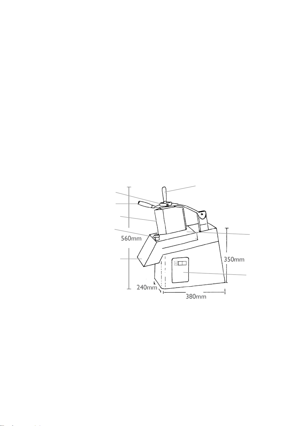
Metcalfe CJ24 Installation and operation manual

1
METCALFE CJ24 VEGETABLE PREPARATION MACHINE
Operating & Maintenance Instructions

2
Introduction
The special tools or devices supplied with the machine are designed and supplied in
accordance with legal requirements and safety standards.
Dimensional drawings and photographs are supplied as examples and as a point of reference to
facilitate comprehension of the texts.
As a consequence of its continual efforts to develop, update and improve its products, the
Manufacturer reserves the right to modify any of the dimensional, structural or aesthetic
characteristics of the machine and its accessories and to make variations in technical features
or the design of any primary component or device.
Moreover, the Manufacturer reserves the right to suspend production and supply of the
machine, spare parts and accessories, shall be free of any liability with respect to such action
and is under no obligation to issue prior warning to any person or organization.
Technical characteristics, dimensions, performance, supplied equipment and other
data quoted in this document are given as examples only. This data is not binding and
may vary without prior notice.
Figure 1
A
B
C
D
E
F
G
A - Lock
B - Large oval inlet for
insertion of vegetables
C - Presser handle
D - Pestle for small inlet
E - Handle of pestle
F - Disk protection guard
G - Control panel
H - Outlet
H

3
GENERAL INDEX
SECTION 1 - GENERAL INFORMATION
1.1 Technical information
1.2 Uses of the machine
1.3 Equipment and special accessories
1.4 Safety devices
1.5 Electric wiring
1.6 Warnings and instructions regarding safety
1.7 Noise levels
SECTION 2 - INSTALLING THE MACHINE
2.1 Characteristics of the site of installation
2.2 Electric power required
2.3 Conditions required for safety, protection of the operator and risk prevention
SECTION 3 - PREPARING THE MACHINE FOR OPERATION
3.1 Unpacking the machine
3.2 Setting up for operation
3.3 Installing dismantled parts
3.4 Connections
SECTION 4 - USING THE MACHINE
4.1 Description of the controls
4.2 Starting the machine
4.3 Cleaning the machine
SECTION 5 - GENERAL MAINTENANCE
5.1 Maintenance
5.2 Trouble-shooting
5.3 Storing the machine - what to do if the machine is not used for long periods
5.4 Instructions for specialised installation operators
APPENDICES:
Exploded view of the machine and replaceable parts
Warranty certificate
Electrical PAT certificate

4
SECTION 1 - GENERAL INFORMATION
These instructions relate to the Metcalfe CJ24 Vegetable Preparation Machine - A machine
designed for cutting vegetables of all kinds.
The identification plate is attached at the rear of the machine on the left- hand side, close to the
outlet of the power cable. The data indicated in the identification plate are as follows:
1.1 Technical information
Average production capacity about 200 kg/hr
Operation voltage 240-415V AC - 50 Hz
Installed power: single-phase 240V 50Hz 0.55kW (0.75HP) 3.5A
Installed power: three-phase 230 240V 50Hz 0.55kW (0.75HP) 1.8A
Installed power: three-phase 400 415V 50Hz 0.55kW (0.75HP) 1.0A
Net weight 20 kg
Average noise level 58 dB (A)
Overall dimensions (length/depth/height) 23.5 cm x 51 cm x 48.5 cm
Dimensions of packing (length/depth/height) 32 cm x 60 cm x 55 cm
Overall weight 22 kg
1.2 Uses of the machine
This machine is a high-performance vegetable cutter suitable for cutting fresh vegetables of all
known types, e.g. carrots, celery, potatoes, peppers, courgettes, tomatoes and other types of
similar density.
1.3 Equipment and special accessories
The basic model of the machine includes the supply of the following devices and materials:
1 low-ridge expulsion disc - no. 6 in exploded view
1 vegetable presser (pestle) - no. 33 in exploded view
1 copy of the instructions and maintenance manual
For available accessories, description of operation and uses of the machine please see
pages 5 and 6 of this manual.

5
Table 1

6
VARIOUS COMBINATIONS OF DISCS AND TYPES OF OPERATIONS
Type of Cut
Rotating Disc
Fixed Disc
Expulsion Disc
Slices
1mm
2mm
3mm
4mm
5mm
6mm
8mm
10mm
1mm delicate
2mm delicate
E 1
E 2
E 3
E 4
E 5
E 6
E 8
E 10
S 1
S 2
No
No
No
No
No
No
No
No
No
No
Low
Low
Low
Low
Low
Low
Low
Low
Low
Low
Curved strips
2.5 x 2.5mm
4 x 4mm
6 x 6mm
8 x 8mm
10 x 10mm
H 2.5
H 4
H 6
H 8
H 10
No
No
No
No
No
Low
Low
Low
Low
Low
Strips
6 x 6mm
8 x 8mm
10 x 10mm
E 6
E 8
E 10
B 6
B 8
B 10
Low
Low
Low
Cubes
8 x 8 x 8mm
10 x 10 x 10mm
12 x 12 x 12mm
20 x 20 x 20mm
E 8
E 10
E 10
E 14
D 8 x 8
D 10 x 10
D 12 x 12
D 20 x 20
High
High
High
High
WARNING:
Do not use any other combination of rotating and fixed
discs other than those stated above as this will damage
the machine and invalidate your warranty.
Grating
V
No
High
Short thin strips/julienne
2 mm
3 mm
4 mm
7 mm
Z 2
Z 3
Z 4
Z 7
No
No
No
No
High
High
High
High
Table 2

7
Slicing discs
Slicing discs
Stick cutting discs Stick cutting discs
E2 E3 E4 E5 E6 E8 E10 E14
S1 S2 E1 X1-8
Slicing disc with an adjustable thickness
from 1 to 8 mm. All stainless steel.
H4 H6 H8 H10

8
Shredding-gratin discs Cube cutting discs
Disc holding rack
1.4 Safety devices
Like all our products, this machine was designed and manufactured to offer a high degree of
safety during use together with high levels of performance, easy operation and a high degree of
reliability. All safety devices are incorporated in the basic construction of the machine to ensure
a high level of reliability and to eliminate the possibility of manipulation.
As a safety measure, the machine is equipped with micro switches, which switch off the power
supply if the cover (F - Fig.1) is not positioned correctly and if the presser (C -Fig.1) is not
lowered completely. These devices are of the active safety type with forced opening of contacts
(IEC 337-1A) and are used to protect the operator's hands so that even with a voluntary
movement the moving cutting blades cannot be reached.
The start and stop controls switch the machine on or off through a command interface equipped
with a low-voltage (24V), safety, insulation transformer (CEI 14-6), which feeds an electro-
magnetic contactor that starts the machine by switching on the power circuit.
This type of circuitry impedes spontaneous starting after every interruption or variation of the
power supply voltage, making it necessary to have voluntary start commands (resetting) so as
Z2 Z3 Z4 Z7 V
E8 E10 E12 E14
D8x8 D10x10 D12x12 D20x20

9
to prevent any dangerous situation caused by spontaneous re-starting when mains voltage is
supplied to the machine. The controls are protected against accidental use:
Thermal protection of the motor.
Protection by means of a fuse in the low-voltage auxiliary circuit.
The electric system is designed in conformity with European regulations CEI EN 60204-1 (CEI
44-5 § 44-6 sections 2119 E & 1364) - The safety devices of the mechanical type, which are
incorporated in the main structure of the machine to provide it with a high degree of intrinsic
safety and controllable manipulation, are those listed below:
Large oval inlet (B Fig.1): for insertion of vegetables.
Large oval inlet shutter and vegetable presser (C Fig.1): impedes introduction of hands or
fingers through the inlet when the machine is in operation.
Small circular inlet (diameter 56 mm)(D Fig.1): for insertion of vegetables. The small
diameter and considerable depth prevent the hands and fingers from being introduced
through the inlet.
Outlet (H Fig.1) for cut/sliced vegetables: the particular form of this opening does not allow
the hands or fingers to reach the moving parts inside the machine.
The safety measures and devices mentioned above conform to prescribed standards in
European regulations EEC 89/392 - 94/44 - 93/68.
1.5Electric wiring
The electric wiring of the machine is designed according to the technical regulations in CEI EN
60204-1 CEI 44-6 section 1364, which refer to electrical parts and equipment in industrial
machinery cf. Part 2 - Designation of the components and examples of drawings, diagrams,
tables etc.
1.6Warnings and instructions regarding safety
Please read the following warnings very carefully. Anyone who uses this machine must have
read and be fully aware of their content.
WARNINGS ALONE WILL NOT ELIMINATE THE RISK OF DANGER....
Remember that instructions or warnings cannot replace industrial safety regulations and really
act as a back-up measure, reminding operators to respect the regulations, which must be
observed at all times.
FAILURE TO OBSERVE ANY INSTRUCTIONS AND SAFETY REGULATIONS AND
IMPROPER USE OF MACHINE MAY LEAD TO INJURY OF THE OPERATOR.
1. This machine, which features a design based on very modern conceptions, was constructed
to offer high levels of performance together with maximum safety for the operator.

10
2. Before starting the machine the operator must read this instruction manual completely and
be fully aware of its contents.
3. Connection and preparation for operation must be carried out only by a specialised
installation expert, who must use the appropriate instruments to take the preliminary step of
verifying the effectiveness of the ground circuit the machine is to be connected to.
The person responsible for installation must also check the validity of the earth connection
of the machine and subsequently execute connection to the mains circuit according to the
manner prescribed in the current regulations of the country in which the machine is used.
4. The machine must be used only by qualified personnel, who must have reached the
minimum age prescribed by law for the work involved in its use and a general acceptable
level of manual skill for coordination of movements required in correct use, fully respecting
the safety regulations and precautionary measures taken to avoid accidents or damage to
persons or things.
The user must under no circumstances attempt to perform repair work on this machine and
must never remove any component part. In the case of breakdown or damage, the user
must contact an assistance service specialised in the repair of this kind of machine.
5. Do not introduce hands, fingers or any object or tool into the machine close to rotating or
moving parts or any mobile component.
6. To remove (from the inlet or outlet openings) any residual substances from the machine
after it has been used stop the machine, in the safe condition, using the control START/
STOP/0 and proceed as required, using a suitable wooden instrument such as a spoon or
spatula to remove the residue remaining inside.
7. During operation of the machine it is absolutely forbidden to raise or remove the cover,
upturn or tilt the machine or open or remove the safety housing located at the bottom. This
kind of action or improper handling can seriously damage the machine itself, whatever
product is being processed inside it and also the operator or other persons.
8. Before starting work button up tightly and securely the cuffs of your overalls or shirt.
Remove scarves, ties or any other loose garment that may become entangled in any part of
the machinery.
If you have long hair, use pins, a net or any other accessory to keep it in place.
Remove rings, your watch, bracelets and any other item.
Use footwear suitable for the workplace, as prescribed and recommended by safety
regulations in every country in the world.
9. Cleanliness of the area surrounding the machine is a further and very important safety
factor. It is necessary to always keep clean and dry the machine, the work top and the floor
surface around the machine, using appropriate methods to remove any dust, fragments of
foodstuffs, residual substances etc.
A wet floor surface, fragments of products or other residual substances can make the floor
slippery, thus generating risky and dangerous conditions. Proper lighting is also a safety
factor and is important for the operator in particular.
10. When cleaning the machine or replacing discs, use soft but strong five-finger gloves for
protection. The gloves should not drastically reduce sensibility and should allow for firm
control over any objects handled.
11. Always remember that whenever any machine is used, certain risks may continue to be
present. Always bear this mind! Before starting any work concentrate your attention on
the operation you are about to start performing.
Be careful at all times and look out constantly for danger, keeping your wits about you to
ensure you do not run any risks. This is of fundamental importance for the operator.
If the operator is subject to any difficult physical condition or may for any reason whatsoever
have dulled reflexes or suffer (also temporarily) from even the slightest form of malaise that
may cause reduced vigilance, he or she must not use the machine.
12. All protective and safety devices (whether electric or mechanical) installed in the machine
must be kept in perfect working order at all times. The warning stickers and other

11
indications attached to the machine must never be removed and always kept visible and
legible.
13. Never use the machine if you are under the influence of alcohol, have taken psychotropic
drugs or any other substance or medicine that may alter the normal state of vigilance.
14. Before starting work always make sure the products you are going to introduce in the
machine are suitable with respect to their type, quality and size.
15. Do not wash and/or clean by spraying water onto the machine and do not place it in water
or any other liquid to avoid the risk of electrocution and other serious damage.
16. Do not place any heavy weight or object on the surface of the machine and do not stand or
climb onto it for any reason.
17. Any operator must be of the minimum age prescribed by law and must have received (from
another experienced operator at least) the appropriate technical training regarding the
machine before being allowed to use it.
18. Before performing cleaning operations, maintenance or moving the machine, remove the
electric connection plug from the mains socket.
If the power socket is of the EEC European type, first turn the selector with interlocking
device to the "0" (zero)(off) position and then remove the plug.
19. Periodically check that the power cable is in perfect condition, without any abrasion, cracks
or swelling and that it is not tangled or twisted. If any alteration is found, replace it
immediately. Never try to move or raise the machine by pulling on the cable or using it as a
hoist.
Never attempt to remove the plug from the socket by pulling on the power cable. Protect
the cable against high temperature, contact with oil and sharp edges.
20. The machine must not be used in the open without adequate and effective protection
against the rain or liquids sprayed from any direction. Keep the machine away from any
source of heat.
Never place on or inside the machine any cutting disc or other instruments or accessories.
Do not use the machine close to flammable liquids or gas.
21. Do not allow children to tamper or touch the machine.
22. Do not use the machine for any use (albeit similar) other than that prescribed. Do not
attempt to alter or modify in any way any component of the machine.
1.7 Noise levels
Average values recorded at the main place of operation according to DIN 45635/a.
Noise level while switched on: 53 dB(A)
Noise level during operation: 65 dB(A)
SECTION 2 - INSTALLING THE MACHINE
2.1 Characteristics of the site of installation
The machine does not require any form of anchoring to the work top or floor. Set the machine
in the most appropriate manner at the chosen site of operation. Bear in mind when selecting
the location the dimensions of the machine itself and the type of products to be processed,
leaving sufficient space for the operator or one person to move freely around the machine.
All the support feet located under the base must rest on a solid, stable, uniform and properly-
levelled surface.
Install close to the machine and in the most convenient position a shunt connection box or
terminal board for distribution of mains power fitted with a suitable socket with current switch/
limiter and, preferably, also fitted with a high-sensibility thermo-magnetic ground-fault circuit-
interrupter.

12
The installation site must be properly illuminated to facilitate working with the machine. You
should avoid setting up the machine in places that are too dark or where bright or excessive
light is likely to disturb you.
Make sure that nothing can fall onto the machine or cause an obstruction over the ventilation
slits. This would cause overheating with consequent risks and danger for the operator and
would probably damage the machine itself.
For the particular type of operation the machine has to perform there must be low levels of dust
in the surrounding environment. The level should not exceed 0.03 g/cu.m (0.0012 oz/cu.m).
Ambient temperature must not exceed the following limits in the conditions given:
Temperature for normal operation:
Minimum 0°C. Max + 35°C. (Minimum 32°F. Max + 95°F)
Temperature for storage:
Minimum -15°C. Max + 65°C. (Minimum -6.8°F. Max +149°F)
Relative humidity: Max 80% with ambient temperature of 20°C (68°F)
Relative humidity: Max 50% with temp. from 20°C to 60°C (68°F to 140° F)
Altitude of site of installation: Max 1,000 m (305 ft) a.s.l.
For installation above 1,000 m special electrical equipment has to be installed.
2.2 Electric power required
Install the terminal board for mains distribution close to the machine without having to use
running extension leads, which are strictly forbidden.
The power cable output coupling is located at the rear of the machine and has a section
diameter suitable for the installed power.
The maximum supply voltage variation permitted must be lower than 5% with respect to the
maximum rated value of 400V. See the electric diagram. Electrical connection of the machine to
the mains circuit must be carried only by a qualified (civil or industrial) installation technician
with specific experience or recognized specialist, respecting all current technical and safety
regulations of the country where the machine is used.
2.3 Conditions required for safety, protection of the operator and risk prevention
With regard to safety, apart from the conditions recommended by various authorities that
preside over this particular area of industrial interest and any regulations laid down by the
managerial department of the firm/ organization in which the machine is used, we should like to
draw the attention of safety controllers and operators to the following instructions and warnings:
Always wear suitable clothing when working with this machine.
While the machine is operating, never bring your hands close to any moving parts or other
mobile parts, whether totally or partially accessible, and do not introduce hand or fingers
through any slit or inlet or outlet opening in the machine.
Do not perform any operation which is not expressly indicated in the descriptions of the
operative cycles of the machine.
Always keep the work place and area surrounding the machine clean and free from any
inconvenient obstacles, using a rational approach to position the products to be processed,
finished products and tools or accessories.
Do not tamper with and do not alter the mechanisms or degree of effectiveness of safety
devices installed in the machine and, in particular, do not alter or tamper with the cover
attachments, micro switches or any other device or component in the electric circuit.
Any alteration, modification or tampering with components of the machine is in fact
fraudulent action and involves the assumption by the party that performs such action of all
civil and penal liability with regard to any possible damage to persons and/or things that may
derive from such action.

13
SECTION 3 - PREPARING THE MACHINE FOR OPERATION
3.1 Unpacking the machine
The machine is packed in a strong carton box. Open this box from the upper side, as indicated
by the arrow, remove the anti-impact materials and raise the machine, holding it with both
hands at the bottom. Free the machine from the protective nylon wrapping and perform
preliminary cleaning of the external surface of the machine, using a soft dry cloth.
3.2 Setting up for operation
Transfer the machine to the place where it is required for operation, bearing in mind its size and
the dimensions of the containers for the products to be processed and for finished products,
leaving a sufficient space all around the machine for movement.
The base must rest on a solid, uniform and properly levelled surface. The machine requires no
anchoring to the supporting surface.
3.3 Installing dismantled parts
To facilitate packing and transportation, certain components of the machine are supplied
dismantled. However, tests are carried out at the factory before shipment to verify that they
function correctly when installed. To install these components, proceed as follows:
Take hold of the presser lever and pull upwards (C Fig.1)
Rotate the knob (A Fig.1) by a half- turn until a click is heard and the released knob itself
partially moves out.
With both hands take hold of and raise the cover (F Fig.1)
On the rotating hub, install first of all an expulsion disc (high-ridge or low-ridge according to
requirements refer to table 2), making sure that the drive pins on the hub are properly
inserted in the holes in the disc.
NOTE: The expulsion disc MUST ALWAYS BE INSTALLED so that the discs can operate
in the correct position.
If you have to carry out operations that require only one disc, insert only one rotating disc above
the expulsion disc. If you have to carry out operations that require the simultaneous use of two
discs (Table 1), insert the following devices in the order given below:
1° - Expulsion disc (high-ridge or low-ridge)
2° - Fixed grid
3° - Rotating disc
FOR OPTIMUM USE OF ALL TYPES OF ROTATING DISCS AND, IF REQUIRED,
SIMULTANEOUS USE OF DISCS WITH FIXED GRIDS REFER TO TABLE 1, WHERE ALL
POSSIBLE FUNCTIONAL COMBINATIONS ARE INDICATED.
3.4 Connections
Sections 1.1 and 2.1 describe the fundamental operations for installation and the values of
absorbed power. Connection of the machine to the mains circuit must be carried out by a
specialised installation operator, who must have all the technical instruments required for this
purpose.

14
To determine the parameters for the section switch with interlocking device and the thermo-
magnetic ground-fault circuit interrupter refer to CEI –IEC and technical regulations in force in
the country where the machine is installed.
The connection plug must be connected to an interlocked socket, capable of providing the
characteristics indicated in section 1.1 of this manual.
Machines with three-phase power supply must be connected to a safety socket, according to
the cyclical sequence of the phases indicated on the label, located close to the end of the power
cable of the machine.
The cyclical sequence of phases of the socket inside the distribution box must be attached with
the sequence indicated on the plate attached to the cable.
The exact combination of the cyclical sequence of phases of the machine with that of the mains
circuit ensures the correct direction of rotation of the motor and avoids the necessity to repeat
connection operations of the plug and excludes any risk of serious damage which may result
from an erroneous connection.
Carry out electrical connection, using the methods described and also using a sequence-meter.
N.B. The earth cable (yellow/green) must be connected to the specific pin marked with the
earth-connection symbol and codes PE as per CEI/IEC standards.
Connection of the power cable to the switch must be carried out, respecting the wiring
configuration indicated in the diagram attached to the power cable itself. The same diagram is
indicated below:
Figure 2
Single-phase Three-phase
L
L1
L2
L3
N

15
SECTION 4 - USING THE MACHINE
4.1 Description of the controls (Fig.3)
The control panel is located on the right side of the machine and has the following switches:
A - Push-button for STOP (OFF). When this button is pressed, the motor will stop.
B - Push-button for START (ON). When this button is pressed, the machine starts and will
continue to run.
Figure 3
4.2 Starting the machine
Install the discs required for the operation to be performed by the machine, making sure the
combinations are correct by consulting table 1.
1 - Press the start control (A Fig.3)
2 - Take hold of the presser lever (C Fig.1), raise it and keep in the raised position.
3 - Introduce the vegetables to be processed (transformed) through the large oval inlet (B
Fig.1).
4 - Gradually lower the presser lever, exercising light pressure so as to obtain the best results
without subjecting the transmission mechanism to any anomalous stress. When the presser
lever reaches the limit of the distance it can travel through, raise it and repeat the operations
described above from point 2, proceeding until the work cycle has been completed.
To obtain round slices, when cutting vegetables of an almost cylindrical shape such as carrots,
cucumbers, courgettes etc, feed the vegetables into the small circular inlet and then use the
presser (pestle device) (D Fig.1), pressing down with moderate force. Repeat the cycle as
described until the work is completed.
4.3 Cleaning the machine
N.B. Before starting to clean the machine, turn the machine power switch to the 0
(ZERO) position and pull the plug out gently, making sure you do not pull on the power
feed cable.
Wear protective, five-finger gloves to protect your fingers from cuts caused by manipulation of
the sharp cutting discs. Lock the knob (A Fig.1) and remove the disc-protection cover (F Fig.1).
Carefully take hold of the discs in the machine and wash them thoroughly by immersing them in
warm water. Use a vegetable brush to complete the cleaning process. Do not allow the discs
to touch each other as this can cause damage to the blades.
Using a sponge soaked with a small dose of domestic detergent (with components for hygiene
protection), clean all of the working parts of the machine, repeating the operation if necessary
until a satisfactory result has been obtained.
Remove any residual detergent, using a perfectly clean, slightly damp cloth/ sponge, which
should be rinsed frequently in warm running water.
B
A

16
Do not use abrasive detergents or products/creams for removing calcareous deposits. Do not
use solvents or diluents. Residual traces of these products can contaminate the foodstuffs
introduced into the machine. Do not use synthetic abrasives or metal wool, which might damage
the machine surfaces besides producing unsightly marks and scratching.
SECTION 5 - GENERAL MAINTENANCE
5.1 Maintenance
The machine is constructed very carefully and is fitted with high-quality components such as the
permanently lubricated roller bearings used in the transmission mechanism and motor and a
special transmission belt. These features will help to ensure excellent performance of the
machine with the guarantee of an operative life expectancy unequalled by any similar product.
Therefore, no maintenance procedure, lubrication or periodic adjustment must be carried out on
the machine.
5.2 Trouble-shooting
If you press the start button (A Fig.3) or 'pulse-operation' start button (B Fig.3) and the machine
does not run, proceed as follows:
1. Make sure that voltage is supplied to the mains circuit and see whether the socket switch is
turned to the ON (I) position.
2. Make sure the thermo-magnetic protector and the circuit interrupter have not been triggered
and that the controls are in the correct position.
3. Perform a simple test on both these devices by pressing the respective push-buttons.
4. Press the start button again on the machine.
If the machine still does not run, a maintenance technician must be consulted. The technician
will have to test the above devices again and check the condition of the fuse used to protect the
auxiliary circuit of the machine. The fuse is on the interface card installed inside the machine. If
you see the machine is not working properly, switch it off immediately and isolate it from the
mains circuit by pulling out the plug from the mains socket. Consult the authorised dealer, a
specialised technician or contact the manufacturer directly. The user must not tamper with the
machine.
Metcalfe Catering Equipment Ltd declines all responsibility, both present and future, with regard
to damage to persons or the environment which may derive from tampering with the machine
and in particular with the safety systems and devices by the user or by persons not expressly
authorised by us.
5.3 Storing the machine - What to do if the machine is not used for long periods
If the machine has to be left unused for long periods of time, it must be cleaned thoroughly.
Protect it from dust with a clean dry cloth. Do not cover the machine with plastic bags or sheets
of synthetic material as mould and condensation may develop under them.
5.4 Instructions for specialised installation operators
Detailed instructions regarding connection of the machine are given in other sections in this
manual.
The data indicated below is for specialised technicians, who may have to make a modification in
the original electric connection to vary the operation voltage from 415V to 240V and vice versa.

17
If the voltage has to be changed from 415V three-phase to 240V three-phase (Fig.4), proceed
as follows:
1. The 415V 50Hz three-phase motor has two groups of cables each containing three leads of
three different colours.
2. The three wires with different colours are short-circuited and separated under a cover or
terminal.
3. The other three leads are directly connected to the interface card.
4. To make the connection for 240V three-phase, separate the three leads that are joined.
5. Combine three pairs of leads of the same colour and then recreate the connection of the
leads matched in this way to the terminals of the card marked with the codes U -V -W.
6. Finally, make the new connection of the lead in the bridge position between references 0-
415, moving one end to coincide with the new value (240).
After completing the connections run a test and check for correct direction of rotation of the
motor.
Figure 4
Parts List
(See diagram on next page)
Part
Number
Description
Part
Number
Description
1
Plastic Hopper
21
Nuts for Cable Gland
2
Locking Knob
22
Power Cable
3
Pin Steel Thread for Closure
23
Screw for block for pusher arm
4
Hopper Stainless Steel
24
Block for Pusher Arm
5
Magnet for Hopper
25
Safe Switch Housing Cover
6
Disk Ejector
26
Bracket for Microswitch
7
Shaft Stainless Steel
27
Microswitch
8
Seal for Shaft
28
Cam
9
Bearing
29
Plastic Handle Press
10
Aluminium Head
30
Cap for Cam
11
Flat Washer
31
Pin for Pusher Arm
12
Motor Bracket
32
Pusher Arm
13
Pulley
33
Plunger
14
Holding Motor Screw
34
Screw to secure Handle Press (29)
15
Belt Grip
35
Hopper Complete Stainless Steel
16
Motor
36
Magnetic Sensor
17
Body Stainless Steel
37
Locking Bush
18
Bottom Plate
38
Start Button
19
Rubber Foot
39
Stop Button
20
Single Phase Unit

18
CJ24 Breakdown Drawing
Exploded view of the machine and replaceable parts

19
METCALFE WARRANTY
All Metcalfe products are guaranteed against defects in material and workmanship for a period
of one year from date of Invoice, except where specially noted.
The Company's obligation under this warranty is limited to repairing or replacing, without
charge, any part or parts found to be defective under normal use, in accordance to the specified
operations manual and capacity ratings.
On all return to factory warranty items, it is the responsibility of the purchaser to return the entire
unit to the factory, properly packed and labelled.
All repairs, alterations or replacement of materials or parts not authorised by Metcalfe will
automatically void all warranties in their entirety.
There is a limited 6-month warranty on the following:
Mixer attachments (beater, whisk and dough hook)
Parts purchased or supplied for the repair of Metcalfe equipment
This warranty does not cover the following:
Failure due to neglect, abuse, careless handling or misuse of machine
Failure caused due to improper maintenance
Blender clutches
Knives and gears on can openers
Sharpening of slicer blades
Metcalfe and its suppliers reserve the right to make changes in design and
specification to any product without prior notification.

20
Electrical PAT Certificate
Test Detail
Results
Test Detail
Results
Item:
Item:
Class:
Class 1 / Class 2
Class:
Class 1 / Class 2
Date:
/ /
Date:
/ /
Appliance ID:
Appliance ID:
User ID:
M.C.E.
User ID:
M.C.E.
Visual:
Visual:
Earth Current:
amps
Earth Current:
amps
Class 1 Earth Result/RPE:
Ω
Class 1 Earth Result/RPE:
Ω
RISO:
MΩ
RISO:
MΩ
1 EA:
MA
1 EA:
MA
Class 2 RISO:
MΩ
Class 2 RISO:
MΩ
1 EA:
MA
1 EA:
MA
Insulation (500V):
MΩ
Insulation (500V):
MΩ
Load:
KVA
Load:
KVA
Leakage:
MA
Leakage:
MA
Polarity (leads only):
Table of contents
Other Metcalfe Commercial Food Equipment manuals
Popular Commercial Food Equipment manuals by other brands

LKK
LKK LKK-1BSP user manual

Aqua Computer
Aqua Computer cuplex kryos NEXT RGBpx Operating and assembly manual

Prince Castle
Prince Castle CTS Operation manual

Structural Concepts
Structural Concepts K Series Installation & operating manual

Hussmann
Hussmann Insight Installation & operation manual

lamber
lamber LP6/L-dy instruction manual