Hobbico Tactic TTX660 User manual

TTX660
TM
Tactic’s TTX660 computer transmitter uses
the advanced 2.4GHz spread spectrum
SLT “Secure Link Technology” protocol for
solid, interference-free control of R/C
models. Ball-bearing gimbals, a wireless
trainer system, 30 model memories, and
advanced programming options are just
a few of the benets which can be used
on models of all sizes. Tactic 2.4GHz
transmitters are compatible only with
Tactic brand receivers and those utiliz-
ing the SLT protocol.
2.4GHz 6-CHANNEL
COMPUTER RADIO
INSTRUCTION MANUAL
For safe operation and
best results, it’s
strongly recommended
to read this manual in
its entirety before use! Also read
and understand the instructions
included with the model. Damage
resulting from misuse or
modication will void your warranty.
™
Tactic’
c’
t
he
a
S
LT “
s
olid
mo
d
t
ra
in
adv
a
fe
o
n
t
ra
n
Ta
c
i
n
g
i
ts e
n
a
n
d
u
inclu
d
resu
l
t
i
m
o
dic

2
SLT TECHNOLOGY, Tx-R, AND COMPATIBLE RECEIVERS . . . . . . . . . . . . . . . . . . . .5
RECEIVER INSTALLATION . . . . . . . . . . . . . . . . . . . . . . . . . . . . . . . . . . . . . . . . . . . . . .5
TTX660 POWER SYSTEM . . . . . . . . . . . . . . . . . . . . . . . . . . . . . . . . . . . . . . . . . . . . . .5
Input Power . . . . . . . . . . . . . . . . . . . . . . . . . . . . . . . . . . . . . . . . . . . . . . . . . . . . . .5
Charge Jack and Rechargeable Batteries . . . . . . . . . . . . . . . . . . . . . . . . . . . . . . .6
Power LED . . . . . . . . . . . . . . . . . . . . . . . . . . . . . . . . . . . . . . . . . . . . . . . . . . . . . . .6
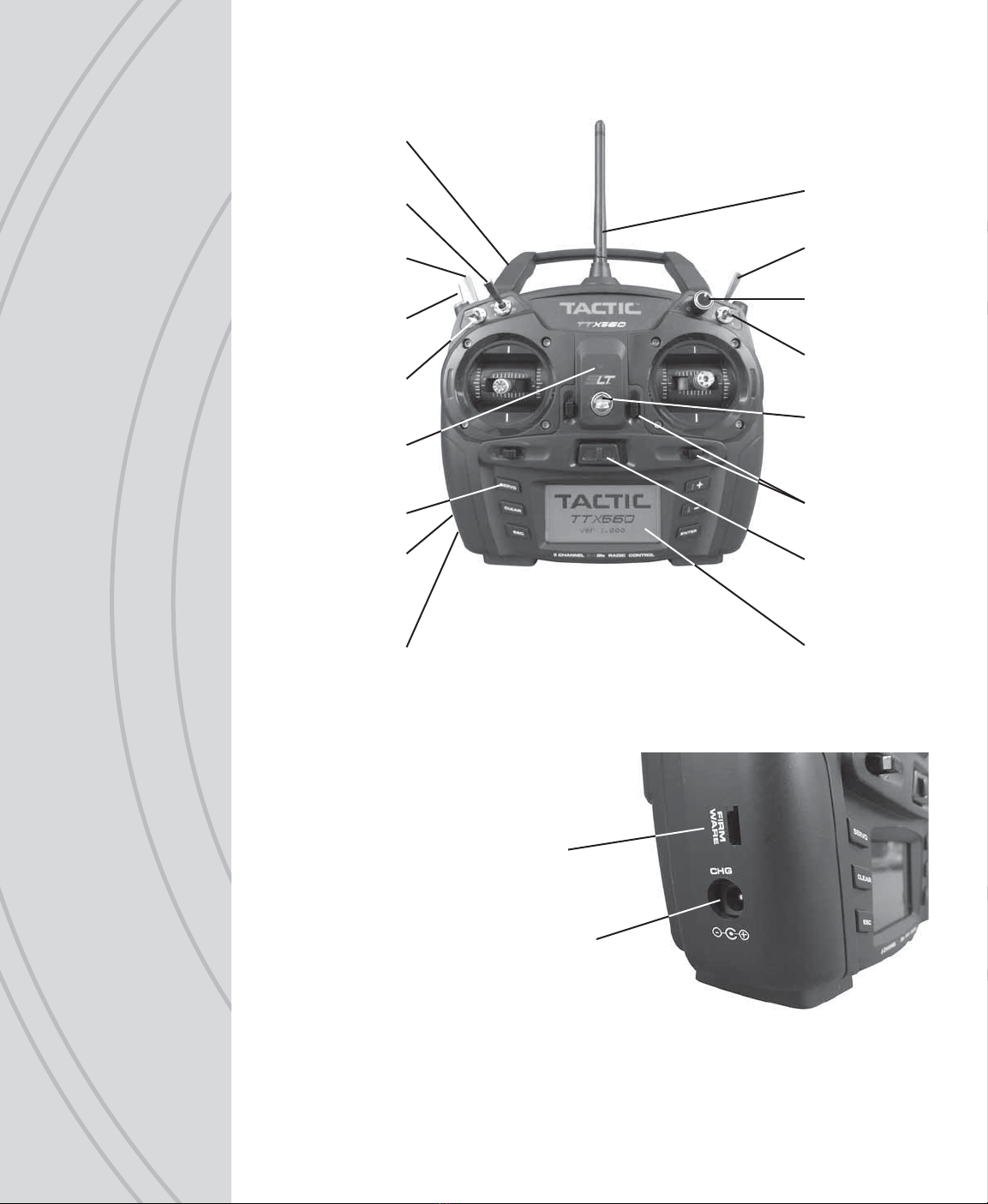
FLIGHT CONTROLS. . . . . . . . . . . . . . . . . . . . . . . . . . . . . . . . . . . . . . . . . . . . . . . . . . .6
Gimbal Sticks. . . . . . . . . . . . . . . . . . . . . . . . . . . . . . . . . . . . . . . . . . . . . . . . . . . . . 7
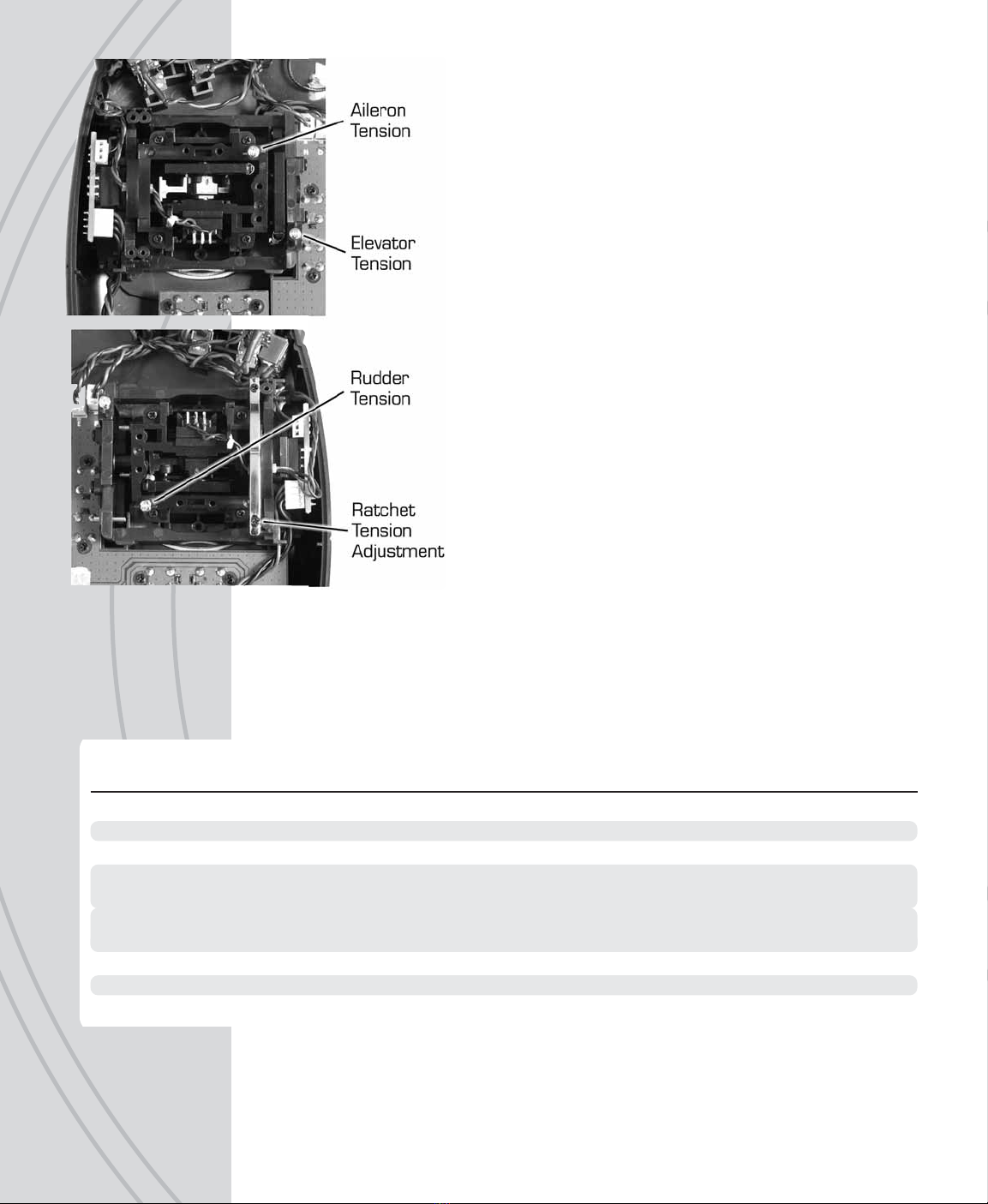
Stick Tension and Throttle Ratchet . . . . . . . . . . . . . . . . . . . . . . . . . . . . . . . . . . . . 7
Case Separation and Assembly. . . . . . . . . . . . . . . . . . . . . . . . . . . . . . . . . . . . . . . 7
Digital Stick Trims . . . . . . . . . . . . . . . . . . . . . . . . . . . . . . . . . . . . . . . . . . . . . . . . .8
Other Controls . . . . . . . . . . . . . . . . . . . . . . . . . . . . . . . . . . . . . . . . . . . . . . . . . . . .8
Antenna . . . . . . . . . . . . . . . . . . . . . . . . . . . . . . . . . . . . . . . . . . . . . . . . . . . . . . . . .8
HOME SCREEN . . . . . . . . . . . . . . . . . . . . . . . . . . . . . . . . . . . . . . . . . . . . . . . . . . . . . .9
MENUS. . . . . . . . . . . . . . . . . . . . . . . . . . . . . . . . . . . . . . . . . . . . . . . . . . . . . . . . . . . . .9
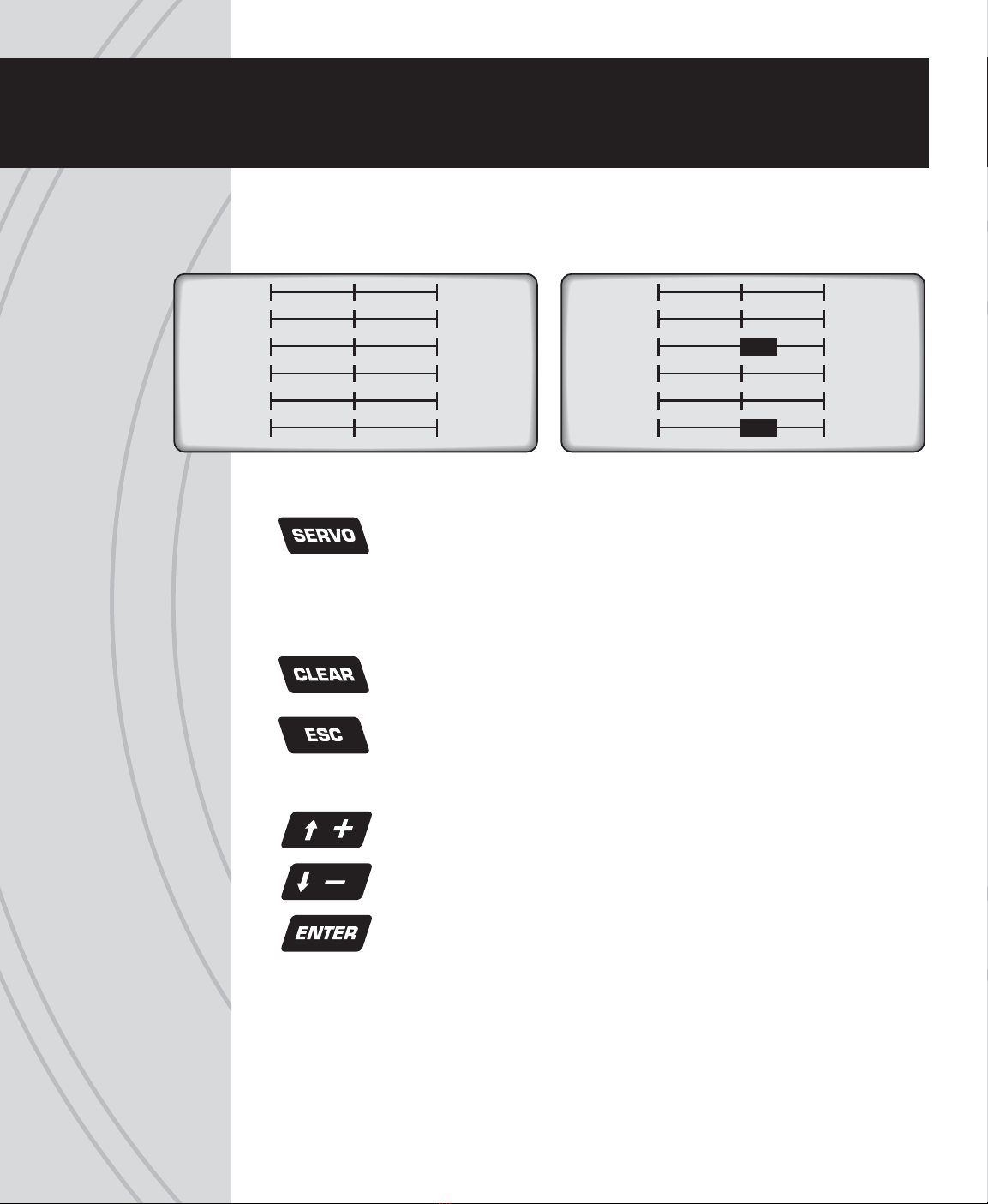
LCD AND PROGRAMMING CONTROLS, MENU NAVIGATION . . . . . . . . . . . . . . . .10
SYSTEM SETUP. . . . . . . . . . . . . . . . . . . . . . . . . . . . . . . . . . . . . . . . . . . . . . . . . . . . . 11
User Name . . . . . . . . . . . . . . . . . . . . . . . . . . . . . . . . . . . . . . . . . . . . . . . . . . . . . . 11
Stick Mode. . . . . . . . . . . . . . . . . . . . . . . . . . . . . . . . . . . . . . . . . . . . . . . . . . . . . . 11
Contrast . . . . . . . . . . . . . . . . . . . . . . . . . . . . . . . . . . . . . . . . . . . . . . . . . . . . . . . . 12
Beep Volume . . . . . . . . . . . . . . . . . . . . . . . . . . . . . . . . . . . . . . . . . . . . . . . . . . . . 12
Battery Alarm . . . . . . . . . . . . . . . . . . . . . . . . . . . . . . . . . . . . . . . . . . . . . . . . . . . .12
LCD Backlight Brightness . . . . . . . . . . . . . . . . . . . . . . . . . . . . . . . . . . . . . . . . . .12
MODEL SETUP MENU – AIRPLANES . . . . . . . . . . . . . . . . . . . . . . . . . . . . . . . . . . . .13
Model Select . . . . . . . . . . . . . . . . . . . . . . . . . . . . . . . . . . . . . . . . . . . . . . . . . . . .13
Model Management. . . . . . . . . . . . . . . . . . . . . . . . . . . . . . . . . . . . . . . . . . . . . . .13
Wing Type . . . . . . . . . . . . . . . . . . . . . . . . . . . . . . . . . . . . . . . . . . . . . . . . . . . . . .15
Flap Settings . . . . . . . . . . . . . . . . . . . . . . . . . . . . . . . . . . . . . . . . . . . . . . . . . . . .15
Tail Settings . . . . . . . . . . . . . . . . . . . . . . . . . . . . . . . . . . . . . . . . . . . . . . . . . . . . .15
Channel Assignments . . . . . . . . . . . . . . . . . . . . . . . . . . . . . . . . . . . . . . . . . . . . . 17
Warnings . . . . . . . . . . . . . . . . . . . . . . . . . . . . . . . . . . . . . . . . . . . . . . . . . . . . . . . 17
Trainer . . . . . . . . . . . . . . . . . . . . . . . . . . . . . . . . . . . . . . . . . . . . . . . . . . . . . . . . .18
Trim Setting . . . . . . . . . . . . . . . . . . . . . . . . . . . . . . . . . . . . . . . . . . . . . . . . . . . . .18
SETTINGS MENU – AIRPLANES . . . . . . . . . . . . . . . . . . . . . . . . . . . . . . . . . . . . . . . .18
Servo Set (reverse, sub-trim, travel limits) . . . . . . . . . . . . . . . . . . . . . . . . . . . . . .18
Dual-Rates and Exponential . . . . . . . . . . . . . . . . . . . . . . . . . . . . . . . . . . . . . . . .19
CH5 and CH6 Set . . . . . . . . . . . . . . . . . . . . . . . . . . . . . . . . . . . . . . . . . . . . . . . .20
Throttle Curve . . . . . . . . . . . . . . . . . . . . . . . . . . . . . . . . . . . . . . . . . . . . . . . . . . . 21
Throttle Cut . . . . . . . . . . . . . . . . . . . . . . . . . . . . . . . . . . . . . . . . . . . . . . . . . . . . . 22
TABLE OF CONTENTS

3
Aileron Differential . . . . . . . . . . . . . . . . . . . . . . . . . . . . . . . . . . . . . . . . . . . . . . . .23
Aileron Mixer . . . . . . . . . . . . . . . . . . . . . . . . . . . . . . . . . . . . . . . . . . . . . . . . . . . . 24
Rudder Mixer . . . . . . . . . . . . . . . . . . . . . . . . . . . . . . . . . . . . . . . . . . . . . . . . . . . .25
Flap Mixer . . . . . . . . . . . . . . . . . . . . . . . . . . . . . . . . . . . . . . . . . . . . . . . . . . . . . .25
Air Brake Set . . . . . . . . . . . . . . . . . . . . . . . . . . . . . . . . . . . . . . . . . . . . . . . . . . . .26
Programmable Mixer . . . . . . . . . . . . . . . . . . . . . . . . . . . . . . . . . . . . . . . . . . . . . . 27
Rf Output . . . . . . . . . . . . . . . . . . . . . . . . . . . . . . . . . . . . . . . . . . . . . . . . . . . . . . .28
Timer . . . . . . . . . . . . . . . . . . . . . . . . . . . . . . . . . . . . . . . . . . . . . . . . . . . . . . . . . .28
MODEL SETUP MENU – HELICOPTERS. . . . . . . . . . . . . . . . . . . . . . . . . . . . . . . . . .29
Swash Type . . . . . . . . . . . . . . . . . . . . . . . . . . . . . . . . . . . . . . . . . . . . . . . . . . . . .29
SETTINGS MENU – HELICOPTERS . . . . . . . . . . . . . . . . . . . . . . . . . . . . . . . . . . . . .30
Servo Set, Dual-Rates, Exponential, RF Output, Timer. . . . . . . . . . . . . . . . . . . .30
Throttle Cut . . . . . . . . . . . . . . . . . . . . . . . . . . . . . . . . . . . . . . . . . . . . . . . . . . . . . 31
Throttle Hold . . . . . . . . . . . . . . . . . . . . . . . . . . . . . . . . . . . . . . . . . . . . . . . . . . . . 31
Throttle Curve . . . . . . . . . . . . . . . . . . . . . . . . . . . . . . . . . . . . . . . . . . . . . . . . . . . 32
Pitch Curve . . . . . . . . . . . . . . . . . . . . . . . . . . . . . . . . . . . . . . . . . . . . . . . . . . . . .33
Gyro Mixing . . . . . . . . . . . . . . . . . . . . . . . . . . . . . . . . . . . . . . . . . . . . . . . . . . . . . 34
Swash Mixing. . . . . . . . . . . . . . . . . . . . . . . . . . . . . . . . . . . . . . . . . . . . . . . . . . . . 34
Throttle Mixing . . . . . . . . . . . . . . . . . . . . . . . . . . . . . . . . . . . . . . . . . . . . . . . . . . .35
Rudder Mixing . . . . . . . . . . . . . . . . . . . . . . . . . . . . . . . . . . . . . . . . . . . . . . . . . . .35
Swash Ring . . . . . . . . . . . . . . . . . . . . . . . . . . . . . . . . . . . . . . . . . . . . . . . . . . . . .35
Programmable Mixer, RF Output and Timer . . . . . . . . . . . . . . . . . . . . . . . . . . . .36
DRONE MENUS . . . . . . . . . . . . . . . . . . . . . . . . . . . . . . . . . . . . . . . . . . . . . . . . . . . . .36
LINK THE RX TO THE TX . . . . . . . . . . . . . . . . . . . . . . . . . . . . . . . . . . . . . . . . . . . . . .36
FAILSAFE FUNCTION . . . . . . . . . . . . . . . . . . . . . . . . . . . . . . . . . . . . . . . . . . . . . . . . 37
FLIGHT SIMULATOR CONNECTION . . . . . . . . . . . . . . . . . . . . . . . . . . . . . . . . . . . . . 37
WIRELESS TRAINER . . . . . . . . . . . . . . . . . . . . . . . . . . . . . . . . . . . . . . . . . . . . . . . . . 37
RANGE TEST . . . . . . . . . . . . . . . . . . . . . . . . . . . . . . . . . . . . . . . . . . . . . . . . . . . . . . .39
WARNING INDICATIONS . . . . . . . . . . . . . . . . . . . . . . . . . . . . . . . . . . . . . . . . . . . . . .40
SYSTEM CHECK AND OPERATION . . . . . . . . . . . . . . . . . . . . . . . . . . . . . . . . . . . . .40
FLYING THE AIRCRAFT . . . . . . . . . . . . . . . . . . . . . . . . . . . . . . . . . . . . . . . . . . . . . . . 41
IMPORTANT WARNINGS AND PRECAUTIONS . . . . . . . . . . . . . . . . . . . . . . . . . . . .42
TTX660 SPECIFICATIONS . . . . . . . . . . . . . . . . . . . . . . . . . . . . . . . . . . . . . . . . . . . . .43
TROUBLESHOOTING. . . . . . . . . . . . . . . . . . . . . . . . . . . . . . . . . . . . . . . . . . . . . . . . .43
SAFETY GUIDE . . . . . . . . . . . . . . . . . . . . . . . . . . . . . . . . . . . . . . . . . . . . . . . . . . . . .44
ACCESSORIES. . . . . . . . . . . . . . . . . . . . . . . . . . . . . . . . . . . . . . . . . . . . . . . . . . . . . .44
FCC STATEMENT. . . . . . . . . . . . . . . . . . . . . . . . . . . . . . . . . . . . . . . . . . . . . . . . . . . .45
EU COMPLIANCE STATEMENT . . . . . . . . . . . . . . . . . . . . . . . . . . . . . . . . . . . . . . . .45
WARRANTY INFORMATION . . . . . . . . . . . . . . . . . . . . . . . . . . . . . . . . . . . . . . . . . . .45

4
Neck Strap
Eyelet
Power
Switch
Antenna
LED Power
Indicator
LCD
Pushbuttons
Carrying
Handle
Switch A
Switch E
Switch F
Switch B
Switch D
Dial
Switch H
Charge Jack
Firmware
Upgrade
Jack
Trim Levers
Charge Jack
Firmware
Upgrade
Jack

5
Tactic’s custom SLT technology ensures that transmitters emit a strong, clear, frequency-
hopping 2.4GHz signal, and that your compatible receiver accepts no signal except
yours. Binding Tactic brand receivers is as simple as pushing
a button, which creates a locked-in, interference free link. The
TTX660 radio can store up to 30 models in memory, making it
perfect to control a full eet of models with the super-affordable
Tactic brand 2.4GHz receivers. The TTX660 is also compatible with non-Tactic brand
receivers which use the *SLT protocol, for the ultimate in convenience and exibility.
*Make sure optional receivers have the genuine SLT protocol before use with the TTX660.
The TTX660 is also compatible with all transmitter-ready
aircraft bearing the “Tx-R” logo. Such aircraft include
receivers having the SLT protocol.
Always mount the optional receiver, servos, switch harness, battery, electronic speed
control, etc. as explained in the manual included with such equipment and/or the model.
Keep the Rx and its antenna(s) as far away from the engine/motor, servos, and ESC and
other electronic items as much as possible. It may also be a good idea to mount the
Rx inside certain models using Velcro,
®and wrap it in foam rubber to prevent damage
from strong vibrations or crash damage (except in extremely warm environments). It’s
best to have as few items surrounding the receiver’s antenna tips as possible inside the
model, to allow for the most obstruction-free signal path to the transmitter. Exposing the
receiver’s antenna tip outside the model is recommended if possible. For receivers with
two antennas, position the antennas at 90 degree angles with the tips resting at least 5
inches apart. If possible, allow one antenna to point vertically above the receiver itself.
INPUT POWER
Four 1.5V “AA” alkaline cells (included) or 1.2V “AA” NiCd or NiMH cells supply power
to the TTX660. Do not mix cell types, or old and new cells, etc. Slide open the battery
door to nd the four “AA” cell battery holder. Insert all cells with the proper polarity as
shown inside the battery holder. Carefully tuck the wires and battery holder inside the
battery compartment so not to damage them when closing the battery door.
Alternatively, an assembled 4.8V NiCd or NiMH “AA” at pack can be installed. Remove
the alkaline cell holder from the battery compartment and carefully observe the polarity
SLT TECHNOLOGY, Tx-R,
AND COMPATIBLE RECEIVERS
™
TM
RECEIVER INSTALLATION
TTX660 POWER SYSTEM

66
of the wires before disconnecting the plug from the Tx. Install the NiCd or NiMH
battery by rst inserting its connector into the jack in the battery compartment.
Battery voltage is shown on the LCD’s home screen for easy monitoring. A “LOW
BATTERY” warning will show when battery power drops to the voltage value shown in
the BATTERY ALARM screen as described on page 12.
WARNING! Never operate an R/C model with weak Tx batteries! Reduced
operational range and/or possible loss of control of the aircraft could
result. Never mix used and new alkaline batteries. Replace weak alkaline
batteries, or re-charge NiCd or NiMH batteries before attempting a ight!
A “Tx Batt.” timer in the TIMER menu described on page 28 can track the total amount
of time the transmitter has been operational.
See the ACCESSORIES section on page 44 for optional batteries and chargers available
at local hobby retailers.
CHARGE JACK AND CHARGING
RECHARGEABLE BATTERIES
The charge jack should only be used for recharging optional NiCd or NiMH
batteries (charger not included). Do not try to recharge alkaline batteries.
Charge adapter leads for Futaba®brand transmitters are compatible, with
the center pin being positive polarity. The Tx power switch must be in the
OFF position to recharge batteries. Do not charge batteries at greater than
1 amp. Cycling of the Tx batteries can be accomplished through this jack. Misuse,
improper charging, or over-charging of rechargeable cells can result in damage to the
cells that could include cell rupture, explosion, or re!!
WARNING! Do not accidentally short circuit the terminals inside the charge
jack, as this can cause permanent damage to the radio’s charge circuitry
and battery and void the warranty.
POWER LED
The blue LED illuminates when the power switch is turned on and ample voltage is
supplied by the battery. This LED will ash if battery voltage drops to the voltage set in
the BATTERY ALARM setting described on page 12.
Channels 1– 6 are fully proportional. Channels 5 and 6 can be controlled by a
non-proportional switch, dial, or slide lever, or mixed to channels 1– 4 for full
proportional control.
Aircraft control is accomplished through various electro-mechanical devices which are
manipulated by the pilot, such as the control sticks, toggle switches, dial, or slide levers.
In addition, the Tx can automatically manipulate the pilot’s control inputs electronically
to alter the control signals before they are delivered to the receiver (e.g. mixing two
TTX660 Charge Jack
FLIGHT CONTROLS

7
channels, applying differential reduction to a channel, etc.). Some electronic functions
can be turned on/off by the pilot during ight such as a timer. Other functions should
only be altered while the model is on the ground, such as changing travel limits or
reversing for a particular channel.
GIMBAL STICKS
Ball-bearing construction allows both sticks to provide the
ultimate in smooth, precise control. Stick length can be adjusted
for optimum feel and control. Each stick consists of a base and
a tip. To adjust, hold the base tightly, then loosen the tip by
turning it counter-clockwise. Adjust the stick tip to the desired
length. Tighten the stick by holding the tip in place and turning
the base counter-clockwise until it’s tight against the tip.
STICK TENSION AND
THROTTLE RATCHET
Each control stick can be adjusted for softer or stiffer movement tension. A ratchet is
also included for the throttle stick which can be adjusted for feel depending on personal
preference. Adjustment of either feature requires removal of the rear of the Tx case as
explained in the CASE SEPARATION AND ASSEMBLY section below.
CASE SEPARATION AND ASSEMBLY
WARNING! Failure to follow these instructions for separating and
re-assembling the Tx case can result in permanent damage to the
transmitter, and void the warranty. Contact Hobby Services if you
do not feel comfortable that you can safely and accurately perform
these steps.
ALWAYS disconnect and remove the batteries from the battery compartment
FIRST. Failure to do so can result in permanent damage to the Tx.
Remove the six screws from the back of the Tx case. Carefully pull the case rear
away from the case front and note exactly how all wires are routed inside the case.
After adjustments are made as described in other sections of this manual, close the
case by rst carefully tucking all cables back inside as when the case was opened.
Align the case rear back onto the case front, making sure that no wires are pinched
between the case parts. Press the case halves together. Insert the screws back
into their positions and carefully tighten them until snug - making sure not to cross
the threads or over-tighten the screws. Re-connect the battery holder’s connector
to the socket inside the Tx. Insert the battery into the compartment, and carefully
tuck the wires inside the cavity so they do not become pinched when the door is
closed. Close the battery door.

8
●Stick Tension: Silver screws on the back of each gimbal are
used to adjust the stick tension, as shown at left. Turn the
screw clockwise to make stick tension more rm. Turn the
screw counter-clockwise to make stick tension more light.
●Throttle Ratchet: A silver ratchet bar is mounted across
the throttle gimbal. For airplane use, a more rm ratchet
feel might be desired for the throttle. In this case, turn the
adjustment screw clockwise. For helicopter use, less of a
ratchet feel might be desired. Turn this adjustment screw
counter-clockwise to achieve the desired feel.
DIGITAL STICK TRIMS
The trim controls for the four main channels are digital. Holding
the trim lever will cause the servo output to move repeatedly.
Trim positions are visible on the LCD’s home screen, and stored
into that respective memory. Changing the model memory will
also cause trim settings to change accordingly.
For aircraft with glow engines, the precise position of the trim
lever is helpful when determining the engine’s preferred idle
point. When the main throttle stick is above 50% full throttle,
it will not be possible to trim the throttle servo – even though
the indicator on the LCD will move.
The amount of servo movement for each increment of a digital
trim can be adjusted as desired, as explained in the TRIM
SETTING section on page 18.
OTHER CONTROLS
Each control can be assigned to control one of a variety of functions as desired and
described throughout this manual. See page 4 for the location of all switches, which are
also marked on the Tx by letter. The factory default switch assignments are as follows:
ANTENNA
The strongest signals are emitted at a 45 degree angle from the sides of the antenna.
Rotate and fold the antenna so that it’s not pointing directly towards the model during
ight. Do not grab the antenna during operation as it may affect radio signal quality.
A 2-position Ch2 Elevator Dual-rate Timer Control
B 2-position (No Setting) Gyro Gain
C Dial (No Setting) (No Setting)
D 2-position Ch1 Aileron Dual-rate Aileron, Elevator, and Rudder
Dual-rates (All)
E 3-position Ch4 Rudder Dual-rate Normal/Idle-up Control
F 2-position, Momentary Trainer Throttle Cut
H 2-position Throttle Cut Throttle Hold
I Slide Lever (No Setting) (No Setting)
J Slide Lever (No Setting) (No Setting)
Switch Type Default Function
Airplane
Default Function
Helicopters

9
The factory default screen and menus will be for airplanes.
See the next section for navigating and changing menus for
model type and other functions.
1. Memory Number 5. Timer
2. Model Name 6. Trim Indicators
3. Battery Voltage 7. Signal Status
4. Model Type
The TTX660 has three types of menus.
The SYSTEM SETUP menu allows for setting basic operational
functions for the radio itself.
Selecting and managing the model memories, conguring
the radio for the structure of the airplane, helicopter, drones,
etc. is done in the MODEL SETUP menu. Most functions
apply for airplanes, helicopters, and drones. Select functions
are available for certain model types only.
Setting various radio functions to control the model is done in the SETTINGS menu.
Some settings apply for airplanes, helicopters, and drones. Select settings are available
for certain model types only.
HOME SCREEN
>NAME
01 5.3V
OOO
RF-ON
123
4
5
6
6
7
MENUS
USER NAME :
STICK MODE:
CONTRAST :
BEEP VOL. :
BATT.ALARM:
TACTIC
MODE2
0
0
4.8v
SYSTEM SETUP
MODEL SELECT
MODEL MANAGEMENT
SWASH TYPE
CHANNEL ASSIGNMENTS
WARNINGS
MODEL SETUP
SERVO SET
DUAL, EXPO
CH5 AND CH6 SET
THROTTLE CURVE
THROTTLE CUT
SETTINGS SERVO SET
DUAL, EXPO
SETTINGS
CH5 AND CH6 SET
THROTTLE CUT
THROTTLE HOLD

10
The LCD contrast and brightness is adjustable for optimum viewing. Six pushbuttons
navigate the menus and settings. Single button pushes will result in a single incremental
adjustment on-screen. Holding a button for a short time will result in slow scrolling of
adjustments; continued holding will result in fast adjustments.
Left side buttons:
Press any time to see the servo position screen shown above. Indicators
for certain channels will change depending on model type, wing type, etc.
Moving any Tx control will graphically be shown on this screen. When
setting / adjusting mixes to determine if the mix is as desired, set the
mix and then view this screen. Move all controls to determine if the mix
moves each respective channel as needed.
Quickly resets certain values and settings back to factory defaults. Press
to backspace in the model and user name screens.
Jumps back to the previous screen, and removes certain pop-up messages
from the screen.
Right side buttons: adjustment of values on-screen
Moves the cursor up, and for increasing highlighted values/settings.
Moves the cursor down, and for decreasing highlighted values/settings.
To select or de-select a setting, or enter a screen. Press briey to access
the SETTINGS menu. Press and hold to access the MODEL SETUP menu.
LCD, PROGRAMMING CONTROLS,
MENU NAVIGATION
10%
AILE
2ELEV
3THRO
4RUDD
5AUX1
6AUX2
0%
0%
0%
0%
0%
10%
20%
3 58%
40%
50%
6 58%
-
-
-
-
AILE
ELEV
THRO
RUDD
GYRO
PITC

11
Fundamental settings for the transmitter are located in this
menu. With the power switch in the OFF position, press and
hold ENTER, turn the power switch ON and wait for the
SYSTEM SETUP screen to show. Move the cursor and press
ENTER to select any setting. Press or to change
settings. Press ENTER to conrm the setting.
USER NAME
Enter your name to identify the
radio. The cursor will be under the
rst character to enter. Press
or to nd the desired character,
then ENTER to conrm. The cursor
will automatically move to the next
character. Selecting or can move the cursor freely. Repeat as necessary for up to
8 characters. Pressing CLEAR will move the cursor back one space and erase the
character in that space. Press ESC when nished.
STICK MODE
The TTX660 is factory set to Mode 2 conguration, but can
be changed to Mode 1 (elevator on left, throttle on right). To
change modes in the programming, move the cursor to the
STICK MODE line, highlight and press ENTER, then press
or . Press ENTER to conrm.
In addition to programming changes, stick mode changes require reversal of the throttle
ratchet and elevator arm/spring. Refer to the CASE SEPARATION AND ASSEMBLY
section on page 7 for opening and safely re-assembling the case after the mechanical
adjustments are made. Failure to do this properly can cause permanent damage to
the radio and void the warranty.
Unscrew the right gimbal assembly by removing the four screws
from the front of the transmitter (make a note of the different length
screws and their locations) and then lift it out of the transmitter case.
It is not necessary to disconnect any of the wires. With the gimbal
in hand, carefully unhook the elevator spring from the elevator arm
using needle-nose pliers (A). Unhook the spring from the lower
spring clip and then slide the spring clip out of the gimbal assembly
(B). Raise the elevator arm to a vertical position and slide it off the
mounting pin (C). Reinstall the right gimbal into the transmitter.
Do not over-tighten the mounting screws! Remove the ratchet
bar from the left gimbal assembly by unscrewing the two mounting screws and install
it onto the right gimbal assembly in the same manner over the ratcheted surface. Use
the adjustment screw to set the ratchet tension to your liking (D).
SYSTEM SETUP
USER NAME :
STICK MODE:
CONTRAST :
BEEP VOL. :
BATT.ALARM:
TACTIC
MODE2
0
0
4.8v
SYSTEM SETUP
ABCDEFGHIJKLMNOP
QRSTUVWXYZabcdefghi
jklmnopqrstuvwxyz01
USER NAME
USER:
LEFT
STICK
Rudder
Mode1: Elevator
Mode2: Throttle
Mode1: Throttle
Mode2: Elevator
Aileron
RIGHT
STICK
NORMAL STICK CONFIGURATIONS

12
Unscrew the left gimbal assembly and lift it out of the transmitter
case. Slide the elevator arm onto the mounting pin in the left gimbal
in the same way you removed it from the right gimbal. NOTE:
As you can see, the two gimbals are identical but installed
in the transmitter 180 degrees opposite each other. Insert the
spring clip you removed from the right gimbal into the slot of the
left gimbal beneath the tensioner screw. Reattach the spring you
removed from the right gimbal onto the left. Reinstall the left gimbal
assembly and tighten the spring tensioner screw to your liking.
Close the transmitter as explained in the CASE SEPARATION AND ASSEMBLY section.
CONTRAST
Adjust the LCD’s contrast level for optimum viewing.
LCD BRIGHTNESS
Adjust the intensity of the display’s blue backlight.
BEEP VOLUME
Adjust the loudness of the radio’s beeper as desired. This volume setting affects all
tones that are emitted from the radio including while making adjustments such as trim
adjustments, programming changes, etc. Beep volume for all alarms is not adjustable.
BATTERY ALARM
An alarm will sound and the display will show “LOW BATTERY” when the Tx battery’s
voltage drops to the level shown in this setting. Do NOT set this value too low, as the
radio could lose power very rapidly as the battery nears full discharge and cause a loss
of control of the model. Land the model immediately once this alarm has sounded!
Battery type
Nickel-Cadmium (NiCd)
or Nickel-Metal
Hydride (NiMH)
4.00V 4.40V 4.00V
Alkaline 4.00V 4.00V 3.60V
Default Recommended Minimum
Once all functions in this menu are set, press ESC to return to the home screen.

13
From the home screen, press and hold ENTER for 2 seconds
to nd the MODEL SETUP menu which is for setting of
fundamental operating parameters as shown here.
MODEL SELECT
Memories are available to store parameters for up to 30 different models. This screen
is for selecting the model to be active. Move the cursor to nd the desired model to
make active, and press ENTER. You will be forced to select a model type (airplane,
drone, heli). The radio will automatically return to the home screen.
Changing the model memory is not possible if the Tx battery
voltage is too low. See the INPUT POWER section on page
5. It’s a good idea to keep a record of all settings for each
memory as a backup in case parameters in a particular
memory are accidentally changed, etc.
MODEL MANAGEMENT
Shows basic information regarding
the model setup in the memory
number shown at top in brackets.
Move the cursor up or down to select
/ change the function to adjust, and
press ENTER to enter the function
screen.
Type: Press or to select the
model type as airplane, helicopter,
or drone. Press ENTER to conrm.
Name: Move the cursor to this line and press ENTER. The method for setting the
model name is the same as for entering the USER NAME as described on page 11. The
maximum number of characters is six. Press ESC when nished.
MODEL SETUP MENU – AIRPLANES
MODEL SELECT
MODEL MANAGEMENT
WING TYPE
CHANNEL ASSIGNMENTS
WARNINGS
MODEL SETUP
02 : Axe100
03 : Extra
04 : Cirrus
05 : Novus
06 : Yak-54
01 : GeeBee
MODEL
SELECT
Mode1 Management[01]
Type: Airplane
Name:
Copy
Reset
Erase
GeeBee
MODEL TYPE
AIRPLANE HELICOPTER

14
Copy: To copy all parameters from one model memory to another, place the cursor over
“Copy” and press ENTER. The “COPY FROM” page will show. Highlight the memory
to copy FROM and press ENTER. Now the “COPY TO” page will show.
Place the cursor over the memory number to copy TO, and press ENTER. The conrmation
screen will show.
To NOT proceed with the copy function as shown on-screen, highlight “NO” and press
ENTER to cancel and return to the main MODEL MANAGEMENT screen.
Otherwise, press to highlight “YES” and press
ENTER. All settings that previously existed in the
receiving memory will be permanently erased.
The display will return to the main MODEL
MANAGEMENT screen. Return to the MODEL
SELECT screen to conrm the copy function
was successful by looking at the memory that
was copied “to”.
Reset: To change the parameters of any single
memory except model type and model name use
this reset function. Enter this screen, move the
cursor over the memory to reset and press ENTER.
Select “NO” to cancel or “YES” to proceed with
the reset, and press ENTER.
Erase: Use the erase function to completely clear
all settings in any single memory to factory default
settings. The method for selecting, cancelling, and
approving this function is the same as for reset.
You will be forced to select a model type before
proceeding (airplane, helicopter, or drone).
02 : Axe100
03 : Extra
04 : Cirrus
05 : Novus
06 : Yak-54
01 : GeeBee
COPY
FROM
COPY
TO
02 : Axe100
03 : Extra
04 : Cirrus
05 : Novus
06 : Yak-54
01 : GeeBee
01 : GeeBee
03 : Extra
CONTINUE? NO YES
02 : Axe100
03 : Extra
04 : Cirrus
05 : Novus
06 : Yak-54
01 : GeeBee
MODEL
RESET
05 : Novus
CONTINUE? NO YES

15
WING TYPE
This is for setting the type of tail and wing conguration for
the model. Depending on the mixes used and setup of the
aircraft, it might be necessary to change the aileron, elevator,
or rudder reversing settings to achieve the proper throw
directions for the model.
FLAP SETTINGS
The “FLAP” setting allows for conguration of the ailerons and/or aps of the airplane.
Move the cursor over “1AI” to select from the following options:
1AI: Use this “1 aileron” setting for normal wing types having one aileron on each
wing, where by utilizing a Y-harness one servo input controls the movements of
both servos simultaneously.
1AI1FL: This “1 aileron + 1 ap” setting is for wings having one servo that controls
the ailerons on both wings, and another servo (or 2 servos on a Y-harness) that
controls the aps on both wings (both servos moving in the same direction). Connect
the aileron servo to Rx channel 1, and the ap servo to channel 5. (Not available
for delta.)
2AI: This “2 ailerons” setting is for airplanes having one aileron servo for each wing.
Connect one aileron servo to Rx channel 1, and the other to channel 6. This setting
allows each aileron servo to function independently of the other.
2AI1FL: This “2 ailerons + 1 ap” setting is for airplanes having two separate aileron
servos, requiring one servo to control each aileron, and also one servo (or 2 servos
on a Y-harness) that will control aps for both wings simultaneously. (Not available
for 2 elev tail settings.)
TAIL SETTINGS
“Normal” is the factory default setting for the “TAIL” type. Move the cursor over “Normal”,
press ENTER then or to select from V-Tail, Delta (elevon), and 2 Elevator options.
Press ENTER to conrm the selection. The charts below can aid in determining the
preferred tail and ap setting for the model.
Normal: One servo each is used
for aileron(s), elevator(s), and
rudder.
1AI
Normal
FLAP
TAIL
Airplane - Normal Tail
1AIL/ 2AIL/
1AIL 1FLAP 2AIL 1FLAP
CH1 AIL AIL AIL AIL
CH2 ELEV ELEV ELEV ELEV
CH3 THRO THRO THRO THRO
CH4 RUDD RUDD RUDD RUDD
CH5 AUX1 FLAP AUX1 FLAP
CH6 AUX2 AUX2 AIL2 AIL2

16
V-tail: Elevator and rudder channels are mixed. Two servos are used in the tail – one
for each control surface, with connections as shown in the graphic above. V-tail mixing
controls the airplane’s “pitch” and “yaw” axis at the same time. If the elevator and
rudder functions appear reversed at the control surfaces, it may be necessary to swap
the channel 2 and channel 4 servo plug positions in the Rx. The travel limits for each
servo can be adjusted independently.
Delta wing (elevon): Elevator and aileron channels are mixed, useful for aircraft such
as ying wings and other models not having a tail. Elevon mixing controls the airplane’s
“pitch” and “roll” axis at the same time. One servo is used for each control surface. Travel
limits for each servo can be adjusted separately. If the elevator and aileron functions
appear reversed at the control surfaces, it may be necessary to swap the channel 1 and
channel 2 servo plug positions at the Rx for the delta wing mix. If the delta wing option
is selected, and the “FLAP” option below is set to 2AI1FL, the elevator channel will mix
100% to the aileron channel.
2-Elevators: Elevator channel 2 and
channel 6 are mixed for aircraft which
have two separate servos moving separate
elevator surfaces. Both elevators move
independently, and are independently
adjustable for travel limits, etc.
Airplane - V-tail
1AIL/ 2AIL/
1AIL 1FLAP 2AIL 1FLAP
CH1 AIL AIL AIL AIL
CH2 V-TAIL1 V-TAIL1 V-TAIL1 V-TAIL1
CH3 THRO THRO THRO THRO
CH4 V-TAIL2 V-TAIL2 V-TAIL2 V-TAIL2
CH5 AUX1 FLAP AUX1 FLAP
CH6 AUX2 AUX2 AIL2 AIL2
Left Rudder
ch2 ch4 ch2 ch4
Right Rudder
ch2 ch4
Up Elevator
Airplane - Delta Wing
2AIL/
2AIL 1FLAP
CH1 ELEVON1 ELEVON1
CH2 ELEVON2 ELEVON2
CH3 THRO THRO
CH4 RUDD RUDD
CH5 AUX1 FLAP
CH6 AUX2 AUX1
Elevator
Function
Aileron
Function
Airplane - 2 Elevators
1AIL/
1AIL 1FLAP 2AIL
CH1 AIL AIL AIL
CH2 ELEV ELEV ELEV
CH3 THRO THRO THRO
CH4 RUDD RUDD RUDD
CH5 AUX1 FLAP AIL2
CH6 ELEV2 ELEV2 ELEV2

17
CHANNEL ASSIGNMENTS
This function allows transmitter channels to be re-assigned to different channels before
being sent to the receiver. This can be useful for models having unusual congurations
or inaccessible receivers.
Some small electric ight models use only elevator, throttle,
and rudder channels (not aileron). Here, it’s often preferred
that the rudder be controlled with the opposite stick (right
stick for Mode 2 congurations). Such channel re-assignment
can be done in this screen.
Determine which Tx control input on the left (TXCH) should
control which output channel at the receiver as shown on
the right (OUTPUT). Move the box to the desired input control
on the left. Press ENTER then or to nd the output
channel as desired. Press ENTER when nished.
WARNINGS
Warnings can be set to alert you of undesirable switch or
throttle positions when the radio power switch is rst turned
on. For example, if the throttle is at full when you turn on the
radio, you would see and hear an alarm. The alarms shown
can be set to ACT (active) or INH (inhibited).
THRO POS: The warning sounds
when the throttle stick is over 25%.
Clear the alarm by moving the stick
down. NOTE: If you are in heli mode,
and you have an Idle-up programmed,
this alarm will also sound to indicate
that you have an Idle up switch active.
THRO CUT: The warning will sound
when this switch is on. Turn off the
switch to clear the alarm.
THRO HOLD: The warning will sound
when this switch is on. Turn off the
switch to clear the alarm.
CHANNEL ASSIGNMENTS
TXCH OUTPUT
CH1 Output1->
CH2 Output2->
CH3 Output3->
CH4 Output4->
WARNING SET
THRO POS:INH
THRO CUT:ACT
THROHOLD:ACT
5.1V
> Oxo100E
02
THR POS.
CONTINUE? YES

18
TRAINER
The process of linking transmitters for training purposes
is explained on page 37. When in training mode with the
TTX660 being used by the teacher, this radio can allow the
teacher to transfer control of all or only certain channels to
the student if desired.
Enter this screen. Press or to select a channel to
set. Press ENTER to toggle the setting. Repeat with other
channels as desired. Setting a channel to SLV means the student will have control of that
channel when the teacher pulls the trainer switch on the master radio. Those channels
which are set to MST will be controlled by the teacher at all times.
The teacher can select which switch will control the training function at the CTRL line
at bottom. The control positions for the trainer switch can also be selected as described
on page 20 (for the Control function). Press ESC to conrm settings and return to the
MODEL SETUP menu.
TRIM SETTING
The number of degrees a servo will rotate with each increment
of digital trim deection can be adjusted, from very small
up to large steps. Enter this screen, select the channel trim
to adjust ranging from “1” for the smallest steps to “20” for
the largest steps.
This menu is for setting servo control functions for airplane
use. Press ENTER briey to access this menu.
SERVO SET
Enter this function to adjust any channel’s reversing, sub-
trim, or travel limit setting. The “Reverse” screen will show
rst. To move to the “Sub Trim” or “Travel” screen, place the
cursor over “Reverse”, press ENTER and then to nd
the desired screen. Press to return to Reverse.
Reverse: Sets the rotational direction
for a channel’s output relative to
the movement of the control stick.
Move the cursor to the channel to
adjust. Set to “NOR” normal or “REV”
reverse. Adjust all reversing settings
before making any other settings
or adjustments in the programming.
TRAINER
CTRL :
SLV
MST
1 2 3 4 5 6
SF
TRIM SETTING
CH1
CH2
CH3
CH4
:
:
:
:
3
3
3
3
AILE
ELEV
THRO
RUDD
SETTINGS MENU – AIRPLANES
SERVO SET
DUAL, EXPO
CH5 AND CH6 SET
THROTTLE CURVE
THROTTLE CUT
SETTINGS
SERVO SET : Reverse
1 NOR
2REV
3 NOR
4REV
5 NOR

19
Sub-trim: Finely adjusts a channel’s center position. Be
aware that extreme adjustments of sub-trim could possibly
result in servo binding if the servo’s output arm moves too
far in the model. This is available for all channels.
Travel limits: Sets the maximum travel limits for each channel.
Limits can be set for each side of center. If two channels are
mixed, adjusting the travel limits of each individual channel
may be necessary to adjust the travel limits for the entire
mix. Move the cursor to the channel to adjust. Deect the
control stick for that channel to one side and notice the cursor
on-screen will move accordingly. Set the percent for that
direction of travel as needed. Move the stick to the opposite
direction and repeat. Repeat for all channels as needed.
DUAL-RATES, EXPONENTIAL
For setting dual-rates and/or exponential movement for the aileron, elevator, and rudder
channels. Dual-rates allows a channel’s maximum travel limits to be switched between
two limits. Exponential changes the rate at which a servo rotates per degree of control
stick deection. The rate of servo movement is non-linear in relation to the movement
of the stick. The higher the exponential percentage, the quicker the servo will rotate as
the stick is moved away from center position.
To select the desired channel to adjust, press ENTER, then
or . Press ENTER when nished.
To assign a different switch to change the dual-rate/
exponential setting by moving the cursor to the CTRL line,
and press ENTER. Select the switch that will control this
function as explained on page 20. Press ESC when nished.
Different dual rate and exponential settings can be set for each position of the switch.
Highlight the dual-rate percentage and move the assigned switch to the position that
will allow for the furthest servo travel. Adjust this percentage to the widest travel distance
as needed for this channel. Note that the slope of the diagonal line in the graph changes
as the percent is adjusted. Deect the control switch to the opposite position, and adjust
the percentage to the lowest travel distance needed. The diagonal line on-screen will
now show the slope for the low dual-rate setting. A low rate can allow for better control
of the model while on the ground, at low altitudes, or while performing certain maneuvers.
A high rate can allow for optimum control of the aircraft in mid-ight.
To set an exponential value, move the
cursor to the EXPO line and repeat
the steps explained above to set a
different value for each position of
the control switch. This function can
be handy for optimum control of the
model - especially around center-
stick position, and when performing
stunts or aerobatic maneuvers.
SERVO SET : Sub Trim
10%
20%
30%
40%
50%
SERVO SET : -Travel+
1 100% 100%
2 100% 100%
3 100% 100%
4 100% 100%
5 100% 100%
DUAL/EXPO
CHAN: AILE
DUAL: 100%
EXPO: 0%
CTRL:-----
0%> 0%
DUAL/EXPO
CHAN: AILE
DUAL: 100%
EXPO: -50%
CTRL:-----
0%> 0%

20
Moving the control stick for the channel shown on-screen will change the position of
the vertical line in the graph. The point where the vertical line intersects the diagonal
line is shown at the bottom-left on the screen. The “x” (horizontal) coordinate is on the
left, and “y” (vertical) coordinate is on the right.
Repeat the above steps for the aileron, elevator, and rudder channels as desired.
CH5 AND CH6 SET
Enter this screen to set the functions of channels 5 and
6. At the INPUT line select CH5 or CH6. Then follow the
steps below.
Control: Choose which switch, dial, or slider will control the selected channel. Switches
are identied by letters A through J, as printed on the transmitter next to each control.
On-screen the switches will be identied as “SA” for switch
A, “SH” for switch H, and so on. Move the control which
will ultimately control this function.
The display will show a graphic representing the control,
and the different positions of the control as shown here
(0, 1, and 2). The default position for “0” will always be in
the up direction. The control positions of the switch can
be assigned to t personal preference. To use the default
settings, simply press ESC to conrm. To change the
control locations of the switch to be high “H”, medium “M”,
or low “L” position, press or to move the cursor to
the position to be changed. Press ENTER to highlight the
function at this position. Then press or to change
the control function. Repeat as necessary for all switch
positions. Press ESC when nished.
To remove the switch that has been set in the Control
function, press ENTER to highlight the switch selection
and press CLEAR.
Other functions in this radio allow for assigning a switch
to a specic function. Refer back to this section as needed.
Offset: Move the cursor to this function. Press ENTER, then or to nd the
percent to offset the center position of the channel shown on this screen.
CH5 AND CH6 SET
INPUT :CH5
CTRL :-----
OFFSET : 0%
TRAVEL :+100% +100%
CH5 AND CH6 SET
INPUT :CH5
CTRL :
OFFSET : 0%
TRAVEL :+100% +100%
L:(0)
M:(1)SC
H:(2)
CH5 AND CH6 SET
INPUT :CH5
CTRL :
OFFSET : 0%
TRAVEL :+100% +100%
L:(0)
SD
H:(1)
This manual suits for next models
1
Table of contents
Other Hobbico Transmitter manuals
Popular Transmitter manuals by other brands

KNOP
KNOP POS901 installation manual

Rotronic
Rotronic HygroClip IC-1-EX operating instructions

RHEONIK
RHEONIK RHE26 Installation & start?up guide

BWI Eagle
BWI Eagle AIR-EAGLE XLT PLUS 497-5100-CHx-DC Product information bulletin

YOKOGAWA
YOKOGAWA vigilantplant YTA Series user manual

ENSIM SENSORS
ENSIM SENSORS DX-ECAP operating manual