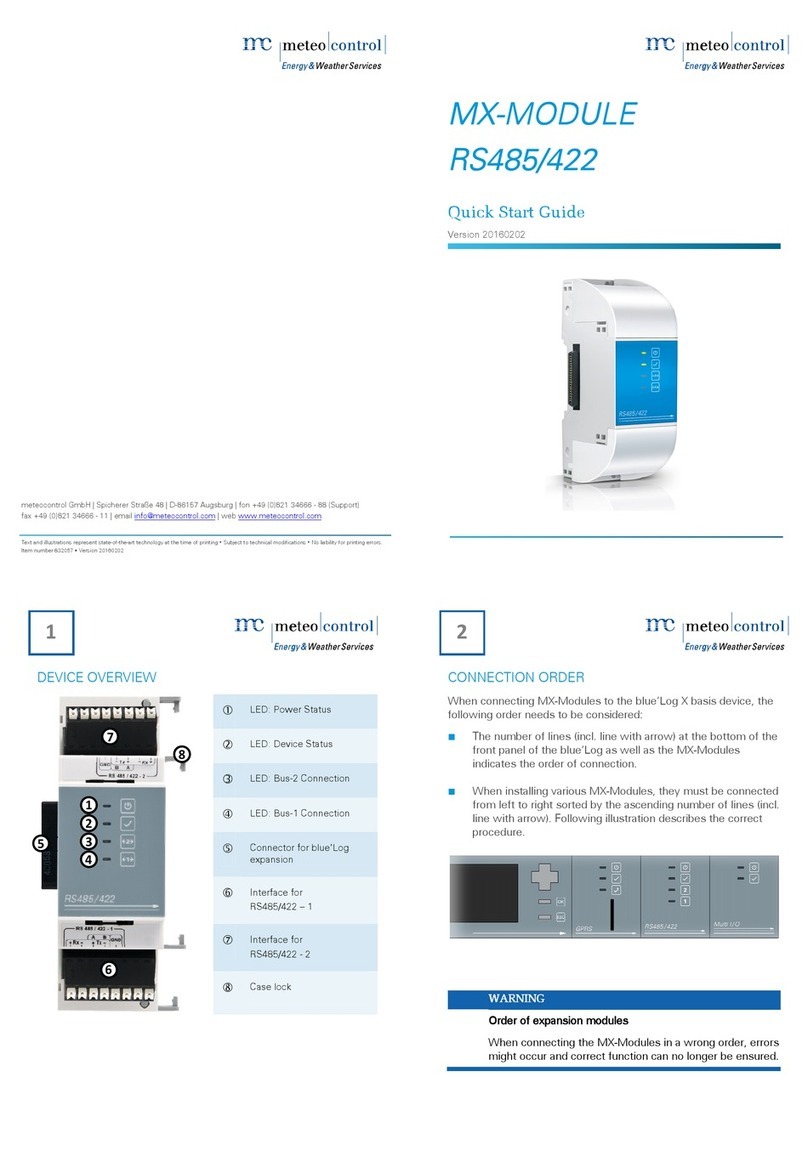
Meteo Control Power Control User manual

Operating manual
meteocontrol Power Control
Version 03082012

2/78 meteocontrol Power Control 03082012 - en
Spicherer Str. 48
D-86157 Augsburg
Tel.: +49 (0) 821 / 3 46 66-0
Web: www.meteocontrol.de
Technical support:
Tel.: +49 (0) 821 / 3 46 66-88
Fax: +49 (0) 821 / 3 46 66-11
© 2012 meteocontrol GmbH
All rights reserved.
All information in these operating instructions has been compiled and
checked with the greatest care and diligence. However, the possibility of
errors cannot be entirely excluded. meteocontrol GmbH therefore cannot
accept any liability for errors or any circumstances resulting from errors.
Subject to technical alterations.

meteocontrol Power Control 03082012 - en 3/78
Contents
Operating manual............................................................................................................1
meteocontrol Power Control............................................................................................1
1.
Use....................................................................................................................6
1.1
Introduction.......................................................................................................6
1.2
About this operating manual .............................................................................6
1.3
Disclaimer.........................................................................................................6
2.
Safety................................................................................................................8
2.1
Meaning of the notices......................................................................................8
2.1.1
Further notices.........................................................................................8
2.2
Product safety...................................................................................................9
2.2.1
Safety instructions for operation..............................................................9
2.2.2
Transportation and storage ...................................................................10
3.
Technical requirements...................................................................................11
3.1
EEG (German Renewable Energy Law) .........................................................11
3.2
meteocontrol Power Control requirements......................................................11
4.
Functionality....................................................................................................12
4.1
meteocontrol Power Control Industrial............................................................12
4.2
Functional display Power Control with WEB`log PRO and PCU.....................13
4.3
Functional display Power Control with WEB`log PRO.....................................14
4.4
Functions ........................................................................................................15
4.4.1
Power control.........................................................................................15
4.4.2
Master functions....................................................................................15
4.4.3
Power requirements change message..................................................15
4.4.4
Deactivation of the alert.........................................................................15
4.4.5
Calculation of the residual energy balance............................................16
4.4.6
Reporting function .................................................................................16
5.
Power Control status WEB`log display............................................................17
5.1
Menu entries in the device display..................................................................17
6.
Power Control config WEB`log browser..........................................................18
6.1
Selection of Modbus device profiles................................................................18
6.2
Assignment of Modbus device profiles............................................................20
6.3
Details on the PCU interface configuration.....................................................21
6.3.1
PCU IP configuration.............................................................................21
6.3.2
PCU serial configuration........................................................................21

4/78 meteocontrol Power Control 03082012 - en
6.3.3
Assignment of the PCU in WEB`log......................................................21
6.4
Details on the PCU device configuration ........................................................22
6.5
Power Control online values...........................................................................26
6.6
Power requirements configuration..................................................................27
7.
Active and reactive power procedures............................................................32
7.1
Active power procedures................................................................................34
7.1.1
P(DI)......................................................................................................34
7.1.2
P(AI)......................................................................................................36
7.1.3
P(DI) internal.........................................................................................37
7.2
Reactive power procedures............................................................................39
7.2.1
cos φ(DI)...............................................................................................39
7.2.2
cos φ(AI) ...............................................................................................41
7.2.3
Control procedure cos φFix..................................................................44
7.2.4
Q(DI) .....................................................................................................45
7.2.5
Power procedures P(DI) and Q(DI) combined.......................................47
7.2.6
Q(AI) .....................................................................................................49
7.2.7
Q fix.......................................................................................................52
7.2.8
Q(U) ......................................................................................................52
7.2.9
cos φ(P) ................................................................................................53
7.2.10
cos φ(U)................................................................................................55
7.3
Details fallback operation................................................................................56
8.
System control circuit......................................................................................57
9.
Application cases............................................................................................59
9.1
Querying Power Control status.......................................................................59
9.2
Power Control power procedures ...................................................................59
9.2.1
Electric installation PCU to WEB`log.....................................................59
9.2.2
Installation PCU to WEB`log .................................................................59
9.2.3
Configuring PCU...................................................................................59
9.2.4
Configuring Power Control....................................................................60
9.3
Power Control system control circuit GCP control..........................................60
9.4
Enabling Power Control..................................................................................60
9.5
Performing test run (optional).........................................................................60
9.6
Power Control slave WEB`log ........................................................................61
10.
The WEB`log..................................................................................................62
10.1
Connection options....................................................................................62

meteocontrol Power Control 03082012 - en 5/78
10.1.1
Ripple control receiver with WEB`log, digital inputs...............................62
10.1.2
WEB`log Pro master - slave ..................................................................63
11.
The Power Control Unit (PCU)........................................................................64
11.1
PCU Connections.......................................................................................64
11.1.1
Description of the elements...................................................................65
11.2
PCU operating elements............................................................................68
11.2.1
Write protect slide switch.......................................................................68
11.2.2
Modbus address coding switch..............................................................68
11.2.3
Modbus bus termination switch .............................................................68
11.3
Installation..................................................................................................68
11.3.1
Safety instructions for installation..........................................................68
11.3.2
Mounting................................................................................................70
11.3.3
Connection options................................................................................72
12.
The plant control circuit/GCP control...............................................................76
13.
Power procedures overview............................................................................76
14.
GlossaryTOA ..................................................................................................77
15.
List of figures...................................................................................................77

6/78 meteocontrol Power Control 03082012 - en
1. Use
1.1 Introduction
This operating manual describes the meteocontrol Power Control function in
connection with the WEB`log data logger, the power control unit (PCU) and
further components for power control.
The full operating manual can be downloaded in electronic form from
meteocontrol’s website.
The meteocontrol Power Control is broken down into three areas:
Homeline, Industrial and Special Solutions
The focus of this documentation is meteocontrol Power Control Industrial for
industrial solutions
Information on Homeline or Special Solutions can be obtained via the
meteocontrol website or the respective sales contacts.
1.2 About this operating manual
This operating manual is intended for plant planners and installers and forms
the basis for a safe operation of meteocontrol Power Control. The personnel
responsible for installation, operation and maintenance must have read and
understood this operating manual
The operating manual must be accessible at all times.
The term WEB`log Pro is used in representation of the WEB`log Pro and
WEB`log Pro Unlimited device types in this manual.
meteocontrol GmbH accepts no liability for personal injury, damage to
property, or malfunctions and their consequences, insofar as these result
from non-observance of this operating manual.
1.3 Disclaimer
meteocontrol rejects any liability for damage arising from the non-observance
of the operating manual.
This applies, in particular, for damage from:
•Unintended use
•Faulty operation
•Wrongly chosen materials and tools
•Faulty or non-executed maintenance and repairs

meteocontrol Power Control 03082012 - en 7/78
With Power Control, meteocontrol shall not be liable for events or
occurrences that are outside its area of influence, such as for the correctness
of the control commands of an energy supplier, non-carrying out of
forwarded control commands, hardware and/or software failures with the
system operator, switching events at the end customer. Any liability for
damage caused by such events and occurrences, such as lost profits, grid
instability, damage to parts of the customer's system, for instance of an
inverter, shall remain expressly excluded.

8/78 meteocontrol Power Control 03082012 - en
2. Safety
2.1 Meaning of the notices
Safety notices are classified by a signal word and corresponding colour. The
different safety notices stated below are explained as follows:
Warning
Type
Consequences
–Indicates a possibly dangerous situation. Death
in the event of electric shock or severe injury with irreversible damage
may be the result.
Notice
Type
Consequences
–Indicates a possibly damaging situation. Material damage to the
system and its immediate environment may be the result.
2.1.1 Further notices
A general notice is a piece of information for better understanding and may
include the following:
•Background information
•Special circumstance
•Further or additional information

meteocontrol Power Control 03082012 - en 9/78
Information about this topic:
Operating manual Refers to another manual
WEB`log WEB`log PRO operating manual
Web portal Documentation Web portal
Inverter Documents on the inverter
2.2 Product safety
Power Control is a system for controlling and steering different operating
parameters of PV systems (such as reactive and active power).
The connections of the data loggers and modules used here may be loaded
with the permissible signals and signal strengths only.
Installation is only permitted indoors. For installation outdoors or in a dusty
environment, the device must be installed in a standardised protective
enclosure.
2.2.1 Safety instructions for operation
The following must be observed when the data logger is in operation:
•Do not remove the memory card (compact flash) or SIM card.
•Do not open the device.
•Do not make any modifications to the device.
•Immediately take damaged devices out of operation and have them
checked by a qualified electrician.
•Observe local provisions when using the device.
•The safety of the device and the operator cannot be guaranteed if the
device is operated in contravention of the described safety instructions

10/78 meteocontrol Power Control 03082012 - en
2.2.2 Transportation and storage
Inspect the device for transport damage on delivery. Notify the transport
company in the event of visible damage.
A damaged device must not be put into operation!
Transport the device in original packaging only. Protect the device from dust
and moisture.
Further information about this topic:
Operating manual end customer Technical data

meteocontrol Power Control 03082012 - en 11/78
3. Technical requirements
3.1 EEG (German Renewable Energy Law)
The necessity of active participation of operators of PV systems in the grid
safety management increases with the rising share in the overall power
production. This requires an option to reduce the feed-in power and
participation in the compensation of the reactive power in the grid.
As such, the plant operators must fulfil the following requirements:
•They must be able to reduce the feed-in capacities of plants by remote
control or disconnect plants from the grid entirely.
•They must be able to reduce the reactive power in the grid by reactive
power compensation.
3.2 meteocontrol Power Control requirements
It is recommended to clarify the following requirements of the energy
supplier, inverter manufacturer and plant operator for the Power Control
already in the phase of plant planning:
•Power procedures according to which the requirements of the energy
supplier are implemented in control values for the inverters.
•Power procedures that are supported by WEB`log PRO for the inverter
types used (inverter drivers).
•Characteristic requirements for the power procedure made by the system
operator:
Note: If difficulties regarding the requirement areas arise or
necessary configuration options are not available, consult
your sales contact at meteocontrol.

12/78 meteocontrol Power Control 03082012 - en
4. Functionality
4.1 meteocontrol Power Control Industrial
Basic function:
•The requirements for power reduction and control are received from the
energy supplier via a selected interface (digital, analogue, IEC 60870-5-
101) by PCU or WEB`log PRO inputs.
•The control values are determined from the requirements in accordance
with configurable rules. The rules can be defined in accordance with the
requirements. Feedback to the operator is derived optionally.
•The control values are set on the inverter within a response time required
by the energy supplier.
•The energy supplier receives a message about the control value set on
the inverters.

meteocontrol Power Control 03082012 - en 13/78
4.2 Functional display Power Control with WEB`log PRO and
PCU
safer Sun
P/Q
P/Q
123
12
10
11
6
5
4
7
8
9
9
8
13
9
Fig. 1: Functionality PCU<>Power Control
(1) Energy supplier (8) WEB`log PRO as slave
(2) Public grid (9) Inverter
(3) Ripple control receiver (10) Internet
(4) Central computer (11) Web portal
(5) Power control unit (PCU) (12) Power requirements report
(6) WEB`log PRO as master (13) Alert, residual energy balance report
(7) Ethernet switch

14/78 meteocontrol Power Control 03082012 - en
4.3 Functional display Power Control with WEB`log PRO
safer Sun
P
P
123
10
11
65
4
7
98
7
6
7
Fig. 2: Functionality Power Control
(1) Energy supplier (7) Inverter
(2) Public grid (8) Internet
(3) Ripple control receiver (9) Web portal
(4) WEB`log master (10) Power requirements report
(5) Ethernet switch (11) Alert, residual energy balance
(6) WEB`log slave Report

meteocontrol Power Control 03082012 - en 15/78
4.4 Functions
4.4.1 Power control
P
P/Q
Active power procedure (P procedure)
With the internal inputs of the WEB`log PRO only the active
power procedure can be carried out via digital requirements,
Active and reactive power procedures (P/Q/cos φprocedures)
With the PCU different active and reactive power procedures
can be selected and configured.
4.4.2 Master functions
In larger plants with several WEB`log PRO devices, a WEB`log
PRO assumes the master function.
The master receives the requirement values from the energy
supplier. The information is forwarded to all WEB`log PRO
devices (slaves) or the configured IP addresses via Ethernet
using a broadcast.
4.4.3 Power requirements change message
When changing the power requirements, the WEB`log PRO
informs one or more recipients via the reporting route
configured.
The message contains information on the time of changing and
the required power level.
4.4.4 Deactivation of the alert
(portal function, in preparation)
In the event of an enforced reduction, certain alerts are
deactivated for the duration of the reduction (e.g. comparison
energy to irradiance).
The SaferSun internet portal identifies the required reduction
and deactivates the alerts for this period.

16/78 meteocontrol Power Control 03082012 - en
4.4.5 Calculation of the residual energy balance
(portal function, in preparation)
Provides an overview of the energy not fed in.
The residual energy balance is calculated from the energy
quantity of the daily simulation and the energy actually fed in
on this day and saved and displayed in the internet portal.
4.4.6 Reporting function
(portal function, in preparation)
Reports can be created, which provide detailed information in
the event of a reduction.

meteocontrol Power Control 03082012 - en 17/78
5. Power Control status WEB`log display
The status of the Power Control can be queried and modified via the device
display. The configuration is possible via the browser only.
Fig. 3: Power Control settings
Note: The PC settings are available via the installer login only.
Default 0010
5.1 Menu entries in the device display
PC status
•Active: Power Control is active
•Inactive: Power Control is inactive

18/78 meteocontrol Power Control 03082012 - en
6. Power Control config WEB`log
browser
Administrator rights are required to configure the meteocontrol Power Control
in WEB`log.
Login procedure for configuration websites
1. Select the "Profi page" in the start centre.
2. Select the "General" menu item.
3. Select "Login".
4. Enter the administrator password and click "Login"
(default: ist02)
The WEB`log page for device configuration is displayed in the web
browser,
6.1 Selection of Modbus device profiles
Both the power control unit (PCU) and the power quality analyser (PQA) are
connected to the WEB`log via the Modbus protocol.
To this end, the required device types from the list of available devices must
be selected and saved.
Under the "Admin Measurement" menu item, "General configuration" item,
the required Modbus settings and Modbus device types are selected.
Fig. 4: Selection of the Modbus settings and Modbus device types

meteocontrol Power Control 03082012 - en 19/78
General information
Input field Meaning
Modbus driver version Current driver software version
Serial interface settings
Input field Meaning
Modbus Modbus protocol used, ASCII or RTU,
standard: RTU
Baud rate Baud rate of the serial interface
Standard: 9600 Baud
Data bits \ Parity \ Stop bits Definition of the serial protocol
Standard: 8/N/1
Scan for Modbus message used for scanning
Read new device types
The interface used is assigned via the suffix in the file name of the PCU
device type:
Input field Meaning
pcu_rtu.mod PCU Modbus via RTU (standard)
pcu_tcp.mod PCU Modbus via TCP
janitza_umg604_rtu.mod NAG Modbus via RTU (standard)
janitza_umg604_tcp.mod NAG Modbus via TCP
Save Saves the settings made
Note: Modbus TCP requires no configuration of the interfaces.

20/78 meteocontrol Power Control 03082012 - en
6.2 Assignment of Modbus device profiles
Under "Admin Measurement" menu item, "Device configuration" item the
Modbus device type is assigned for the corresponding Modbus client ID.
Fig. 5: Assignment Modbus client ID to the device type
Add serial device
Input field Meaning
Address Client ID of the Modbus device.
Device type Device type of the Modbus device
Scan for serial devices
Input field Meaning
Address space scan Number of client IDs to be scanned (standard:
1-20). Scan duration depending on the size of
the address range up to one minute.
Scan After a successful scan, the devices found are
listed under „Device configuration“
Add TCP/IP device
Input field Meaning
IP address Input of the IP address
Table of contents
Other Meteo Control Control Unit manuals
Popular Control Unit manuals by other brands
WAPRO
WAPRO WAGATE SVM-TG125 Installation & maintenance
USR IOT
USR IOT USR-WIFI232-A2 Hardware manual

Advanced Solar Photonics
Advanced Solar Photonics ASP-390M Safety & instruction manual
Festo
Festo CPX-FVDA-P Description
Linear Technology
Linear Technology DC1589A Quick start guides
V2
V2 City7 instruction manual
