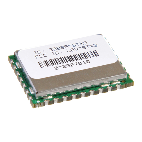
Globalstar ST150 User manual

ST150 MODULE
User Manual
9150-0125-01 R-4

9150-0125-01 R-4
II
Distribution Statements:
GLOBALSTAR CONFIDENTIAL AND PROPRIETARY INFORMATION – All data and information contained
in this
document are confidential and proprietary to Globalstar, Inc. Information and instructions contained in this publication
anticipate the user possesses and applies the knowledge, training, and experience commensurate with requirements
to meet prerequisite certification. All handling and distribution of this document is subject to the terms & conditions
of the Non-Disclosure Agreement currently in place between Globalstar, Inc. and the recipient.
RESTRICTIVE EXPORT NOTICE – This document may contain technical data whose export is restricted by
the Export
Administration Act of 1979, as amended, Title 50, U.S.C., App 2401 et seq. Violations of these export laws are subject to
severe criminal penalties. Do not export, directly or indirectly, any technical data or defense information, or any products
utilizing any such data, to any country for which the U.S. Government or any agency thereof, requires an export license,
according to their laws and regulations or other Government approval, without first obtaining such license or written
approval.
DESTRUCTION NOTICE – Destroy by any method that will prevent disclosure of contents or reconstruction of
the
document.
Published and printed in the U.S.A. by:
Globalstar, Inc.
1351 Holiday Square Blvd.
Covington, LA 70433
Copyright
©2022
Globalstar,
Inc.
All
rights
reserved.
Globalstar®
is
a
registered
trademark
of
Globalstar,
Inc.
All
other
brands,
product
name,
trademarks
and
registered trademarks are properties of their respective owners. This material may not be reprinted, republished,
broadcast, or otherwise altered without the publisher’s written permission. This manual is provided without
express, statutory, or implied warranties. The publisher will not be held liable for any damages caused by or
alleged to be caused by use, misuse, abuse, or misinterpretation of the contents.
Content is subject to change
without notice.
Revision
date:
04/28/2022

9150-0125-01 R-4
ST150M User Manual
Confidential & Proprietary Information
3
CONTENTS
LIST OF FIGURES
..........................................................................................................................7
1
INTRODUCTION
......................................................................................................................8
1.1
PURPOSE
.......................................................................................................................................................... 8
1.2
APPLICABLE DOCUMENTS
.......................................................................................................................................... 8
1.2.1
GLOBALSTAR DOCUMENTS
........................................................................................................................ 8
1.2.2
EXTERNAL REFERENCES
.......................................................................................................................... 8
1.3
DESCRIPTION
.................................................................................................................................................... 9
1.3.1 Feature List ........................................................................................................................................... 9
1.4
CERTIFICATIONS
...............................................................................................................................................11
2
APPLICATION
.......................................................................................................................12
2.1
THEORY OF OPERATION FOR GLOBALSTAR COMMERCIAL IoT
.................................................................................................12
2.2
QUICK START/CONFIGURATION GUIDELINES
.......................................................................................................................13
2.3
BLOCK DIAGRAM
....................................................................................................................................................14
2.4
CORE COMPONENTS
...............................................................................................................................................14
2.4.1 Nordic SoC ...........................................................................................................................................14
2.4.2 ASIC satellite transmitter.......................................................................................................................14
2.4.3 GNSS receiver ......................................................................................................................................15
2.4.4 Memory................................................................................................................................................15
2.4.5 Accelerometer ......................................................................................................................................15
2.4.6 Program and debug ..............................................................................................................................15
2.4.7 DC Supply ............................................................................................................................................15
3
POWER MANAGEMENT
...........................................................................................................16
3.1 Power Management High Level Overview..........................................................................................................16
4
PERIPHERALS
.........................................................................................................................18
4.1 Near-Field Communication (NFC)......................................................................................................................18
4.2 GPIO pin peripherals .......................................................................................................................................18
4.2.1GPIO....................................................................................................................................................19
4.2.2 Comparator ..........................................................................................................................................19
4.2.3 PDM - Pulse Density modulation interface ..............................................................................................20
4.2.4 PPI - Programmable Peripheral Interconnect ..........................................................................................20
4.2.5 PWM - Pulse Width Modulation ..............................................................................................................20
4.2.6 QDEC - Quadrature Decoder..................................................................................................................20
4.2.7 RTC - Real Time Counter.......................................................................................................................21
4.2.8 SPI - Serial Peripheral Interface.............................................................................................................22
4.2.9 UART - Universal asynchronous receiver / transmitter .............................................................................22
4.3 Using and Enabling Peripheral Devices..............................................................................................................23
5
HARDWARE LAYOUT/REFERENCE DESIGN
.......................................................................................26
5.1 Pin Assignments ..............................................................................................................................................26
5.2 Reference Circuitry ..........................................................................................................................................30
5.2.1 PCB Guidelines .....................................................................................................................................30

9150-0125-01 R-4
ST150M User Manual
Confidential & Proprietary Information
4
5.2.2 Module Dimensions...............................................................................................................................30
5.2.3 PCB Layout Example .............................................................................................................................31
5.3 Reference Design Schematics...........................................................................................................................34
5.4 Transmit/Receive Antenna Requirements..........................................................................................................35
5.5 BLE Antenna Requirements..............................................................................................................................35
5.6 Single Modular Approval Requirements .............................................................................................................36
5.7 Trace and Cable Losses ...................................................................................................................................36
6
RECOMMENDED OPERATING CONDITIONS
......................................................................................37
6.1
ABSOLUTE MAXIMUMS
.............................................................................................................................................37
6.2
HANDLING OF ELECTROSTATIC SENSITIVE DEVICES
.........................................................................................................37
6.3
WIRING
...........................................................................................................................................................37
6.4
NOISE SOURCES
...................................................................................................................................................37
6.5
NORDIC PROCESSOR UNUSED PINS
...........................................................................................................................38
6.6
OBSTRUCTIONS
.................................................................................................................................................38
7
APPLICATION PROGRAMMING INTERFACE (API)
..............................................................................38
7.1 AT Commands.................................................................................................................................................38
7.1.1
ST150 Device Configuration
.......................................................................................................................38
7.1.2 Configuration Security...........................................................................................................................38
7.1.3 General Configuration ...........................................................................................................................39
7.2URC Notification Settings .................................................................................................................................40
7.2.1 Transmitter Event Notification Settings...................................................................................................40
7.2.2 Set Transmitter Notify Flags via NUS, UART............................................................................................40
7.2.3 Read Transmitter Notify Flags via NUS, UART.........................................................................................41
7.2.4 Set Transmitter Notify Flags via Configuration Service.............................................................................41
7.2.5 Read Transmitter Notify Flags via Configuration Service ..........................................................................41
7.3 Message Queue Event Notification Settings.......................................................................................................41
7.3.1 Set Message Queue Notify Flags via NUS, UART .....................................................................................41
7.3.2 Read Message Queue Notify Flags via NUS, UART...................................................................................41
7.3.3 Set Message Queue Notify Flags via Configuration Service ......................................................................41
7.3.4 Read Message Queue Notify Flags via Configuration Service....................................................................41
7.4 GPIO Event Notification Settings ......................................................................................................................42
7.4.1 Set GPIO Notify Flags via NUS, UART .....................................................................................................42
7.4.2 Read GPIO Notify Flags via NUS, UART ..................................................................................................42
7.4.3 Set GPIO Notify Flags via Configuration Service ......................................................................................42
7.4.4 Read GPIO Notify Flags via Configuration Service ...................................................................................42
7.5 Inputs/Count Event Notification Settings...........................................................................................................42
7.5.1 Set Inputs/Count Notify Flags via NUS, UART .........................................................................................42
7.5.2 Read Inputs/Count Notify Flags via NUS, UART ......................................................................................42
7.5.3 Set Inputs/Count Notify Flags via Configuration Service ..........................................................................43
7.5.4 Read Inputs/Count Notify Flags via Configuration Service........................................................................43
7.6 Track events Notification Settings.....................................................................................................................43
7.6.1 Set Track Events Notify Flags via NUS, UART..........................................................................................43
7.6.2 Read Track Events Notify Flags via NUS, UART .......................................................................................43

9150-0125-01 R-4
ST150M User Manual
Confidential & Proprietary Information
5
7.6.3 Set Track Events Notify Flags via Configuration Service...........................................................................43
7.6.4 Read Track Events Notify Flags via Configuration Service ........................................................................43
7.7 System OTA Event Notification Settings ............................................................................................................44
7.7.1 Set OTA Events Notify Flags via NUS, UART............................................................................................44
7.7.2 Read OTA Events Notify Flags via NUS, UART.........................................................................................44
7.7.3 Set OTA Events Notify Flags via Configuration Service.............................................................................44
7.7.4 Read OTA Events Notify Flags via Configuration Service ..........................................................................44
7.8 GPS Event Notification Settings ........................................................................................................................45
7.8.1 Set GPS Notify Flags via NUS, UART.......................................................................................................45
7.8.2 Read GPS Notify Flags via NUS, UART. ...................................................................................................45
7.8.3 Set GPS Notify Flags via Configuration Service........................................................................................45
7.8.4 Read GPS Notify Flags via Configuration Service .....................................................................................45
7.9 Accelerometer Event Notification Settings .........................................................................................................46
7.9.1 Set Accelerometer Event Notify Flags via NUS, UART..............................................................................46
7.9.2 Read Accelerometer Event Notify Flags via NUS, UART. ..........................................................................46
7.9.3 Set Accelerometer Event Notify Flags via Configuration Service ...............................................................46
7.9.4 Read Accelerometer Event Notify Flags via Configuration Service.............................................................46
7.10 Power Management Event Notification Settings .................................................................................................46
7.10.1 Set Power Management Notify Flags via NUS, UART...............................................................................47
7.10.2 Read Power Management Notify Flags via NUS, UART.............................................................................47
7.10.3 Set Power Management Notify Flags via Configuration Service.................................................................47
7.10.4 Read Power Management Notify Flags via Configuration Service ..............................................................47
7.11 External Flash Logging Event Notification Settings .............................................................................................47
7.11.1 Set External Flash Logging Notify Flags via NUS, UART...........................................................................47
7.11.2 Read External Flash Logging Notify Flags via NUS, UART.........................................................................47
7.11.3 Set External Flash Logging Notify Flags via Configuration Service ............................................................47
7.11.4 Read External Flash Logging Notify Flags via Configuration Service..........................................................48
7.12 GPIO/Inputs Configuration...............................................................................................................................48
7.12.1 Getting a list of all the GPIO. .................................................................................................................48
7.12.2 Configuring Inputs ................................................................................................................................49
7.12.3 Mapping Inputs ....................................................................................................................................50
7.12.4 Getting the Input State of Mapped Inputs ..............................................................................................50
7.12.5 GPIO Notify Settings .............................................................................................................................51
7.13 Enabling and Configuring the UART ..................................................................................................................52
8
SOFTWARE HIGH LEVEL OVERVIEW
...............................................................................................52
8.1 BLE Configuration Service and Interfaces..........................................................................................................52
8.1.1 Device Advertising and Discoverability....................................................................................................53
8.1.2 External Interfaces................................................................................................................................53
8.1.3 External Interface Security ....................................................................................................................53
9
UNIFIED API MODULES
.........................................................................................................54
9.1 Messages........................................................................................................................................................55
9.1.1 Message Priority ...................................................................................................................................55
9.1.2 Burst Count ..........................................................................................................................................55

9150-0125-01 R-4
ST150M User Manual
Confidential & Proprietary Information
6
9.1.3 Min/Max Burst Interval Seconds.............................................................................................................56
9.1.4 Interval and Time-Of-Day Message List ..................................................................................................56
9.1.5 Transmitter ..........................................................................................................................................56
9.1.6 Message Preemption and Aborted Transmissions ....................................................................................56
9.1.7 GPIO....................................................................................................................................................57
9.1.8 Special Function Inputs .........................................................................................................................57
9.1.9 UART ...................................................................................................................................................58
9.1.10 GPIO Events.........................................................................................................................................58
9.1.11 Inputs ..................................................................................................................................................58
9.1.12 OTA Messages......................................................................................................................................58
9.1.13 Input Events.........................................................................................................................................58
9.1.14 Track Functions ....................................................................................................................................58
9.1.15 GPS Module..........................................................................................................................................59
9.1.16 Accelerometer Module...........................................................................................................................60
9.1.17 Power Management ..............................................................................................................................61
9.1.18 Temperature Notifications .....................................................................................................................61
9.1.19 Data Logging........................................................................................................................................62
9.1.20 BLE Settings .........................................................................................................................................62
10
TEST MODES
.....................................................................................................................63
10.1 Transmitter Test Modes ...................................................................................................................................63
11
ORDERING INFORMATION/DEVICE MARKINGS/ACTIVATION INFORMATION
.......................................64
11.1 Device Marking ...............................................................................................................................................64
11.2 Box Labels ......................................................................................................................................................64
11.3 How to Order ..................................................................................................................................................65
11.4 Globalstar Product Certification ........................................................................................................................66
12
GENERAL WARNINGS
..........................................................................................................67
13
REGULATORY
..................................................................................................................68
14
ACRONYM LIST
.................................................................................................................71

9150-0125-01 R-4
ST150M User Manual
Confidential & Proprietary Information
7
LIST OF FIGURES
FIGURE 1 - PHYSICAL DIMENSIONS ............................................................................................................ 11
FIGURE 2 - LEO CONSTELLATION ............................................................................................................... 12
FIGURE 3 - SIMPLEX IOT MESSAGING DATA FLOW ...................................................................................... 12
FIGURE 4 - OVERALL MODULE SYSTEM ....................................................................................................... 14
FIGURE 5 – PIN ASSIGNMENTS................................................................................................................... 26
FIGURE 6 – MODULE DIMENSIONS ............................................................................................................. 30
FIGURE 7 – TOP AND BOTTOM LAYOUTS.................................................................................................... 31
FIGURE 8 – STX/GPS LAYOUT .................................................................................................................... 32
FIGURE 9 – BLE LAYOUT............................................................................................................................ 32
FIGURE 10 – TOP AND BOTTOM PCB VIEWS............................................................................................... 33
FIGURE 11 – STX/GPS, BLE VIEWS (LEFT TO RIGHT) .................................................................................. 33
FIGURE 12 - COPLANAR WAVEGUIDE .......................................................................................................... 36
FIGURE 13 - UNIFIED API MODULES ........................................................................................................... 54
FIGURE 14 – PCB LABEL ............................................................................................................................ 64
FIGURE 15 – BOX LABEL AND PACKING SLIP ....................................................................................... 64

9150-0125-01 R-4
ST150M User Manual
Confidential & Proprietary Information
8
1
INTRODUCTION
1.1
PURPOSE
This document describes the physical, electrical, and functional characteristics of the ST150 Satellite
Transmitter Module, hereafter referred to as ST150M. The information contained in this document is intended
to provide the VAR/Integrator with the necessary technical information required to configure and use the
module in a custom application.
This document is intended to be used by engineers and technical management and assumes a general
knowledge of basic engineering practices by the user. NOTE: Globalstar is only responsible for ensuring that
the ST150M meets the published manufacturing specifications described herein.
1.2
APPLICABLE DOCUMENTS
1.2.1
GLOBALSTAR DOCUMENTS
GS-07-1248 - REMOTE TELEMETRY SERVICE FREQUENCY PLAN FOR SIMPLEX TRANSMITTERS
GS-07-1247 - REMOTE TELEMETRY SERVICE SIMPLEX ANTENNA SPECIFICATION AND TEST PROCEDURE
GS–02-0795 - REMOTE SIMPLEX TELEMETRY SYSTEM DESCRIPTION AND APPLICATION NOTE
GS-09-1302 - GLOBALSTAR EQUIPMENT EVALUATION APPLICATION FOR REMOTE TRANSMITTER UNIT
9150-0126-01 ST150 INTEGRITY USER GUIDE
9150-0127-01- ST150M APP USER GUIDE
8545-0196-01 - GLOBALSTAR ST150M PRODUCT SUBMISSION GUIDE
8550-0002-01 - ST150M UNIFIED API REFERENCE
8550-0006-01 - ST150 SOFTWARE DESIGN GUIDE
8550-0003-01 - GLOBALSTAR ST150 BLUETOOTH SENSORS USER GUIDE
8550-0004-01 - GLOBALSTAR ST150 BLUETOOTH REFERENCE
8550-0010-01 - GLOBALSTAR IOT ASIC DFU SERVICE BLE SPECIFICATION
8550-0009-01 - GLOBALSTAR IOT CONFIGURATION SERVICE BLE SPECIFICATION
8550-0008-01 - GLOBALSTAR IOT SENSOR SERVICE BLE SPECIFICATION
1.2.2
EXTERNAL REFERENCES
Wikipedia article on Intel Hex format: https://en.wikipedia.org/wiki/Intel_HEX
NMEA-0183 rev. 3.0 Specification
FCC Guidance for Use of Radio Modules KDB 996369 D03 & D04
•
Nordic Programmer (Segger):
https://www.digikey.com/product-detail/en/segger-microcontroller-systems/8-08-00-J-LINK-BASE/899-1004-ND/2175882
•
ASIC Programmer (On Semi):
https://www.digikey.com/product-detail/en/on-semiconductor/AXDBG-2-GEVK/AXDBG-2-GEVK-ND/5820231

9150-0125-01 R-4
ST150M User Manual
Confidential & Proprietary Information
9
1.3
DESCRIPTION
The ST150M is a transmit-only Satellite IoT module designed to send small packets of user defined data to a
network of low earth orbiting (LEO) satellites using the Globalstar commercial IoT network. The received data
is then forwarded to a user defined network interface that may be in the form of an FTP host, HTTPS host or
HTTP host where the user will interpret the data for further processing.
The ST150M is designed to be integrated into an integrator’s custom carrier board design. The ST150M can
operate 100% autonomously once configured, can be controlled via external interfaces/AT commands, or can be
modified with custom firmware leveraging the onboard Nordic 52840 as the applications processor.
The ST150M can be configured via the Globalstar Mobile App, through the BLE configuration service, or through
a physical or BLE-based UART.
The ST150M includes value-added software modules that can be configured for tracking applications based on
GPS and/or accelerometer movement detection, input-based count, accumulate, state, and transition events,
interval or time-of-day events, and even Smart One Sensor Service data.
The ST150M consists of the Nordic NRF52840, External Flash, GPS, accelerometer, ASIC, and internal power
controls. It does not have an onboard patch antenna. The Nordic and ASIC are shielded for modular
certification. The ST150M has gold “fingers” around the perimeter of the PCB so that it can be SMT-installed
onto a carrier board or another custom PCB.
1.3.1 Feature List
Hardware
Attributes
•
54 pin SMT
•
2 x 1.1 inches
•
3.3V VCC
•
Nordic 52840 MCU
•
Onboard GPS and 3-axis accelerometer
•
Onboard satellite ASIC transmitter
•
Onboard/Offboard MCU programming
•
Onboard/Offboard ASIC programming
•
Integrated voltage regulation
•
GPS RF signal
•
ASIC RF signal
•
BLE RF signal
•
NFC RF signal
•
24 configurable I/O
•
MCU USB Device
•
I
2
C
Power
•
Nominal: < 100uA
•
Sat Burst: 1.6A
•
GPS on: 50mA
•
BLE connection: variable and customizable
Temperature
•
Operating -40 to 85C
GPS
•
Active and passive antennas
•
72-channel GPS/QZSS L1 C/A, GLONASS L10F, BeiDou B1l,
Galileo E1B/C, SBAS L1 C/A, WAAS, EGNOS, MSAS, GAGAN
•
Tracking: -167 dBm
•
Cold Starts: -148 dBm
•
Hot Starts -157 dBm
•
Accuracy: 2.0m CEP
Accelerometer
•
3-axis acceleration
•
Selectable +/-2G, +/-4G, +/-16G scales
•
6D orientation detection

9150-0125-01 R-4
ST150M User Manual
Confidential & Proprietary Information
10
Software
Security
•
Interface-based security policies for configuration
commands
o
Always disabled
o
Always enabled
o
Passphrase auth required
o
Passphrase auth required with timeout
•
Customizable user passphrase
•
Encrypted BLE configuration interface
Interface
•
Modem AT command interface
o
UART
o
BLE Config (secure key)
o
BLE Nordic UART Service (NUS)
•
Unsolicited response codes (URCs)
o
Customizable event filters
o
Selectable output GPIO interrupts
•
BLE Smart One Sensor Service
o
Up to 10 BLE sensor nodes
o
Customizable security key
Tracking
•
Normal Track Mode
o
Previous track point option
o
Dock mode option
•
Theft Alert Mode
o
Geofencing
•
Integrated or external GPS
•
Integrated or external accelerometer
Software Inputs
•
8-Software Defined Count Inputs
o
GPIO mapping
o
Accelerometer event mapping
•
Count
•
Accumulated Time
•
Transition Events
•
Undesired State
o
Optional hysteresis
OTA Messages
•
3 customizable priority settings
•
Customizable dither and re-transmission attempts
•
Legacy Message Compatibility
o
Raw Messages
o
Truncated Messages
o
Standard Messages
Optional previous track point
o
Speed and Heading
Optional previous track point
o
Smart One Sensor Raw and Truncated Sensor
Messages
•
Modular Messages
o
Powered-On
o
GPS
o
Timestamp
o
Inputs 1-8
•
Health Check
•
Interval or Time-Of-Day
Managed OTA Message Transmit Queue
•
Supports up to 10 pending OTA messages
•
Pre-emption settings
o
Disabled
o
Priority
o
Time
o
Priority and Time
Configurable GPIO
•
Special Function
o
Line Power Detection
o
Advertising Enable Detection
o
Tamper Detection
•
GPS Features
o
NMEA pass-through
o
Current and previous position information
•
Power Management
o
Settable power states and track-mode behavior
Full-on
Partial Suspend
Full Suspend

9150-0125-01 R-4
ST150M User Manual
Confidential & Proprietary Information
11
The ST150M weighs ~0.27oz (7.6g) with shield (no battery, no solar panel), with the dimensions shown below:
1.4
CERTIFICATIONS
Globalstar products comply with WEEE and RoHS. The ST150M has the following certifications:
•
Bluetooth® SIG
•
FCC
•
ISED
•
CE RED
•
UKCA
•
ANATEL
FIGURE 1 - PHYSICAL DIMENSIONS

9150-0125-01 R-4
ST150M User Manual
Confidential & Proprietary Information
12
2
APPLICATION
2.1
THEORY OF OPERATION FOR GLOBALSTAR COMMERCIAL IOT
The ST150M IoT Module operates on the Globalstar LEO satellite network. LEO (Low Earth Orbit) means that
there are a number of satellites in low earth orbit that constantly orbit the planet and can communicate with
Globalstar devices that are within range of its current position.
Because the satellite position is constantly changing, commercial IoT devices on the ground will transmit
(with no knowledge of any of the satellites locations) and the transmission may be received by one or more
satellites. These satellites will then relaythe message to the nearest satellite gateway (Figure 3). Once
received by the satellite gateway, the simplex message will be delivered to the simplex gateway where
redundant messages are discarded and the data from the message is sent to the OEM via the Internet.
FIGURE 3 - SIMPLEX IOT MESSAGING DATA FLOW
FIGURE 2 - LEO CONSTELLATION

9150-0125-01 R-4
ST150M User Manual
Confidential & Proprietary Information
13
2.2
QUICK START/CONFIGURATION GUIDELINES
To get up and running, the following details both mandatory and optional steps:
1. Globalstar offers an ST150M Dev Kit that provides a quick way to power-up the module and
communicate with modem AT command interface via physical UART, Globalstar Mobile App, or BLE
Nordic UART Service (NUS)
2. Create an Account
a. Create a VAR account and access the Globalstar IoT Data Management Portal (Requires
VAR/VAM BackOffice endpoint to route device traffic to)
b. Or, work with a Globalstar VAR to setup billing, activate your module, and create a user login
account (Requires backoffice endpoint to route device traffic to)
c. Or, use Davra’s IoT platform to setup billing, activate your module, and direct device traffic to
your Davra account (Does not require separate backoffice endpoint)
3. Optionally, if using 2A or 2B, integrate backoffice APIs with the Globalstar Simplex API for
programmatic API access to billing and device management APIs
4. Optionally, if using 2A or 2B, access Globalstar’s Data Warehouse Portal for real-time debugging of
device traffic
5. Get the Globalstar Mobile App and use your account credentials from step 2 to login, configure your
device, and sync device activation status
6. Optionally, send a raw or truncated message via modem AT commands to initiate device OTA traffic

9150-0125-01 R-4
ST150M User Manual
Confidential & Proprietary Information
14
2.3
BLOCK DIAGRAM
The ST150M Block Diagram illustrates the overall module system.
2.4
CORE COMPONENTS
2.4.1 Nordic SoC
The ST150M contains a Nordic nRF52840, which utilizes an ARM Cortex-M4 processor with integrated
communication protocols including Bluetooth 5.0, NFC, I2C, SPI, UART and Client USB.
Details on the nRF52840 SOC can be found in documentation from Nordic Semiconductor:
https://infocenter.nordicsemi.com/index.jsp?topic=%2Fug_nrf52840_dk%2FUG%2Fdk%2Fintro.html
2.4.2 ASIC satellite transmitter
The ST150M contains a Globalstar proprietary ASIC used for all satellite transmission and related operations
including signal modulation, channelization, and amplification.
Communication is handled over UART interface bus connecting to the MPU.
FIGURE 4 - OVERALL MODULE SYSTEM

9150-0125-01 R-4
ST150M User Manual
Confidential & Proprietary Information
15
2.4.3 GNSS receiver
The ST150M contains a UBLOX ZOE-M8Q GNSS SiP (System in Package) module with integrated SAW filter and
front-end LNA, plus additional external LNA control line. Both the GNSS RF input and the external LNA control
output is available on ST150M’s edge connector interface.
With a dual-frequency RF front-end the ZOE-M8Q can receive concurrently from three GNSS systems (GPS /
Galileo together with BeiDou or GLONASS).
Communication is handled over GPS_SPI interface bus connecting to the MPU.
2.4.4 Memory
The ST150M contains 64Mb (8MB) of ultra-low power flash memory accessed over QSPI bus. In addition, the
nRF52840 has 1024 kB of flash and 256 kB of RAM located on the SoC.
2.4.5 Accelerometer
The ST150M contains a 3-axis accelerometer capable of 4098 LSB/g (// 16g), with scaling options of 2g, 4g, 8g
and 16g, and high shock survivability of up to 10,000g.
The accelerometer can be communicated with over I2C using 16-bit data output and 32-level FIFO buffer. An
interrupt pin connects to P0.17 of the nRF52840 for configurable motion detect signaling.
2.4.6 Program and debug
The ST150M has dedicated programming and debug ports for both the Nordic SoC and the ASIC.
Nordic programming and debug occurs over signals SWDCLK, RESET, SWDIO which are fed to gold finger pads
46, 47, 48 and to 0.5 MIL (1.27mm) header J1 (depopulated).
ASIC programming occurs over signals SAT_DBG_CLK, SAT_DBG_EN, SAT_RST_N, SAT_DBG_DATA which are fed
to gold finger pads 50, 51, 52, 53 and to 1 MIL (2.54mm) header J2 (depopulated).
2.4.7 DC Supply
Using separate DC sources can help to reduce noise on the system, maintain efficiency, and improve signal
integrity for transmissions. ST150M divides power input between VRF_IN and V33_IN.
VRF_IN powers the ASIC RF circuitry.
V33_IN powers everything else on the ST150M including ASIC digital circuitry and GNSS receive.
VRF_EN is an active-high 0-3V control output to indicate if currently transmitting. Connect VRF_EN to the enable
pin of VRF_IN supply.
VRF_IN and V33_IN can be tied together using a single source if desired. VRF_EN should remain floating if a
single source is used.

9150-0125-01 R-4
ST150M User Manual
Confidential & Proprietary Information
16
3POWER MANAGEMENT
Note: -40º to +85ºC operating temperature
3.1 POWER MANAGEMENT HIGH LEVEL OVERVIEW
The Power UAPI is responsible for handling the different power states of the UAPI and switching between them.
The power states are based on configurable battery voltage thresholds. This module also handles the required
action before moving into a powered down state.
Power States
There are five different power states that have different limitations on them to control the amount of power of
the module:
•Normal: The device runs as normal with no restrictions.
•Factory: Same as normal, but if no solar input is detected for four hours, the device goes into the Full
Off state. This is the default state of the device when the factory configuration is on the device. Once
the user updates the configuration, this mode is inaccessible.
•Partial Suspend: The device is limited on the frequency of track messages it can send to reduce power
consumption.
•Full Suspend: The device cannot send any track messages.
•Full Off: The device sends a command to the fuel gauge to fully disconnect the ST150 module from
power. Only light on the solar panel can wake the device up from this state.
Signal
Parameter
Range
Nom.
Units
Notes
V33_IN Input Voltage Range for Digital Inputs 3.1 – 3.6 3.3 Volts
50mV ripple max, 80uA
– 200mA depending on
BLE/GPS power and
usage
I33_IN Input Current for Digital Inputs 100 max – mA
VRF_IN Input Voltage Range for RF circuitry 3.0 -3.6 3.3 Volts
50mV ripple max, 1.6A
bursts @ 25ms during
transmit bursts.
Integrator should
ensure min voltage
during bursts does not
drop below 3V
IRF_IN Input Current for RF Circuitry 500 max – mA
VUSB Input Voltage Range for USB Device
4.75 –
5.75 5.0 Volts
VRF_EN Voltage range of VRF_EN output 0 - 3 0 Volts
V33_ripple
Ripple voltage requirements for V33_IN 0 – 50 0 mV pk-pk
VRF_ripple Ripple voltage requirements for VRF_IN 0 - 50 0 mV pk-pk
I2C Voltage range of I2C 0 – 3.3 3.3 Volts

9150-0125-01 R-4
ST150M User Manual
Confidential & Proprietary Information
17
Default Thresholds for Different Power States
•Partial Suspend: 3.5V
•Full Suspend: 3.1V
•Full Off: 2.7V
•HW Protection Cutoff: 2.6V
To set different thresholds via AT command details refer UAPI document Section 21.5 Voltage-Based Power
Management and Section 21.6 State of Charge Power Management.
A power state transition will trigger an event via the Event Queue UAPI so any application specific power logic
can be added. Additionally, there is a callback when preparing to ender Full Off mode for application specific
shutdown preparation.
Power Management Type
To verify the power management transitions to different states it is important to select right power
management type, either power measurement via voltage or by state of charge. By default, it’s set to
POWER_MEAS_TYPE_SOC i.e., 1. For more details refer UAPI document Section 21.4 Power Management Type.
typedef enum
{
POWER_MEAS_TYPE_VOLTAGE = 0,
POWER_MEAS_TYPE_SOC
} power_meas_type_enum;
AT+PWRMEAS=< power_meas_type_enum> Queries and selects between voltage or state-of-charge-based
power management.
Manual Power States
If desired the power UAPI can be set into a manual mode allowing for power state transitions to be triggered
manually via AT command for API call. Manual power mode must be enabled before this feature will work. Once
in manual mode, all automatic state changes are disabled, and only manual state change requests will cause
state transitions.
1. To enable the manual transitions:
AT+PWRMANUAL=<manual_mode_enabled>
0 = Disable, 1 = Enable
For more details refer UAPI document section 21.3 Manual Power State Mode.
2. To make power transitions manually:
typedef enum
{
POWER_STATE_NORMAL_OPERATION = 0,
POWER_STATE_PARTIAL_SUSPEND,
POWER_STATE_FULL_SUSPENDED,
POWER_STATE_FULL_OFF,
POWER_STATE_FACTORY
} power_state;
AT+PWRSTATE=<power_state>, [<delay_minutes>]
Note: [<delay_minutes>] valid only when transitioning to Full Off Mode.
For more details refer UAPI document section 21.2 Power State API.
Power Notifications
A variety of power notifications can be enabled including low voltage, Nordic MCU Temperature, transmitter
temperature, battery pack temperature, and power state transitions. These settings and their thresholds can be
enabled through the Config UAPI. For more details refer UAPI document section 21.15 POWER EVENT NOTIFY
SETTINGS.

9150-0125-01 R-4
ST150M User Manual
Confidential & Proprietary Information
18
4
PERIPHERALS
4.1 NEAR-FIELD COMMUNICATION (NFC)
There are two GPIO pins (P0.09/NFC1 and P0.10/NFC2) on the ST150M that can be configured to be a NFC
listening device. The operating frequency is 13.56MHz and the bit rate is 106kbps.
There are many NFC antennas on the market, but one that's been tested with the ST150M is Nordic
Semiconductor's flex PCB NFC antenna. More details can be found on Nordic's website. When doing PCB layout,
the NFC traces should be routed as a differential pair.
4.2 GPIO PIN PERIPHERALS
The following GPIO pins can be configured to whatever Nordic processor peripheral is desired.
The peripherals are listed below and go into some detail.
P0.02/AIN0
P0.03/AIN1
P0.04/AIN2
P0.05/AIN3
P0.28/AIN4
P0.29/AIN5
P0.30/AIN6
P0.31/AIN7
P0.09/NFC1
P0.10/NFC2
P0.16
P0.24
P0.25
P1.01
P1.02
P1.03
P1.04
P1.05
P1.06
P1.07
P1.10
P1.12
P1.14
P1.15

9150-0125-01 R-4
ST150M User Manual
Confidential & Proprietary Information
19
4.2.1 GPIO
GPIO has the following user-configurable features:
• Configurable output drive strength
• Internal pull-up and pull-down resistors
• Wake-up from high or low level triggers on all pins
• Trigger interrupt on state changes on any pin
• All pins can be used by the PPI task/event system
• One or more GPIO outputs can be controlled through PPI and GPIOTE channels
• All pins can be individually mapped to interface blocks for layout flexibility
• GPIO state changes captured on SENSE signal can be stored by LATCH register
• An event can be generated in each GPIO based on a rising edge, falling edge, or any changing edge.
Symbol
Description
Min
Typ
Max
Units
VIH
Input High Voltage
0.7VDD
–
VDD
V
VIL
Input Low Voltage
VSS
–
0.3VDD
V
VOH
Output High Voltage
2.9
–
VDD
V
VOL
Output Low Voltage
VSS
–
0.4
V
IOL,SD
Current at VSS+0.4 V, output set low, standard drive
1
2
4
mA
IOL,HDH
Current at VSS+0.4 V, output set low, high drive
6
10
15
mA
IOH,SD
Current at VDD-0.4 V, output set high, standard drive
1
2
4
mA
IOH,SD
Current at VDD-0.4 V, output set high, high drive
6
9
14
mA
RPU
Internal Pull-up Resistance
11
13
16
kOhm
RPD
Internal Pull-down Resistance
11
13
16
kOhm
4.2.2 Comparator
The comparator (COMP) compares an input voltage (VIN+) against a second input voltage (VIN-). VIN+ can be
derived from an analog input pin (AIN0-AIN7). VIN- can be derived from multiple sources depending on the
operation mode of the comparator.
Main features of the comparator are:
•Input range from 0 V to VDD
•Single-ended mode
•Fully flexible hysteresis using a 64-level reference ladder
•Differential mode
•Configurable 50 mV hysteresis
•Reference inputs (VREF): VDD
•External reference from AIN0 to AIN7 (between 0 V and VDD)
•Internal references 1.2 V, 1.8V and 2.4V
•Three speed/power consumption modes: low-power, normal and high-speed
•Single-pin capacitive sensor support
•Event generation on output changes
•UP event on VIN- > VIN+
•DOWN event on VIN- < VIN+
•CROSS event on VIN+ and VIN- crossing
•READY event on core and internal reference (if used) ready

9150-0125-01 R-4
ST150M User Manual
Confidential & Proprietary Information
20
4.2.3 PDM - Pulse Density modulation interface
The pulse density modulation (PDM) module enables input of pulse density modulated signals from external
audio frontends, for example, digital microphones. The PDM module generates the PDM clock and supports
single-channel or dual-channel (Left and Right) data input. Data is transferred directly to RAM buffers using
EasyDMA.
Listed here are the main features for PDM:
• Up to two PDM microphones configured as a Left/Right pair using the same data input
• 16 kHz output sample rate, 16-bit samples
• EasyDMA support for sample buffering
• HW decimation filters
• Selectable ratio of 64 or 80 between PDM_CLK and output sample rate
4.2.4 PPI - Programmable Peripheral Interconnect
The programmable peripheral interconnect (PPI) enables peripherals to interact autonomously with each other
using tasks and events independent of the CPU. The PPI allows precise synchronization between peripherals
when real-time application constraints exist and eliminates the need for CPU activity to implement behavior
which can be predefined using PPI.
On each PPI channel, the signals are synchronized to the 16 MHz clock, to avoid any internal violation of setup
and hold timings. As a consequence, events that are synchronous to the 16 MHz clock will be delayed by one
clock period, while other asynchronous events will be delayed by up to one 16 MHz clock period.
Note that shortcuts (as defined in the SHORTS register in each peripheral) are not affected by this 16 MHz
synchronization, and are therefore not delayed.
4.2.5 PWM - Pulse Width Modulation
The pulse with modulation (PWM) module enables the generation of pulse width modulated signals on GPIO.
The module implements an up or up-and-down counter with four PWM channels that drive assigned GPIOs.
The following are the main features of a PWM module:
• Programmable PWM frequency
• Up to four PWM channels with individual polarity and duty cycle values
• Edge or center-aligned pulses across PWM channels
• Multiple duty cycle arrays (sequences) defined in RAM
• Autonomous and glitch-free update of duty cycle values directly from memory through EasyDMA (no CPU
involvement)
• Change of polarity, duty cycle, and base frequency possibly on every PWM period
• RAM sequences can be repeated or connected into loops
4.2.6 QDEC - Quadrature Decoder
The Quadrature decoder (QDEC) provides buffered decoding of quadrature-encoded sensor signals. It is suitable
for mechanical and optical sensors.
The sample period and accumulation are configurable to match application requirements. The QDEC provides
the following:
• Decoding of digital waveform from off-chip quadrature encoder.
• Sample accumulation eliminating hard real-time requirements to be enforced on application.
• Optional input de-bounce filters.
• Optional LED output signal for optical encoders.
The QDEC decodes the output from an incremental motion encoder by sampling the QDEC phase input pins (A
and B). The off-chip quadrature encoder is an incremental motion encoder outputting two waveforms, phase A
and phase B. The two output waveforms are always 90 degrees out of phase, meaning that one always changes
level before the other. The direction of movement is indicated by which of these two waveforms that changes
level first.
This manual suits for next models
1
Table of contents
Other Globalstar Control Unit manuals
Popular Control Unit manuals by other brands

Telit Wireless Solutions
Telit Wireless Solutions GE866-QUAD Hardware user's guide

Zator
Zator DLK22S User and maintenance manual

Cosmo
Cosmo CFWME Installation and operating manual

power automation
power automation PA 8000 EL installation instructions

Emerson
Emerson YARWAY B Installation, operation and maintenance instructions

Interpump Group
Interpump Group GENERAL PUMP R3LP/230 quick start guide