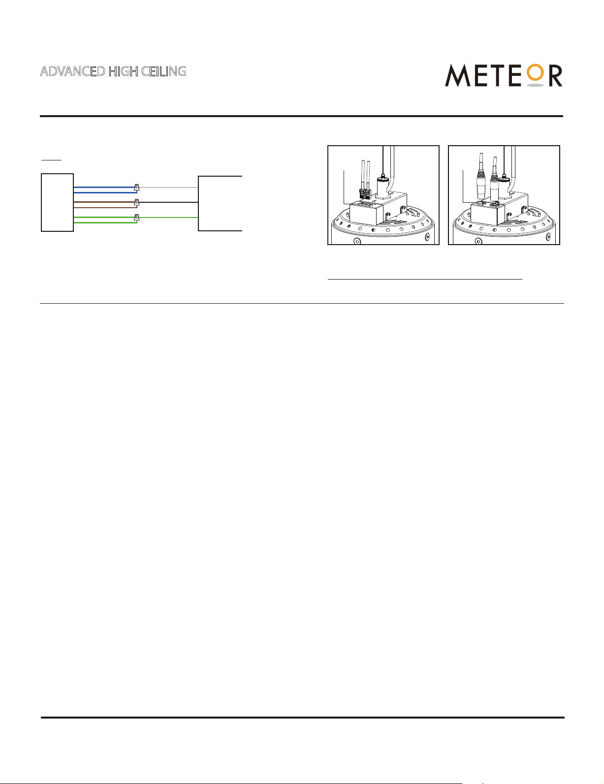
Wiring Diagram
DMX
Black(Line)
Green(Ground)
White(Neutral)
Brown(Line)
Green(Ground)
Blue(Neutral)
LED
Fixture AC Input
Connect DMX by using a standard DMX512 XLR cable
with 5 pin in/out connector (by others).
Connect DMX by using a standard shielded CAT5/6
cable.
*The last xture has to be terminated with a DMX Terminator (by others).
1. DMX is a digital three-wire system. Use all three!
2. DMX is based on the EIA-485/RS-485 standard.
3. Always use cable specically designed for DMX / RS-485. These cables have an impedance of 120Ω and a
low capacitance. For instance : Belden 9841 or 3105a.
4. DMX must be terminated with a 120Ω resistor to prevent reections.
5. A daisy chain topology should be used.
6. After 32 unit loads a repeater/booster should be used.
(Important : For tunable white xtures, After “32” unit loads a repeater/booster should be used.)
7. Keep cabling below 200 meters between the controller and the last driver.
8. It is generally considered good practice to provide separate DMX in and DMX out / DMX thru connections
to your xture to aid in installation. This can be in the form of pigtails, RJ-45 connectors or 5-pin XLR
connectors.
9. Use twisted pair cables with an impedance of 120Ω and a low capacitance.
10. UTP Cat5 or Cat6 network cable can also be used but have a slightly lower impedance of 100Ω.
11. If shielded cable is used, only connect shield to ground on one side (typically, the controller should have its
shield terminal connected to ground).
12. Not following the above recommendations may seem to work at rst, but can cause problems. Sometimes
after weeks of seemingly normal operation.
DMX/RDM is a robust and reliable system for lighting control. However, if not implemented correctly, problems can arise such as
random ashing of lights, erratic operation and delays in responding to commands. This document explains the best practices
in DMX wiring.
Application note : Wiring for DMX/RDM lighting systems
Important things to consider are:
XLR
DMX Box
RJ45
DMX Box
Page 5
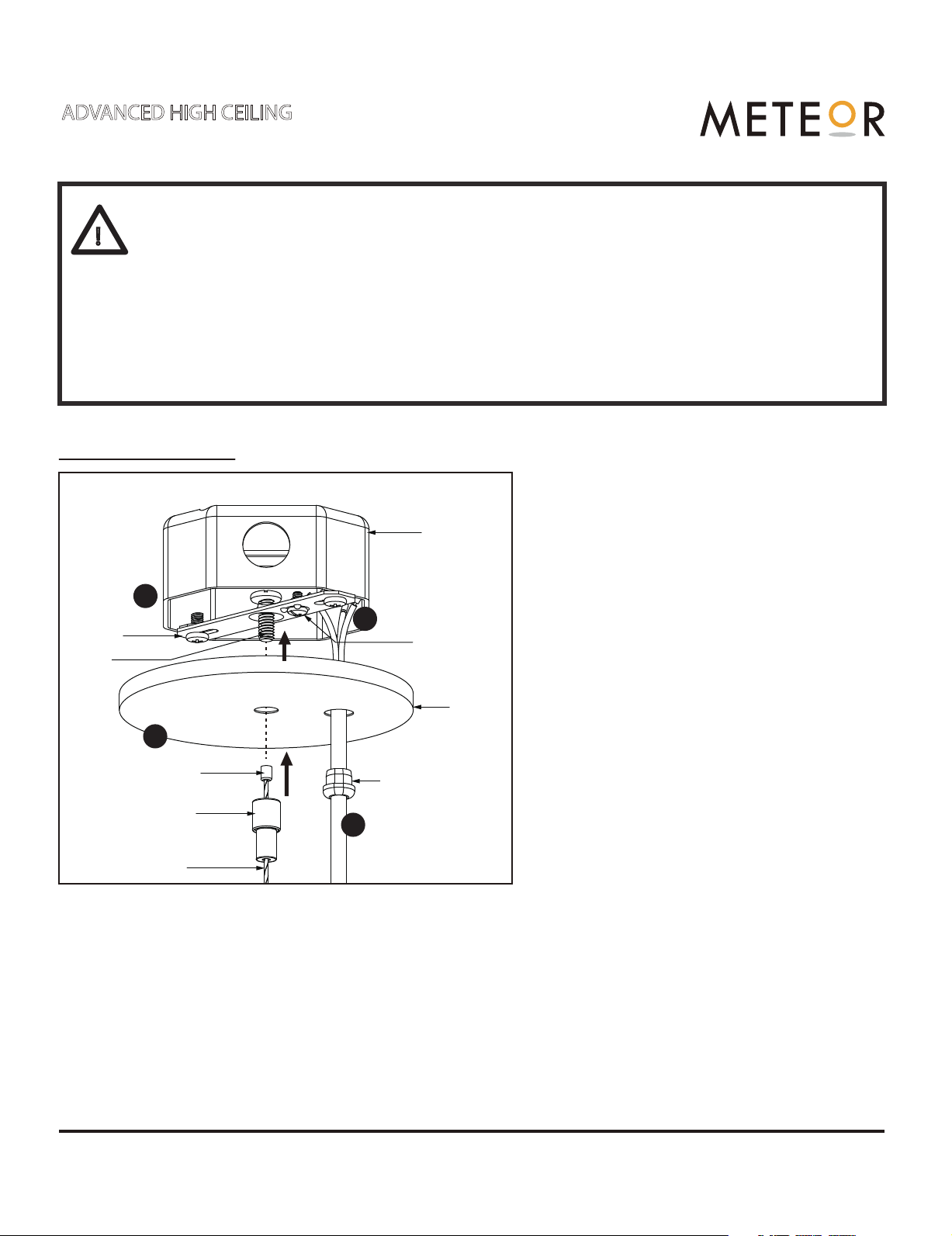
Installation Instructions
Atria 10 - Adjustable Cable
ADVANCED HIGH CEILING
METEOR LIGHTING P: 213.255.2060 F: 213.596.3704 www.meteor-lighting.com
*METEOR LIGHTING reserves the right to make changes to this product at any time without prior notice and such modication shall be eective immediately.