METER tensioLINK-USB Converter User manual
18221-01
11.2022
tensioLINK®
USB Converter
ãMETER Group AG München, 2022
INFIELD 7

2
1. Introduction
The tensioLINK-USB converter is used to connect sensors and
devices with serial
tensioLINK
interface to a PC. These sensors and
devices then can be configured, and readings can be uploaded or
taken online.
Sensors and devices with an 8-pin plug type M12 (e. g. T8) and a 4-pin
plug type can be connected to the converter directly.
The USB port provides the power supply.
The interface is controlled with the Windows software
tensioVIEW
.
TensioVIEW software is available on the METER website.
(https://meter.ly/environment-downloads-software).
1.1 Which sensors and devices can be connected?
Some of the sensors and devices with tensioLINK interface are:
- T8
- TEROS31, 32*
- Infield7b Handheld
- VS-2005 vacuum station
- HYPROP inc. adapter cable and T-piece
* M12 4-pin Version
1.2 What are the requirements?
- Windows PC with USB port (500 mA)
https://meter.ly/environment-downloads-software)
3
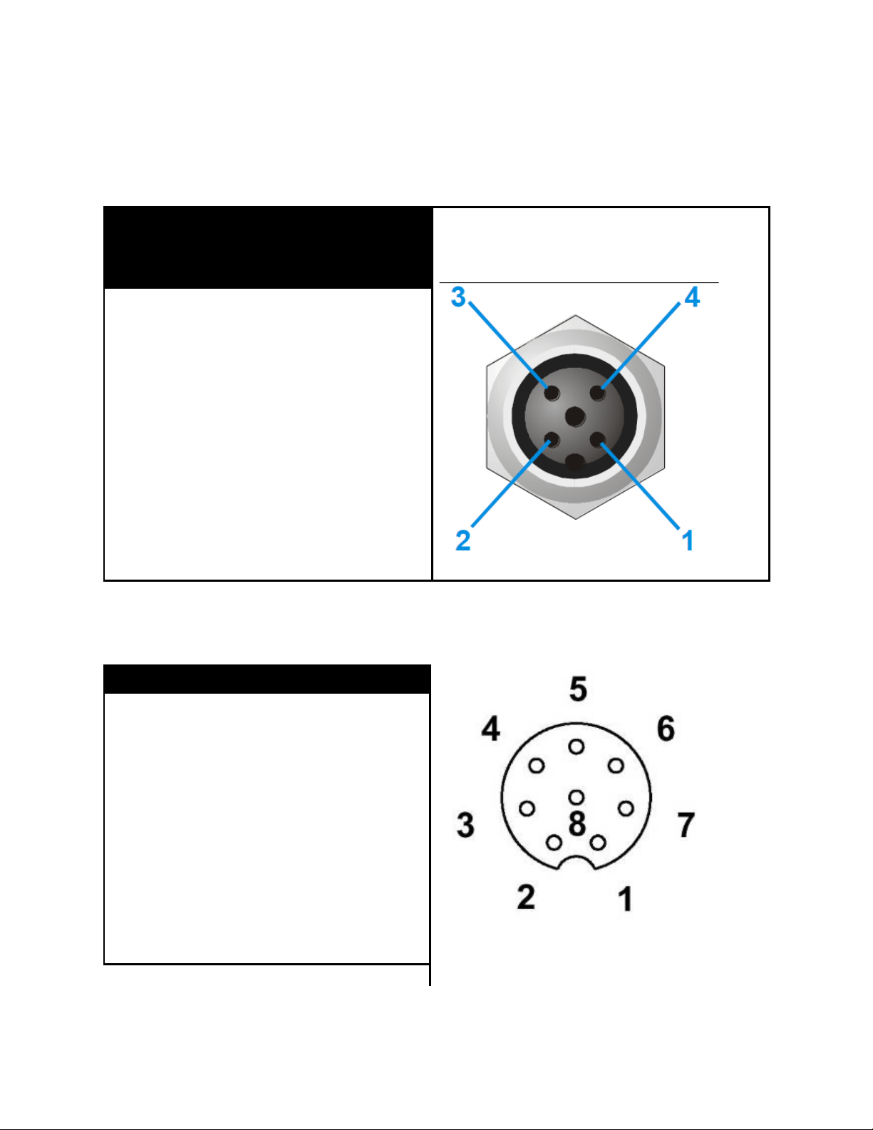
1.3 Plug configuration
4-pin M12 version:
Signal
Wire color
new
Function
PIN
V+
brown
6…20VDC
1
A
white
RS485-A
2
GND
blue
GND
3
B
black
RS485-B
4
8-pin M12 version:
Signal
Wire color
PIN
Female 8-pin plug
on USB converter
+9V/100mA
white
1
GND
brown
2
nc
green
3
nc
nc
RS485-A
RS485-B
nc
yellow
grey
pink
blue
red
4
5
6
7
8

4
To connect several sensors and devices at the same time distributor
boxes are available as an accessory.
If the current consumption of all connected sensors and devices
exceeds the capability of the USB port, the sensors and devices need to
be supplied by an external power supply. The GND of the external power
supply must be connected to the GND of the USB converter.
As standard not more than 5 sensors and devices should be supplied by
the USB converter at the same time.
Devices like the Infield7b or the VS-2005 have the capability to read
tensioLINK sensors themselves. These devices are equipped with a
female 8-pin plug. Connect them to the USB converter with the supplied
"host cable" (male to male plug).
With the host cable it is possible to get linked to the tensioLINK bus
directly on any free port of a distribution box. This means that sensor
communication is possible without separating them from the bus and
the power supply.
2. Installation
Follow the steps for installation described in the following sections.
2.1 INSTALLATION OF THE USB CONVERTER
Note: depending on the language of your Windows version the displayed messages might somehow be different.
1. Go to METER website and download the tensioVIEW software
(https://meter.ly/environment-downloads-software).
2. Connect the tensioLINK USB-converter to a suitable USB port. The
message that a new hardware is available should be displayed on
your desktop.

5
3. The hardware assistance will ask, “Search for software on this PC
or establish a connection to the Windows Update webpage for
searching for the software?” or a similar message.
• Select "NO, not this time,"
• Select Continue
4. In the next window select:
• "Install software automatically (recommended)"
• Select Continue
The software should be installed now.
NOTE: If a warning message like: "…. the hardware has not passed the Windows Logo Test …" or a
similar message appears, select, Continue installation.
The driver for the USB converter should now be installed successfully.
2.2 INSTALLATION OF TENSIOVIEW
Download the setup.exe file from the METER website software
downloads (https://meter.ly/environment-downloads-software).
Follow the instructions of the installation assistance.
3. Technical specifications
Sensor power supply: 9 VDC/100mA
Tolerance: ±1 V
Short circuit steadiness: 2 minutes
Galvanic isolation: 1 kV
Note: tensioLINK sensors require a power supply in the range of 6V to 20 VDC.
For the maximum number of sensors and devices that can be connected
at the same time consider the maximum power consumption of each
device, not the average consumption!
Serial sensor interface:
RS485 – 2 wire. Automatic switching TX-RX.
ESD protection: 15 kV (Human Body Model)
Galvanic isolation: 1 kV

6
USB interface:
USB 1.1 and 2.0 compatible. Only for USB ports with 500 mA maximum
output current.
Compliance:
A full CE declaration of conformity is available on request from METER
Group.
4. Customer Support
NORTH AMERICA
Contact our customer service representatives with questions, problems,
or feedback Monday through Friday, 7 am–5 pm Pacific time.
Email: [email protected]
Phone: +1.509.332.5984
Fax: +1.509.332.5158
Website: metergroup.com
EUROPE
Customer service representatives are available for questions, problems,
or feedback Monday through Friday, 8 am–5 pm Central European time.
Email: [email protected]
Phone: +49 89 12 66 52 0 OR +49 89 12 66 52 36
Fax: +49 89 12 66 52 20
Website: metergroup.de
7
If contacting METER by email, please include the following information:
Name
Address
Phone
Email address
Instrument serial number
Description of the problem
NOTE: For products purchased through a distributor, please contact the distributor
directly for assistance.
4.1 TERMS AND CONDITIONS
By using METER instruments and documentation, you
agree to abide by the METER Group, Inc. USA Terms
and Conditions. Please refer to
metergroup.com/terms-conditionsfor details.
Table of contents
Popular Media Converter manuals by other brands


H&B
H&B TX-100 Installation and instruction manual

Bolin Technology
Bolin Technology D Series user manual

IFM Electronic
IFM Electronic Efector 400 RN30 Series Device manual

GRASS VALLEY
GRASS VALLEY KUDOSPRO ULC2000 user manual

Linear Technology
Linear Technology DC1523A Demo Manual

Lika
Lika ROTAPULS I28 Series quick start guide

Weidmuller
Weidmuller IE-MC-VL Series Hardware installation guide

Optical Systems Design
Optical Systems Design OSD2139 Series Operator's manual

Tema Telecomunicazioni
Tema Telecomunicazioni AD615/S product manual

KTI Networks
KTI Networks KGC-352 Series installation guide

Gira
Gira 0588 Series operating instructions

Lika
Lika SFA-5000-FD user guide