metex PRO MILL E3 User manual

OPER
MILL E3
ATOR’S MANUAL


1
NOTE
The information contained in this handbook is intended as a guide to the operation of these machines and
does not form part of any contract. The data it contains has been obtained from the machine
manufacturer and from other sources. Whilst every effort has been made to ensure the accuracy of these
transcriptions it would be impracticable to verify each and every item. Furthermore, development of the
machine may mean that the equipment supplied may differ in detail from the descriptions herein. The
responsibility therefore lies with the user to satisfy himself that the equipment or process described is
suitable for the purpose intended.
LIMITED WARRANTY
We Makes every effort to assure that its products meet high quality and durability standards and
warrants to the original retail consumer/purchaser of our products that each product be free from defects
in materials and workmanship as follow: ONE YEAR LIMITED WARRANTY ON ALL PRODUCTS UNLESSSPEClFIED
OTHERWISE. This Warranty does not apply to defects due directly or indirectly to misuse, abuse,
negligence or accidents, normal wear-and tear, repair or alterations outside our facilities, or to a lack of
maintenance.
We shall in no event be liable for death, injuries to persons or property or for incidental, contingent,
special, or consequential damages arising from the use of our products.
The manufacturers reserve the right to change specifications at any time as they continually strive to
achieve better quality equipment.
To take advantage of this warranty, the product or part must be returned to us for examination, postage
prepaid. Proof of purchase date and an explanation of the complaint must accompany the merchandise. If
our inspection discloses a defect, we will either repair or replace the product, or refund the purchases
price if we cannot readily and quickly provide a repair or replacement, if you are willing to accept a refund.
We will return repaired product or replacement at our expense, but if it is determined there in no
defect, or that the defect resulted from causes not within the scope of our's warranty, then the user
must bear the cost of storing and returning the product.
Copyright. The copyright of this instruction book is the property of us and may not be reproduced or
copied without prior consent of us.

2
WARNING!
Read and understand the entire instruction
manual before attempting set-up or
operation of this mill/drill
1. This machine is designed and intended for use
by properly trained and experienced personnel
only. If you are not familiar with the proper safe use
of mill/drills, do not use this machine until proper
Training and knowledge has been obtained.
2. Keep guards in place. Safety guards must
be kept in place and in working order.
3. Remover adjusting keys and wrenches. Before
turning on machine, check to see that any adjusting
wrenches are removed from the tool.
4. Reduce the risk of unintentional starting.
Make sure switch is in the OFF position before
plugging in the tool.
5. Do not force tools. Always use a tool at the rate
for which it was designed.
6. Use the right tool. Do not force a tool or
attachment do a job for which it was not designed.
7. Maintain tools with care. Keep tools sharp and
clean for best and safest performance. Follow
instructions for lubrication and changing accessories.
8. Always disconnect the tools from the power
Source before adjusting or servicing.
9. Check for damaged parts. Check for alignment of
moving pads, breakage of parts, mounting, and any
Other condition that may affect the tools operation.
10. Turn power off, Never leave a tool unattended,
Do not leave a tool until it comes to a complete stop.
11. Keep work area clean, Cluttered areas and bench
Invite accidents.
12. Do not use in a dangerous environment, Do not
Use power tools in damp or wet locations, or expose
Them to rain. Keep work area well lighted.
13. Keep children and visitors away. All visitors
should be kept a safe distance from the work area
14. Make the workshop child proof. Use padlocks,
. master switches and remove starter keys.
15. Wear proper apparel. Loose clothing, gloves,
neckties, rings, bracelets, or other jewelry may
get caught in moving parts. Non-slip footwear
is recommended. Wear protective hair covering
to contain long hair. Do not wear any glove.
16. Always use safety glasses. Also use face or
dust mask if cutting operation is dusty.
Everyday eyeglasses only have impact
resistant lenses, they are not safety glasses.
accessories may be hazardous.
17 Do not overreach. Keep proper footing and
balance at all times.
18. Do not place hands near the cutterhead
while the machine is operating.
19. Do not perform any set-up work while
machine is operating.
20. Read and understand all warnings posted
on the machine.
21 This manual is intended to familiarize you with
the technical aspects of this mill/drill. It is not,
nor was it intended to be, a training manual.
22. Failure to comply with all of theses warnings
may result in serious injury.
23. Some dust created by power sanding, sawing,
grinding, drilling and other construction act/rites
contains chemicals known to cause cancer, birth
defects or other reproductive harm.
24. Your risk from those exposures varies,
depending on how often you do this type of work.
To reduce your exposure to these chemicals,
work in a well ventilated are, and work with
approved safety equipment

3
MATN TECHNZCAL SPECZFTCATTON
SPECCIFICATION
The specifications in this manual are given as general information and are not binding. We reserves
the right to effect, at any time and without prior notice, changes or alterations to parts, fitting and
accessory equipment deemed necessary for any reason whatsoever.
Drilling Capacity ................................................................................................ 32mm
End Mill Capacity .............................................................................................. 20mm
Face Mill Capacity ............................................................................................. 76mm
Spindle Taper ................................................................................................... ISO30
Spindle Stroke ................................................................................................. 95mm
Head Tilt ............................................................................................................ ±90°
Number of Spindle Speeds ............................................................................ Variable
Ranger of Spindle Speeds .......................................................................... 100-2500 RPM
Working Surface of Table ............................................................................... 700X210 mm
Max. Table longitudinal Travel ........................................................................ 500mm
Max. Table Cross Travel ................................................................................. 200mm
Max. vertical travel ......................................................................................... 310mm
Number of T-Slots .............................................................................................. 3
T-Slot Size ..................................................................................................... 14 mm
Brushless Motor ......................................................................................... 1.5KW, IPh, 240V
Overall Dimensions ................................................................................. 900x740x1150 mm
Net Weight(approx.) ......................................................................................... 220KGS
Shipping Weight (approx.) ................................................................................. 240KGS

4
WARRANTY ................................................................................................................. 1
WARNINGS .................................................................................................................. 2
SPECIFICATIONS ........................................................................................................ 3
TABLE OF CONTENTS ................................................................................................ 4
CONTENTS OF SHIPPING CONTAINER .................................................................... 5
UNPACKING AND CLEAN-UP ..................................................................................... 5
ASSEMBLY ................................................................................................................... 6
INSTALLATION ............................................................................................................. 6
CONTROLS ................................................................................................................ 7 - 8
ELECTRICAL CONNECTIONS .................................................................................... 9
ARBOR REPLACE ....................................................................................................... 10
GIB ADJUSTMENT ...................................................................................................... 11
MAINTENANCE ........................................................................................................... 12
TROUBLE SOLUTION ................................................................................................. 12
TABLE OF CONTENTS
Read and understand the entire contents of this
Manual before attempting set-up or operation!
Failure to comply may cause serious injure!
WARNING
1 MILL E3
1 Drawbar (installed on machine)
1 Digital scale & Speed Readout
1 Test Flow Chart
1 Operator Manual
1 Toolbox & Tools
CONTENTS OF SHIPPING CONTAINER
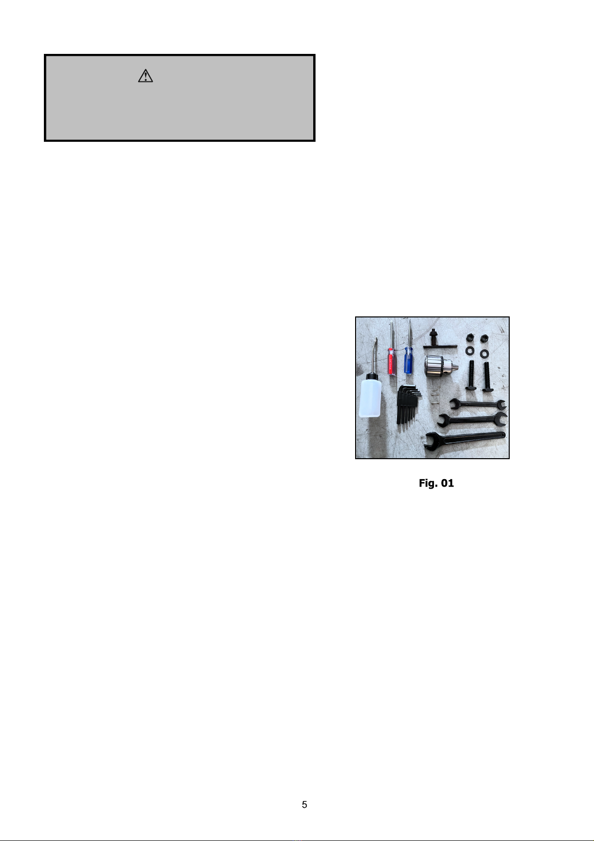
Toolbox Contents (Fig.01)
1 Oil Gun
2 Fuse (15A)
1 Single End Spanner (24mm)
2 Double End Spanner (12-14mm,17-19mm)
6 Hex Socket Wrench (2.5,3,4,5,6,8mm)
1 Drill Chuck with Key
1 Flat Blade Screwdriver
1 Cross Blade Screwdriver
2 M12 “T” Screw
2 M12 Washer
2 M12 Nut
Unpacking and Clean-up
1. Finish removing the wooden crate from around
the mill/drill.
2. Unbolt the machine from the crate bottom.
3. Sling mill/drill with the proper equipment.
4. Clean all rust protected surfaces using a mild
commercial solvent, kerosene or diesel fuel. Do not
use paint thinne , gasoline, or lacquer thinner.
These will damage painted surfaces. Cover all
cleaned surfaces with a light film of machine oil.
1 Drill Chuck Arbor ISO3 (installed on machine))0-JT6
66
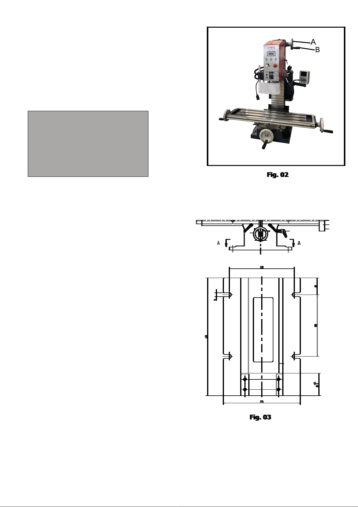
Assembly
1. Screw handles (A, Fig.02) onto handwheel (B,
Fig.3) and tighten.
2. Repeat for remaining handles of table.
Installation
Machine is heavy! Use an appropriate lifting
device and use extreme caution when moving the
machine to its final location.
Failure to comply may cause serious injury!
WARNING!
1. The location for the mill/drill should be well lit, dry,
and have room enough to allow the head to
rotate 360°.
2. Carefully lift the mill/drill with properly rated
equipment to a sturdy stand or working bench.
For best performance, through bolt the mill/drill to
a stand.
We do not recommend that unattached machines be
operated, as the machine will move during
operation!
3. Before bolting the mill/drill to a bench or stand,
the unit must be level in both directions. Place a
level on the table in both directions.
4. If the table of mill is not to level, shim under the
Iow corner(s) until level. Tighten the fastening
bolts. Check for level again. Adjust as necessary
until the mill/drill is level. Check again when
securing bolts are tightened.
Installation Drawing (Fig. 03)
The installation drawing described below may differ
from the real dimensions. The tolerances are in the
range of the general tolerances according to DIN
7168.
7
CONTROL
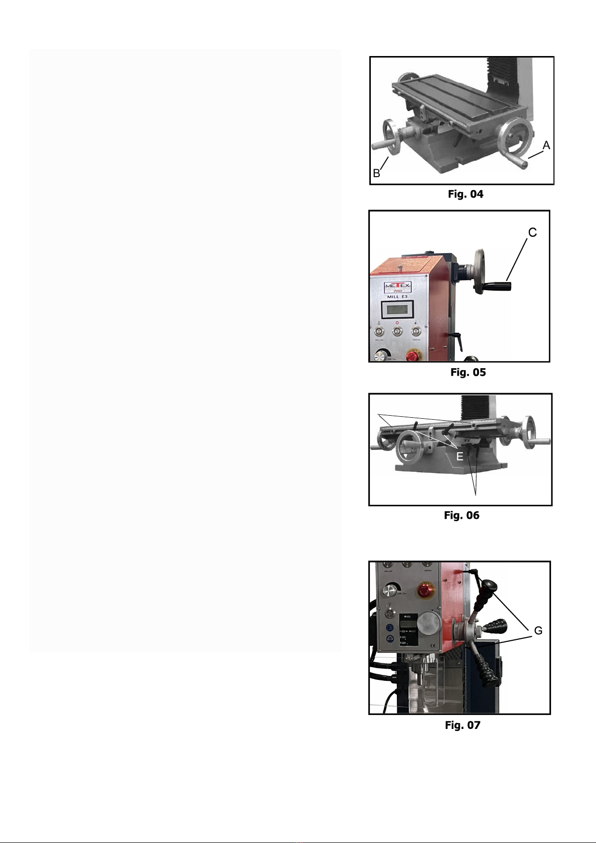
Longitudinal Handwheel (A, Fig. 04)
Located on two side of the table. Moves table side to
side.
Cross Feed Handwheel (B, Fig. 04)
Located on the front of the base. Moves table toward,
or away from the column.
Head Elevating handwheel (C, Fig.05),
Locate on the right of column. The head can be
adjusted up or down to suit height requirements for
different workpieces. Turn it clockwise to up head on
the column and counter-clockwise to down. When the
head is at the desired height, lock in place with the
locks
.
Caution: Have to loosen the locks for the slideways
before above operation!
Adjustable Table Stops (D, Fig.06)
Located on table front. Adjust to stop table at any
setting along the longitudinal axis.
Table locks
Longitudinal table locks (E, Fig. 06) are located on
front of the table. Cross-feed table locks (F, Fig.05)
are located on the right side under the table. Turn
clockwise to lock the slideways.
Mill Head locks (G, Fig.07)
Located on the right of column. Turn clockwise to lock
the mill head.
Quill Lock Lever (H, Fig. 07)
Located on the left of the mill head. The height of the
spindle can be locked with the quill lock lever. Set the
desired height with the quill lever and turn the lever
down. Turn clockwise to lock the quill, reverse to
loosen.
Caution: For best results. All milling operations
should be done with the quill/spindle as close to
the head assembly as possible. Lock spindle, table
and mill head in place before starting milling
operations!
8
MJ
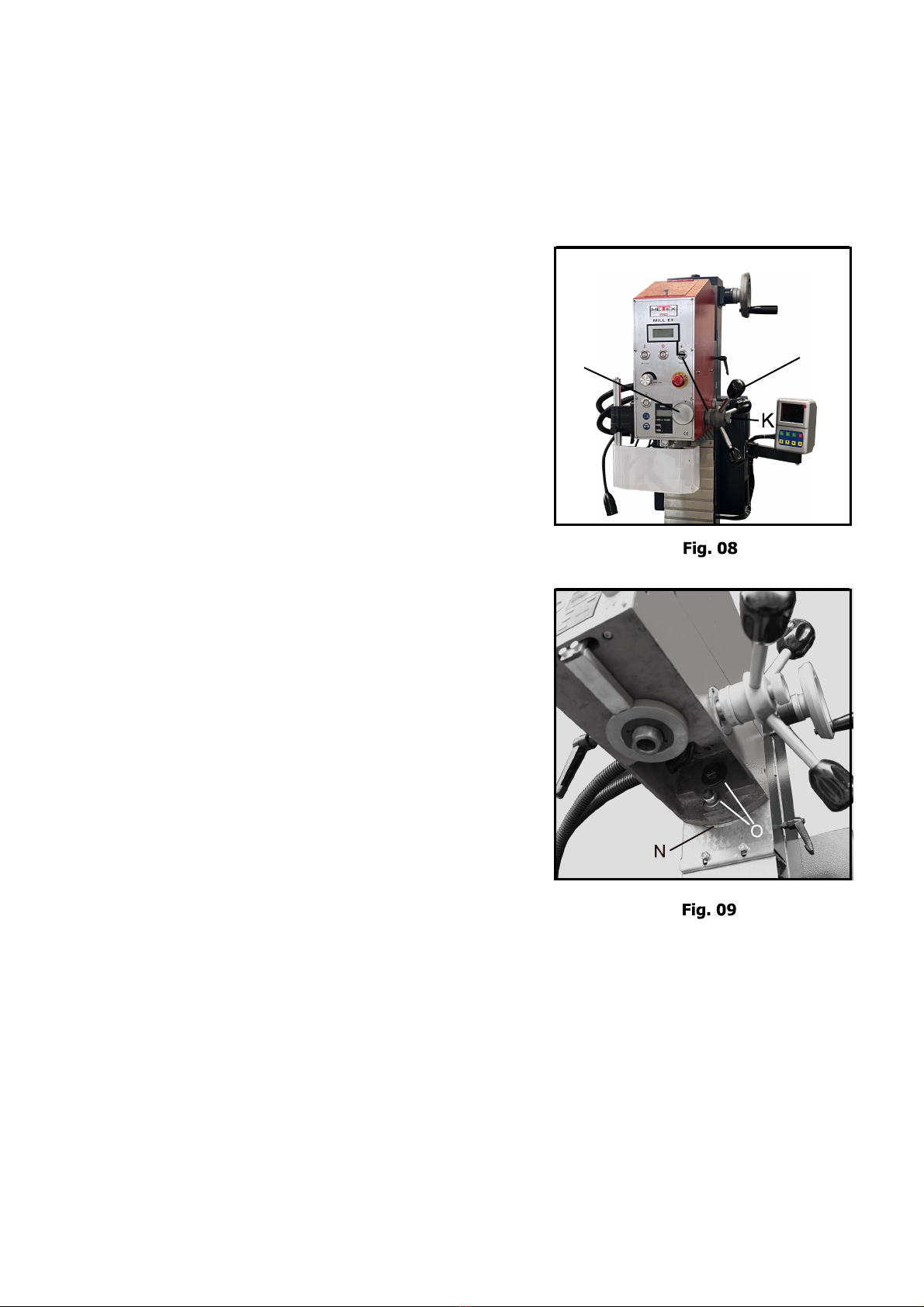
Down feed Handles: (J, Fig. 08):
Located on the right side of the head casting.
Counter-clockwise movement advances the quill
toward the table. Return spring retracts the handles.
The knob (K, Fig. 08) must be loose before the
operating the handles. The graduated dials (L, Fig.
08) on the handle base can be indexed or "zeroed" to
help make accurate and convenient movements.
Fine Down Feed
Turn counter-clockwise the knob (K, Fig. 08) to
engage the fine down feed knob (M, Fig. 08) what
located on the front of the head. Turn it according to
you want to move downward, Clockwise turn the
hand wheel to down feed the spindle, reverse to
retract it.
Mill Head Rotation
The head is designed to tilt 90° either left or right,
enabling it to perform task such as angle drilling or
horizontal slotting. Loosen the lock nuts (N, Fig. 09)
under the head. Rotate the head to its desired
position, using the reference guide (O, Fig.09). Once
in place, re-tighten the lock nuts.
Note: make sure to provide support for the head
so it doesn't unexpectedly rotate on its own.
Always maintain control of the head.
Caution: Even at Iow spindle speeds, metal
fragments from the cutting process can be expelled
by the mill/drill. Always wear eyewear and
protective clothing when operating the machine!
9
94BL-7550 1.1KW
Brushless Motor
3 25 5.2
E
R
A
B
L
( E,
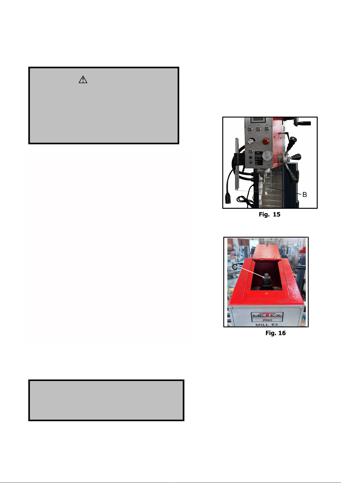
Emergency Stop Switch (A, Fig.12) Depress to stop
all machine functions. Twist to re-rest.
Work light switch ( L, Fig.12 ) Press once to turn on
the work light, press again to turn off the work light.
Power switch ( R, Fig.12 )
3
M
1
TC1 TC2
AC24V/10A
3
24
1 1 3 8 1
0V
KA2 FWD FWD
REV
COM
2
3
1 1 2 2 2 83
Working lamp
36
Speedometer
0V
0V
W
1V 1U1W
W1 U1 PE
M1
bla
blu gre yel
red
750W / 1.1KW
Spindle
Sensor
V1
blue yellow green
U V
5V
5V
34
1
6
6 5
NL
L
1AC230V
N PE
N1L1
1
2
3
4
QS1
7 3 4
KA3
KA2X1X1 SQ1 XT1XT1
KA1
KA3
SB4
8
1
1
4
COM
REV
0V A B C 5V
IVA V5
46 7
6
28
5
22 25
26 30 32
6 7
4
SB1 SQ1 SB3 KA3 KA1 A1
R1
L
N
KA1
SB2
KA1 L2
N1
KA3
0
2
3 4
3 4
1
AC24V/10A
3 4
2
SB5
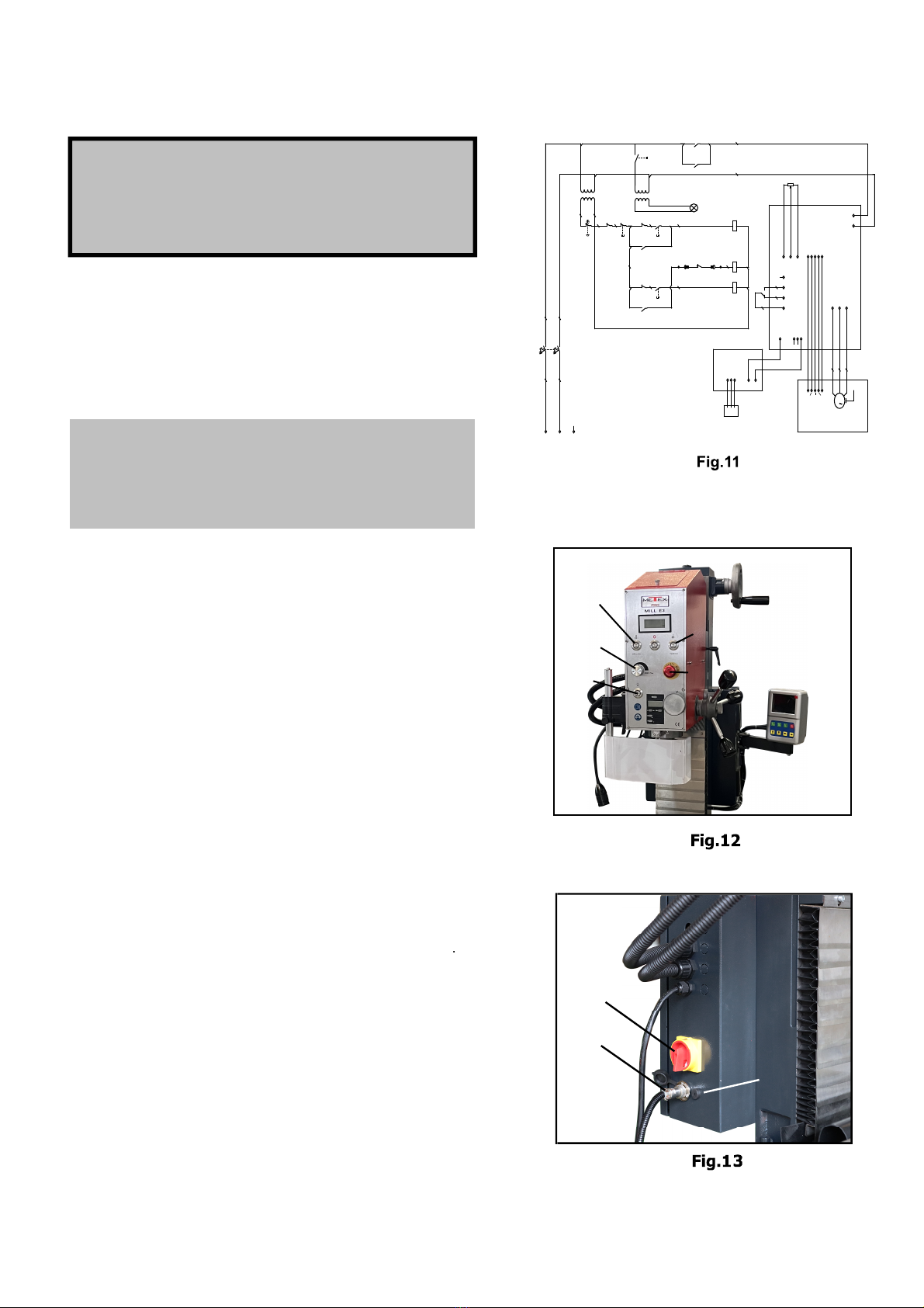
ELECTRICAL CONNECTIONS
WARNING!
Make sure the machine is properly ground!
Failure to do so may cause serious injury and
damage to user!
WARNING!
A qualified electrician must make all electrical
connections!
Failure to do so may cause serious injury!
Before connecting the machine to the mains, make sure
that the electrical values of the mains supply are the
same as those for the machine's electrical components.
Use the wiring diagram (Fig. 11) for connecting the lathe
to the mains supply.
Work light switch ( F, Fig.12 ) Press once to turn on
the work light, press again to turn off the work light.
Brushless Motor
its type is 94BL-7550, 230V, 2500rpm, 5.2A, 1.1 KW
Work light switch ( F, Fig.12 ) Press once to turn on
the work light, press again to turn off the work light
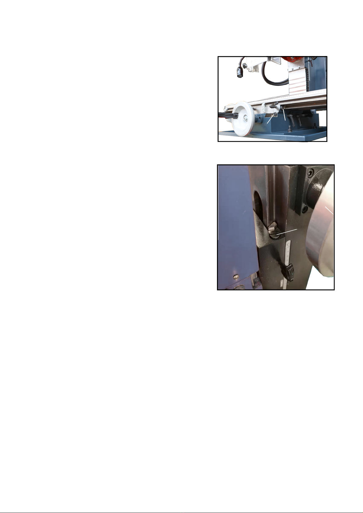
Foot Switch (H, Fig.13) (Optional for tapping function)
Remove the parts from the aviation socket, plug the foot
switch(optional). Depress the reverse switch, the spindle
will rotate in reverse direction, then step on the foot switch
for tapping and release for return.
Main power switch (P, Fig.13)
Make sure that all 2 phase (L&N) are connected
Forward Switch (B, Fig. 12) Depress to start the spindle
rotate in forward direction.
Reverse Switch (C, Fig. 12) Depress to start the spindle
rotate in reverse direction.
Emergency Stop Switch (D, Fig.12) Depress to stop
all machine functions. Twist to re-rest.
Potentiometer (E, Fig. 12) Turn clockwise to increase the
spindle speed and count-clockwise to decrease. Always
start the machine with the potentiometer knob set at Zero.
Fuse holder (G, Fig. 13) Located on the of electric box
Left side. Fuse rated at 10A. Open to change the fuse if
necessary.
Spindle on/off switch (A, Figure 12). Depress to connect
the power supply to the machine. When the spindle is
working, press the switch again to stop the rotation.
G
H
P
2.
1.
3.
4.
5.
6.
10
This machine is designed and intended for use by
properly trained and experienced personnel only! Zf
you are not familiar with the proper and safe use of
mill/drills, don't use the machine until proper
training and knowledge have been obtained!
Failure to comply may cause serious injury!
WARNING!
Arbor Replacement
1. Disconnect machine from the power source,
unplug.
2. Hold the flat of spindle (B, Fig.15) to keep it from
moving while loosening the drawbar (C, Fig 16)
with the 22-25 spanner in toolbox.
3. Loosen the drawbar approximately three to four
full turns.
4. Tap the drawbar head with a rubber mallet to
dislodge the arbor.
5. Grasp the arbor with on hand while loosening the
drawbar with the other. Continue to loosen the
drawbar until the arbor can be withdrawn from
the spindle. Wipe out the spindle with a clean dry
rag.
6. Wipe down the new arbor with a clean dry rag
and place the arbor into the spindle. Thread the
drawbar into the arbor. Tighten the drawbar with
a spanner while holding the spindle.
WARNING!
Do not loosen the drawbar more than three or
four turns before hitting with a rubber mallet.
Damage to the drawbar threads may occur!
11
A
B
Fig. 17
C
Fig. 18
GIBS ADJUSTMENT
After a period of time, movement of the table over the
ways will cause normal wear. Adjust the gibs to
compensate for this wear.
1. The horizontal gib adjustment screw (A, Fig.17) is
found to the rear right on table. The traverse gib
adjustment screw (B, Fig.17) is found on the right
side of saddle under the table. The vertical gib
adjustment screw (C, Fig.18) is found onto the
column.
2. Loose the screw from small taper end of gib. Turn
the screw from large taper end of gib slightly
clockwise to tighten. Turn the table handwheel and
check the tension.
3. Re-adjust as required.

12
Solution
Readjust gibs
Lock all axes but the one moving
Lock mill head
Tighten quill lock
Center tool
reshape, sharpen, or replace tool
Lock quill
Make sure setup is parallel to table
Use sharp bits
Remount tool
Remount chuck on arbor
Tighten drawbar
Tighten or replace bearings
Reduce speed
Reduce feed rate
Apply lubricant
Clean chuck
Clean arbor and remount
Clean spindle and replace drawbar
Plug in machine
Tighten wiring connections
Maintenance
Keep the maintenance of the machine tool during the operation to guarantee the accuracy and
service life of the machine.
1. In order to retain the machine's precision and functionality, it is essential to treat it with care, keep
it clean and grease and lubricate it regularly. Only through good care, you can be sure that the
working quality of the machine will remain constant. Disconnect the machine plug from the
mains supply whenever you carry out cleaning, maintenance or repair work!
2. Lubrication all slideways lightly before every use. The leadscrew must also be lightly lubricated
with lithium base grease.
3. During the operation, the chips what falls onto the sliding surface should be cleaned timely, and
the inspection should be often made to prevent chips falling into sliding ways. Asphalt felt should
be cleaned at certain time. Do not remove the chips with your bare hands. There is a risk of
cuts due to sharp-edged chips.
4. After the operation every day, eliminate all the chips and clean different part of the machine and
apply machine oil to prevent rusting.
5. In order to maintain the machining accuracy, take care of the arbor, drawbar, the surface of the
worktable and the guide way and avoid mechanical damage and the wear due to improper guide.
6. If the damage is found, the maintenance should be done immediately.
Trouble Solution
Problem
Too chatters
Possible Cause
Gibs too loose on table, column
Unused feeds not locked
Mill head not locked
Quill too loose
Tool not on center
Improper tool shape, tool dull
Quill moving
Setup wrong
Bit dull
Bit not mounted correctly in chuck
Chuck loose in spindle
Drawbar not secured
Bearing loosen or worn
Cutting too fast
Bit fed into work too fast
Chuck sticking
Debris in chuck
Chuck loose on arbor
Drawbar not tight
Machine unplugged
Loose electrical connections
Depth of cut is not consistent
Hole is off center or bit wanders
Bit turns erratically or stops
Chuck is difficult to tighten or loosen
Chuck wobbles
Turn on machine and nothing happer

PART LIST
MILL E3

214 215
205
205
216
217
218
219
220
201 202 203
204
221
222
223
224
225
226
227
228
229
230
231
232
233 234
235
237
236
259
260
238
239
240
241
242
243
244
245
246
247
248
249
250
251
252
253
225
210
211
212
213
206
255
207
208
209
1
205
123
254
258 257
247
256

Parts No. Descrip tion Specific ation Qty
201
202
203
204
205
206
207
208
209
210
211
212
213
214
215
216
217
218
219
220
221
222
223
224
225
226
227
228
229
230
231
232
233
234
235
236
237
238
1
1
1
7
4
4
4
4
4
4
1
1
1
1
1
2
1
1
1
1
1
1
1
1
1
1
5
1
1
1
1
1
1
1
2
1
8
2
”8/3gulP
Drawbar Cover
Motor Cover
Washer4
Hex Head Cap Screw M4×8
Round head Phillips screw M5×16
Spring washer
Washer
Hex Head Cap Screw M8×2
8
8
0
Spring washer
Washer
Washer
MBrushless otor 1.5KW
Mill Head
Locking Lever M8×20
Brass Pin
Bracket
Digital Scale
Hex Head Cap Screw M4×60
Base
Hex Head Cap Screw M3×8
Label
Knob
Set Screw M5×10
Spring Piece
Dial
Worm Shaft
Bearing 7007
7006
Sleeve
Rubber Ring
Bearing
Adjusted Nut
Hex Head Cap Screw M5×12
03×6niP
Pin 5×12
Spindle
Ring
Retainer cup
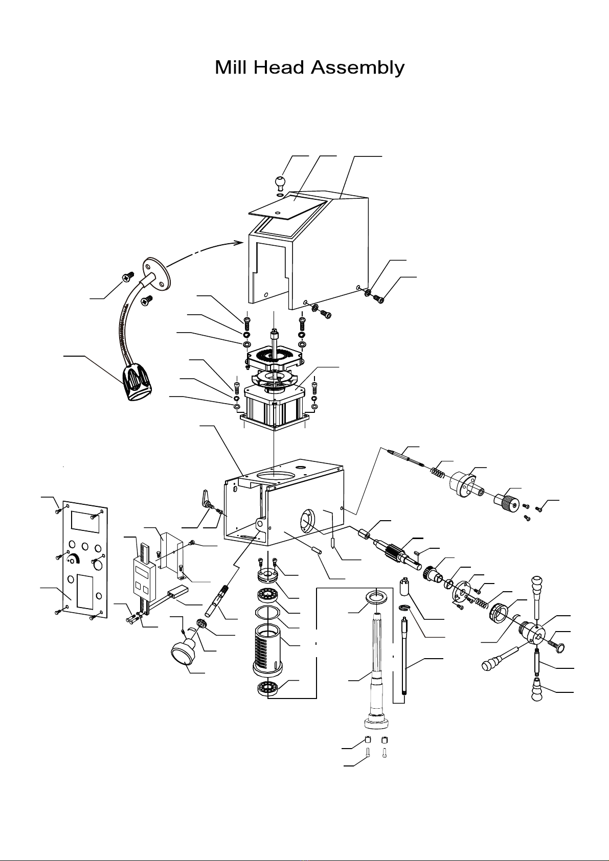
MILL HEAD ASSEMBLY

Position Washer239
1042
1
1
3142
3242
243
1442
1
1
1
1
1
1
1
1
1
1
2
1
1
245
246
247
248
249
250
251
252
253
254
255
256
257
25
259
260
Stopper 2
2
8
3
Drawbar
Handle
Handle Lever
Locking Knob
Base
Dial
Spring
Hex Head Cap Screw M4×12 3
Flange
Washer
Worm Gear
Gear shaft
Key 6×16
Block
Screw
MILL HEAD ASSEMBLY
Work Lamp
Compression spring
Locking pin seat
Locking pin sleeve
He M6×16x Head Cap Screw
21
72
7315
62
63
42
64 48
75
74
42
64
48
67
68
66
65
58
54
59
17
53
52
46 46
47
48
45
44
3
43
42
41403938
32
40
50
12
21
17
16
14 15
29
30
31
32
33
34
21
35
36
437
17
13
18
4
7
27
28
11
20
84
21
22
23
24
26 25
10
19
9
16
17
56
55
57
575860
7170
71 18
76 84
73
85
7714
78
66
83
18
7
61
7963
4262
44
45 3
82
81
80
57
79
49
51
69
3
44
48
17 16
17
16
45
73
45
4
Table of contents
Popular Industrial Equipment manuals by other brands

GFA
GFA ELEKTROMAT KE 40.24-40,00 installation instructions

Clarke
Clarke CPT250 Operating and maintenance instructions

Siemens
Siemens 3RT7014 Series operating instructions

Ultraflex
Ultraflex X72 installation manual

SMC Networks
SMC Networks MHZ2-6 Series operating manual

Tescom
Tescom 44-3200 Instructions for use


