Mounting instructions (Original: de)
8031363
1411NH
†‡
Swivel flange
DAMS-K-V1-...-V-R3
Festo AG & Co. KG
Postfach
73726 Esslingen
Germany
+49 711 347-0
www.festo.com
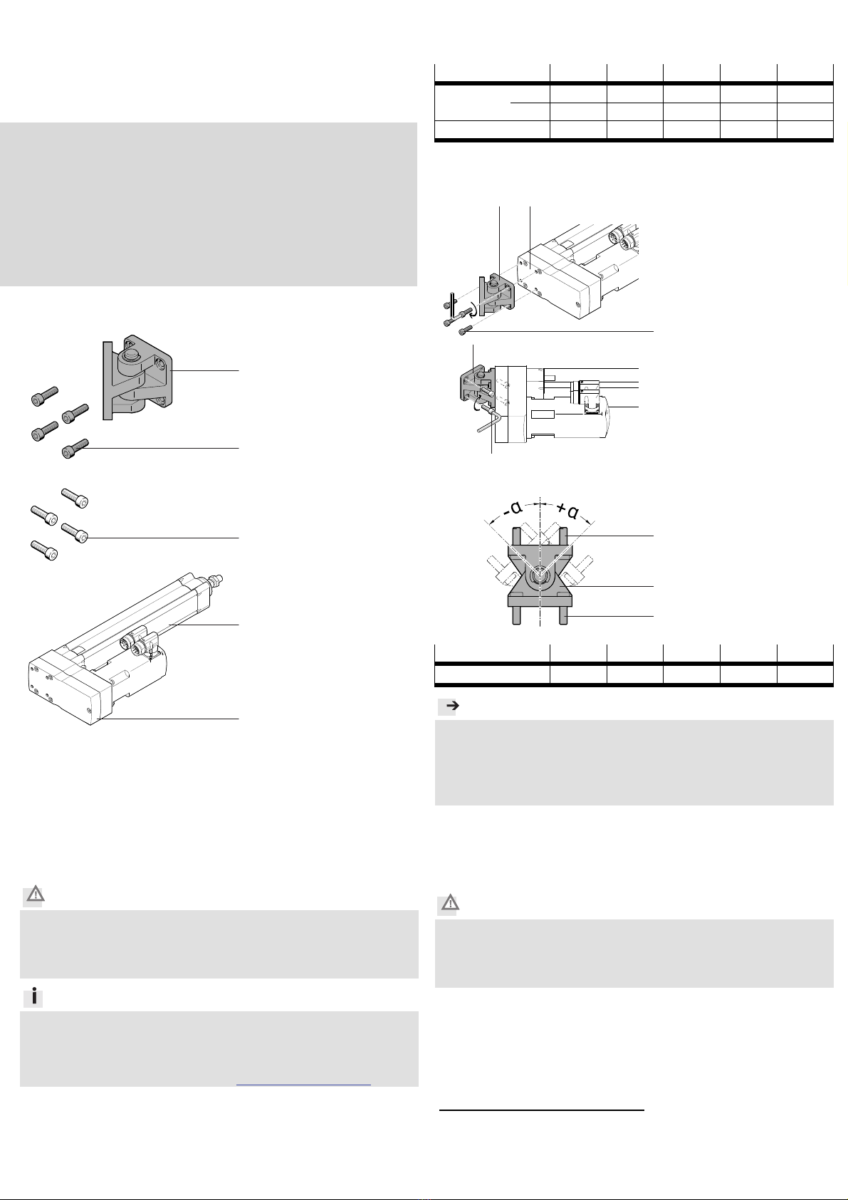
1. Parts list
21107d_1
1Swivel flange
2Screw
(1x)
(4x)
Not included in delivery:
21107d_3
3Screw (4x)
21107d_2
4Electric cylinder
ESBF
5Parallel kit
EAMM-U
(1x)
(1x)
2. Intended use
Swivel flange DAMS-K-V1-...-V-R3:
Swivel mounting of the electric cylinder 4on parallel kit 5.
The swivel flange is designed for the higher loading forces of the electric
cylinder 4.
3. Safety instructions and notes on mounting
Caution
Unexpected movement of components.
Injury due to impacts or pinching.
Switch off power supply before mounting work.
Observe the safety instructions (applicable documents).
Information
Applicable documents
operating instructions for the electric cylinder 4
mounting instructions for the parallel kit 5
Accessories for the electric cylinder 4www.festo.com/catalogue
4. Screw sizes and tightening torques MA
1)
DAMS-K-V1-...-V-R3 40 50 63 80 100
2
Screw M6x20 M8x25 M8x25 M10x30 M10x30
[Nm] 6 14 14 27 27
3
Screw M6 M8 M8 M10 M10
Select screws 3suitable for the installation situation.
5. Mounting
21107d_4
Place the swivel flange 1
on the parallel kit 5
depending on the required
swivel direction.
Tighten screws 2. Comply
with the tightening torque
(section 4).
21107d_5
Secure the swivel flange 1
to the mounting surface by
using the screws 3.
6. Maximum swivel angle á2)
21107d_6
DAMS-K-V1-...-V-R3 40 50 63 80 100
Swivel angle á3
±32° ±45° ±42° ±31° ±36°
Note
Limitations of the swivel angle are caused by the overall structure of the
system.
Collision of components, e.g. parallel kit 5with the mounting surface.
Prior to commissioning:
Check the possible swivel angle of all moving components.
7. Maintenance
The swivel flange DAMS-...-40/-50/-63/-80 is maintenance-free.
When using swivel flange DAMS-...-100:
Caution
Breaking of the swivel flange 1. Unexpected movement of components.
Injury due to electric shock, impact, squeezing.
Replace electric cylinder 4and swivel flange 1at the same time.
The service life of the components is comparable with one another.
1) Tolerance for tightening torques MAwithout indication of tolerance ± 10 %
2) Maximum swivel angle applies for screws 2/3according to DIN EN ISO 4762:2004-06
and DIN 912:1983-12.
3) Tolerance for á± 1°


