Metkon METACUT 302 Administrator Guide

1
metkon.com
OPERATION & INSTRUCTION MANUAL
ABRASIVE CUTTING

2
EC Declaration of Conformity
Manufacturer : Metkon Instruments Inc.
Address : Demirtas Dumlupinar Organize Sanayi Bolgesi
Ali Osman Sonmez Cd. No: 14 Bursa / TURKEY
Model No : METACUT 302
Herewith declares that;
Metallographic Cutting Machine
is in conformity with the provisions of the Machinery Directive (directive 2006/42/EEC), as amended, and with national
implementing legislation;
is in conformity with the provisions of the Low Voltage Directive (directive 2014/35/EU), as amended, and with national
implementing legislation;
is in conformity with the provisions of the EMC Directive (directive 2014/30/EU), as amended, and with national
implementing legislation;
And furthermore declares that
the following (parts/clauses of) standards have been applied
EN ISO 12100:2010, TS EN 60204-1, TS EN IEC 61000-6-2, TS EN 61000-6-4
Authorized Person: ERCIN SENAY
Position: Manager of Research and Development Department
Year: 2019
Bursa / Turkey

3
Index
DESCRIPTION ............................................................................................................................ 5
Design .....................................................................................................................................................................................5
Technical Data ........................................................................................................................................................................6
Warranty .................................................................................................................................................................................7
Safety Precautions ..................................................................................................................................................................7
INSTALLATION & SET UP........................................................................................................... 8
Unpacking & Checking Contents of Package ...........................................................................................................................8
Step by Step Unpacking...........................................................................................................................................................9
Lifting and Transportation .................................................................................................................................................................12
Installation and Set-Up ......................................................................................................................................................... 13
Electrical Installation .........................................................................................................................................................................13
Cooling Unit...................................................................................................................................................................................... 14
Leveling the position of the equipment .............................................................................................................................................15
Mounting Clamping Devices ..............................................................................................................................................................15
Safety ...........................................................................................................................................................................................15
Cut-Off Wheel Rotation Direction......................................................................................................................................................15
Noise Level ........................................................................................................................................................................................15
CONTROL PANEL......................................................................................................................16
Control Button Functions ...................................................................................................................................................... 16
OPERATION ..............................................................................................................................16
Mounting of Abrasive Wheel................................................................................................................................................. 16
Loading & Unloading of Specimen......................................................................................................................................... 16
Sample Clamping and Positioning ......................................................................................................................................... 17
Cutting Operation.................................................................................................................................................................. 17
SERVICE AND MAINTENANCE ..................................................................................................18
Maintenance ......................................................................................................................................................................... 18
Daily Maintenance............................................................................................................................................................................ 18
Weekly Maintenance .........................................................................................................................................................................19
Monthly Maintenance........................................................................................................................................................................19
Troubleshooting....................................................................................................................................................................20
ACCESSORIES AND CONSUMABLES.........................................................................................21
Clamping Devices and Accessories ....................................................................................................................................... 21
Consumables.........................................................................................................................................................................22
Abrasive cut-off wheels ................................................................................................................................................................... 22
Diamond Cutting Discs...................................................................................................................................................................... 23
Cutting Fluid ..................................................................................................................................................................................... 23
TECHNICAL DOCUMENTATION ............................................................................................... 24
Recommended Spare Part List ..............................................................................................................................................24
Customer Service ..................................................................................................................................................................24

4

5
DESCRIPTION
Design
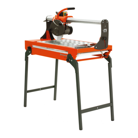
METKON chop cutting machine METACUT 302 is the ideal
abrasive cut-off machine for metallographic samples, offering
perfect solutions for efficient, versatile and high-quality
cutting.
Modern stylish outlook
Compact and powerful
Easy and quick operation
Designed for cutting large and irregular workpieces
Manually controlled cutting lever
Max. safety with electronic brake and interlocking safety
device
Stainless steel cutting bed
Suitable for both Ø300 mm and Ø250 mm cut-off wheels
High cutting capacity
METKON chop cutting machine METACUT 302 is designed for
wet cutting of large and small, regularly or irregularly shaped
workpieces of metalic, ceramic or composite materials.
METACUT 302 is a tabletop high quality cutting machine
suitable for Ø300 and Ø250 mm cut-off wheels. It has the
capacity to cut solid sections up to 115 mm in diameter.
The side access port permits the sectioning of extra-long
workpieces, as well. The machine is equipped with a
powerful motor, driving the cut-off wheel towards the
workpiece. The bottom part of the machine is a large
rubostalloy base casting. The cutting table is provided with T-
Slots increasing the versatility so that different clamping sets
can be mounted. Spacious cutting chamber and extra-
largecutting table enables easy clamping of the specimens to
be cut. The quick-clamping devices are removable to permit
the installation of conventional clamping tools to hold larger
or more intricate workpieces.
The complete system is enclosed in a protective hood with a
large shatterproof window to observe the cutting process.
The cutting chamber inside is illuminated with a powerful
LED.
New design sloping base of the cutting chamber provides
easy flowing of the cutting fluid back to the recirculating unit,
preventing the accumulation of the cooling fluid. METACUT
302 is available as both tabletop unit and optional rigid Floor
Cabinet. START, STOP, Pump and Lamp touchpad buttons are
mounted on the front panel. METACUT 302 has the highest
safety standards. The interlocking safety device does not
allow the motor to be started unless the hood is closed. The
hood cannot be opened before the motor is stopped. The
electronic brake system, which is a standard feature, brings
the cutter to a quick full stop in seconds after it has been
switched off.

6
Technical Data
Model
Order No
METACUT 302
10 05
Cutting Power, kW (S1)
3
Cutting Power, kW (S3)
4.6
Wheel Speed, RPM
2800
Operation
Manual
Wheel Diameter, (mm)
Ø300 / Ø250
Cutting Capacity, Ø (mm)
Ø115 / Ø90
Cutting Capacity, # (mm)
50 x 195 / 50 x 165
T-Slot Table Dimension, (mm)
255 x 250
T-Slot Dimension, (mm)
12
Size, WxDxH, (cm)
58 x 68 x 49
Weight, (kgs)
132
Cooling Unit, (lt)
60

7
Warranty
The METACUT 302 is guaranteed against defective material or
workmanship defects for a period of 12 months from the date
of receipt by the customer or latest 18 months after the
shipping date. The warranty is not valid if inspection shows
evidence of misuse or unauthorized repair. Warranty covers
only replacement of defective materials. If this unit need to be
returned to our factory for service, please contact your
distributor for authorization and include the following details:
Serial Number of the unit, Invoice number and date. Transport
costs belong to the customer.
NOTE
Disabling Safety switch on the METACUT 302 will void
warranty.
NOTE
Warranty does not cover the safety switch. Do not apply
excessive force to open the front door when safety switch is
locked. Otherwise, it can be broken in a short time.
Using any other brand consumables
apart from METKON brand (cut-off
wheels, cooling fluids) this warranty
will not cover:
Painting deformation and rusting on the components
Deformation and corrosion occurred on Motor, Bearings,
Clamping Devices, bearing housings, etc.
Safety Precautions
Read the below instructions carefully before use.
Place the machine on a sturdy and safe platform.
The equipment must be installed in compliance with
local safety regulations.
Only use approved METKON accessories and
consumables to achieve maximum safety and lifetime.
The equipment is not for use with saw-blade type cut off
wheels.
Follow the instructions and safety regulations when
lifting and carrying the equipment.
Be sure that the sample is securely fixed in the clamping
devices. Handle the large and sharp samples in a safe
way.
Do not put your hand in the cutting chamber during
positioning of the cutting wheel.
Do not put your hand through the opening on the side to
cut long pieces during the operation.
The equipment emits only moderate noise. However,
during the cutting process the emitted noise may be
higher. Wearing hearing protection is recommended.
Disconnect the electrical connection before servicing the
equipment.
After cutting operation, heat and sharp edges may occur.
Using protection gloves are recommended.
Do not bypass the safety switch.
Follow the periodically maintenance and keep the door
open when not working.
NOTE
METKON Instruments Inc. can make any changes
without notice on the equipment, accessories,
consumables and miscellaneous products.
Consequently; visual or written information on
the instruction manuals, technical materials, catalogues,
website, product videos and other marketing materials may
show inconsistencies and may be different from the product.

8
INSTALLATION & SET UP
Unpacking & Checking Contents of Package
Carefully remove the outer packing material and check
contents of the package. If any components are missing or
damaged, save the packing list and materials and advise your
distributor and the carrier of the discrepancy.
WARNING
METACUT 302 weights approximately 132 kg and
be sure that there are enough people (at least 4)
to lift the equipment safely for transportation. It
is recommended to wear safety shoes during transportation.
ATTENTION
METACUT 302 is bolted to a wood base for
protection during shipping. Remove the bolt
securing the unit to the wood base.
METACUT 302 is available either as bench top or with
cabinet.
METACUT 302 should be placed on a sturdy and safe
platform. Please be sure that the platform is large enough
and can stand its weight.
In order to work with equipment comfortably, it is
recommended to leave at least 1 m space from all side of
the equipment.
You can see the dimensions and weight of METACUT 302
as below:
Without Cabinet
Dimensions
W
D
H
58 cm
68 cm
49 cm
Weight
Approx. 132 kgs
With Cabinet
Dimensions
W
D
H
58 cm
68 cm
132 cm
Weight
Approx. 140 kgs
If METACUT 302 ordered without cabinet, you will need
enough space for recirculating cooling tank under the
bench.
You can see the dimensions of recirculation cooling tank
with pump as below:
Dimensions
W
D
H
55 cm
42 cm
58 cm
It is recommended to leave at least 30 cm space from all
side of the recirculating cooling tank.

9
Step by Step Unpacking
If Sent in a Carton Box (Equipment without Cabinet)
Carefully remove the outer stretch wrap, cut the strips
and remove the cover.
Place the upper box on the ground.
Open that box. Remove consumables and recirculation
coolant tank.
Open the other box. Insert the two ropes on the inner
side of the machine feet. Put a sponge material between
the ropes and machine to prevent any risk of damage.
Carefully remove the equipment from the box by using a
lifting equipment. Please consider weight of equipment
while lifting it.
Carefully remove the protective bubble wrap. Be carefull
not to damage equipment while using a knife. Remove
the protective foam on the touch screen.

10
If Sent in a Carton Box (Equipment with Cabinet)
Carefully remove the outer stretch wrap, cut the strips
and remove the cover.
Open the box and remove filling materials inside the box.
Remove the box and carefully remove the protective
bubble wrap on the equipment. Be carefull not to
damage equipment while using a knife.
Open the cabinet. Remove the consumables and
recirculation coolant tank.
Equipment is fixed on the wooden base with bolts. Lift
the equipment from the wooden base by using a lifting
equipment and then carefully remove these bolts.
Insert the lifting profiles inside the cabinet and lift the
equipment with a forklift.

11
If Sent in a Wooden Case
Carefully remove the outer stretch wrap.
Open the top cover of wooden case by removing screws.
Open the back, front and side covers in the same way
and remove filling materials inside the case.
Carefully remove the protective bubble wrap on the
equipment. Be carefull not to damage equipment while
using a knife.

12
Open the cabinet (if available). Remove the consumables
and recirculation coolant tank.
Equipment is fixed on the wooden base with bolts. Lift
the equipment from the wooden base by using a lifting
equipment and then carefully remove these bolts.
Insert the lifting profiles inside the cabinet and lift the
equipment with a forklift.
Lifting and Transportation
If equipment is sent with cabinet, follow below steps to lift
and transport:
Place the lifting profiles under the machine.
Carefully lift the equipment with a pallet jack or a forklift
by considering the weight center.
Carefully place it to the ground.
Lifting Profiles
Alternatively, you can lift the equipment from the side
with two pallet jacks or a forklift.
Use two pallet jacks to lift the equipment.
Lift from right side and left side of the equipment at the
same time.
Consider the center of gravity when lifting equipment.
Slowly lift, move and place on the ground.
Lifting from Side with Pallet Jacks
NOTE
To avoid movement of cutting motor during
transportation, the cutting shaft is fixed to the
vise assemblies or directly to the T-table with
a red stabilizer. Disassemble the stabilizer
before operating.
Stabilizer
Stabilizer

13
Installation and Set-Up
CAUTION
Follow approved procedures and take all
necessary preventive safety measures when
lifting and installing this equipment. Improper
lifting can result equipment damage.
Locate the METACUT 302 with convenient access to a 3-
phase power source. Be sure to allow a minimum space of
50 cm at the rear of the machine.
ATTENTION
The safety switch is set to the “UNLOCK”
position to lock the front door closed for
transportation. The motor does not work after
pressing the “START” button but all the display functions are
normal. Set the safety switch to the “LOCK” position to allow
the motor to run.
Electrical Installation
Before making electrical connections, check that the voltage
and frequency stated on the specification plate correspond to
the local voltage and frequency. Check that the values for
three-phase voltage, is compatible with the intended
electrical supply before installation.
Connect the mains cable of the METACUT 302 to an
appropriate electrical outlet.
Check the safety interlock switch is in the correct
position.
Open the hood, remove the bolt and flange from the hub,
disassemble the stabilizer before operating.
Close the door. Turn the instrument on from the main
switch, which is on the right hand side of the instrument.
See Cutting Operation section for operation.
Press “START” and “STOP” buttons and observe from the
window that the cutting wheel shaft rotates clockwise
when looked at from the left.
If the shaft rotation is incorrect, then see Cut-Off Wheel
Rotation Direction section.
ATTENTION
Connect the unit to the grounded mains
voltage. The METACUT 302 requires a 3-phase
electrical supply and Earth/Ground. A neutral
(N) conductor is not required.
WARNING
Electrical Shock Hazard. A qualified electrical
technician should perform all hard wiring and
electrical maintenance.
Disconnect the power supply before making any
electrical adjustments.
Make sure that the supply voltage and frequency is
correct. Check the values from the machine identification
plate located at the rear of the machine
Voltage / Frequency
Operational
Power Range
Fuse Rating
230 V, 50/60 Hz. 3 ph.
200 - 250 V
20 A (C Type)
400 V, 50/60 Hz. 3 ph.
360 - 440 V
10 A (C Type)
Identification Plate
Connect the equipment to the grounded mains voltage.
Please supply suitable 3-phase power plug according to
power socket.
Power Cable
You can see an example of connection method using an
electric terminal.
Power Connection

14
Cooling Unit
Recirculating cooling tank is an optional accessory of
METACUT 302. So, it is not required to connect the
METACUT 302 to the city water and drain.
Recirculating cooling tank should be placed under the
bench level.
All connection hoses for recirculating cooling tank will be
supplied with the equipment.
Recirculation Cooling Tank
If you ordered METACUT 302 as benchtop, in this case
you may need to open a hole on the bench for water
hoses or leave enough space at the backside of the
bench. Please be sure that the hole or space is large
enough for water hoses.
Outer diameters of water inlet and drain hose of
recirculating cooling tank are as below:
One x Water inlet hose (Black): Ø 23 mm
One x Drain hose (White): Ø 58 mm
The cutting surface is cooled by four spray nozzles whose
water jets hit both the cutting wheel and the specimen. This
provides an efficient cooling of the sample and prevents the
overheating of the surface structure.
Coolant is lost during the cutting process because of
evaporation or left in the cutting chamber or components. For
the best cutting performance and corrosion protection,
replace the coolant regularly (max. 3 months)
Follow below steps to make recirculating cooling tank ready
to use:
Put the pump inside the cooling tank and fix it using four
screws.
Fix the small hose to the pump outlet by using hose clips.
Connect the power cable to of the METACUT 302 to the
electric socket of the pump.
Put the magnetic collector rod (optional) inside the
cooling tanks.
Put a filter paper inside the filtration section.
Connection and Components of Recirculation Cooling Tank
Move the cooling tank inside the cabinet.
Put the large drain hoses inside filtration section.
Fill the tank with a mixture at a ratio of 95% clean water
+ 5% METCOOL cutting fluid until the mixture level
comes to 2-3 cm below the top. Water hardness should
be 5-20 °dH in German Hardness and should not contain
bacteria and chemical salts. METCOOL ratio should not
less than 3% and should not more than 6%. If
concentration is below 3%, corrosion may occur inside
the cutting chamber. If concentration is more than 6%,
foaming effect may occur.
Inside the Cabinet of METACUT 302
Pump electric
socket
Pump
Outlet
Filtering
Section
Holes for Magnetic
Collector rods
(Optional)

15
Leveling the position of the equipment
You should adjust the level of the machine before use.
Otherwise, there may be vibration during cutting operation
and problem on the water drainage. Follow below instruction
to level the machine.
Put a levelling tool on the T-slotted table in both X-axis
and Y-axis direction. It is best to use two levelling tool at
the same time, one of them is put in X-axis and the other
one is put in Y-axis direction.
Check if the bulb is between the lines. If the bulb is not
between the lines, adjust the height of the foot by turning
the nuts with a wrench tool.
Levelling Tool Foot
Mounting Clamping Devices
When assembling the rear jaw of a clamping device, make
sure it is positioned perpendicular to the cutting wheel. You
can check it with a set square. Otherwise, the cut side of the
specimen will not be square to the sample axis.
If you are using two clamping devices, the jaws at the both
sides will need to be set to the same alignment.
Perpendicularity
Safety
THE METACUT 302 machines conform to the highest
standards of safety regulations. The cutting motor cannot be
started unless the front door are closed. Opening the front
door during cutting operation is not possible. The front door
can be opened by the operator only after the cutting motor
had stopped. The electronic brake system brings the cutting
motor to a standstill in a few seconds.
The safety switch is delivered on UNLOCK
position for safety transportation. If you
START the equipment in this situation all
the functions (light, table movement, and
pump) will work except cutting motor. SET
THE SAFETY SWITCH TO “LOCK” POSITION TO ALLOW
MACHINE OPERATION.
Safety Switch (Located on the right side of equipment)
Cut-Off Wheel Rotation Direction
The cutting wheel shaft has to rotate clockwise when looked
at from left of the equipment. Do not operate the equipment
if the cut-off wheel is rotating in the wrong direction.
If the cut-off wheel rotates in the wrong direction, follow the
steps below.
Disconnect all electrical power
Interchange two of the phase supply leads in the plug.
Reconnect the electrical power and recheck.
Noise Level
Approximately 65 dB is measured at idle running at a distance
of 1 meter from the machine.

16
CONTROL PANEL
METACUT 302 has simple and easy to use operator panel with
buttons. Cooling pump, LED illumination and cutting motor
can be controlled easily.
METACUT 302 Control Panel
Control Button Functions
Light
Pump
Start
Stop
Loading & Unloading of Specimen
In order to load the specimen into the cutting chamber, the lid
must be raised first. Be sure that the hood is completely
opened. After the specimen is loaded and clamped, lower the
lid carefully.
Be sure that the upper part of the Safety Switch on the lid has
interlocked to the bottom part. After that, you can start the
cutting operation.
Loading and Clamping Specimen
OPERATION
Mounting of Abrasive Wheel
Insert the arbor pin in the hole of the hub and loosen the bolt
with a wrench by turning it clockwise. Take the arbor pin out.
Remove the bolt and the flange. Remove the abrasive wheel
carefully.
Spindle Locking and Mounting of Abrasive Wheel
Mount the new wheel onto the arbor by placing cardboard
disc on either side of the wheel to prevent damage. Then refit
flange and bolt, tightening the bolt slightly with the wrench.
Remove the arbor pin.
For a final check, spin the wheel by hand to see if it has been
installed correctly and confirm that the wheel remains in a
vertical alignment as it rotates.
IMPORTANT
Do not leave the arbor pin inserted in the hub.
Injury or damage may happen if motor is
started accidentally.
ATTENTION
Be sure that the cut-off wheel is suitable with
your specimen. Choose an appropriate cut-off
wheel according to your specimen material.
Inappropriate cut-off wheels may cause
serious damages on the mechanical parts on the machine,
due to high vibration, heat generation and strain. The
damages due to wrong cut-off wheel usage or non-METKON
brand wheels are out of warranty!

17
Sample Clamping and Positioning
It is very important to ensure that the sample is fixed firmly in
the clamping device. The METACUT 302 can be equipped
with a left –hand cam activated quick acting clamping device
and a right –handspring type clamping vise (or other optional
vises) mounted on the T-slotted table capable of handling any
kind of samples to be cut.
It is possible to detach the complete device so that very large
parts can be clamped directly on the T-table. It is also
possible to replace the vices on the T-table, if required. The
standard clamping devices of METACUT 302 can fix most of
the sample shape and size.
Vise Assembly
Be sure that the clamping device is fixed properly on the
T-table.
Be sure that the specimen is clamped properly. Check the
specimen with your hand after clamping.
Follow below directions to clamp specimen on the cam
activated quick clamping device:
1. Release the clamping lever and open the vices
completely.
2. Place the sample and push clamping jaws against
the sample rigidly.
3. Push clamping lever so that the sample is held
firmly.
When clamping the object to be cut, it should be
positioned to obtain equal support on both sides of the
cut.
DO NOT apply excessive force when pushing the
clamping levers as this can damage the cams. Use
moderate hand pressure.
Fix long and big specimens from two side at least.
Cutting Operation
Turn on the equipment from the main power switch to
the right side of the machine.
Main Power Switch
Turn on the light from the control panel.
Clamp your specimen on the table correctly.
Adjust water nozzles according to specimen. Turn on the
pump from the control panel. Be sure that water flow is
good.
Close the hood and run the cutting motor by pressing
“START” button from the control panel.
Slowly feed the cutting wheel to the sample by cutting
arm at the right side of the equipment.
Do not apply excessive during cutting. If you feel
vibration, strain and see a lot of spark, reduce the force.
Otherwise, there may be burns on the sample surface,
cut-off wheel can be broken and machine can be
overloaded.
At the end of the cutting process, return the lever to its
starting position and turn off the machine by pressing
“STOP” button from the control panel.
Turn off the pump from the control panel.
Open the hood and take your sample.

18
SERVICE AND MAINTENANCE
Maintenance
METACUT 302 may be exposed to harsh conditions especially
when cutting large parts. Therefore, it is very important to
carry out all maintenance steps on time to use machine
without problem for a long time.
Strictly follow daily, weekly and monthly maintenance
recommendations.
Use only “METCOOL” cutting fluids to obtain maximum
corrosion protection and cooling properties.
Use only “METCOOL-NF” cutting fluid if you continuously cut
reactive metals like copper, brass, cobalt, aluminum, tungsten
carbide, etc… METCOOL-NF has perfect corrosion protection
for the machine when cutting these parts.
Daily Maintenance
CLEAN THE CUTTING CHAMBER
At the end of working day, clean all area of the cutting
chamber with washing gun inside the cutting chamber.
Washing Gun
If you do not clean the cutting chamber, the small metallic
particles will cause corrosion in any parts inside the cutting
chamber (T-table, clamping devices, shafts, paintings etc…).
KEEP DRY THE CUTTING CHAMBER
After cleaning, dry the cutting chamber and clamping devices
with an air gun. If you leave the cutting chamber wet, this
may cause corrosion in any parts inside the cutting chamber
(T-table, clamping devices, shafts, paintings etc…).
KEEP HOOD OPEN
If you do not use the equipment for a long time, keep the
hood open to avoid humidity inside the cutting chamber. The
humidity may cause corrosion in any parts inside the cutting
chamber (T-table, clamping devices, shafts, paintings etc…).
CHECK THE FILTERATION SECTION OF THE
RECIRCULATION COOLING TANK
At the end of working day, check the filtration section.
Depending on the intensity of use, it can be filled quickly with
the swarfs.
Filtration Section
If the filtration section is filled with swarfs, empty the swarfs
inside the filtration section and clean or replace the paper
filter.
Filter
If recirculating cooling tank is equipped with optional
magnetic collector rod, check them if they filled with
magnetic particles. If they full, empty them by pulling the
center rod.
Removing the Magnetic Collector Rod
Cleaning the Magnetic Collector
Magnetic
Collector Rod
Filtration
Section
Pull from these
handles when
you picking the
rod from the
cooling tank.
Pull the center rod
to let metallic
particles drop.
Washing
Gun

19
Weekly Maintenance
CHECK THE CUTTING FLUID
Open the lid of the cooling water tank. Check the pH value of
the cooling fluid. If the pH value is below the 8.5, change the
cooling fluid with the new mixture at a ratio of 95% clean
water + 5% METCOOL.
If pH value is not below 8.5, only check whether the water
level is low. If water level is low, add 95% clean water + 5%
METCOOL cutting fluid mixture until the water level comes to
2-3 cm below the top.
Monthly Maintenance
CHANGE THE CUTTING FLUID
The cutting fluid should be changed periodically. Because, it
may lose its cooling, anti-corrosion and anti-bacterial
properties as you use it.
Follow below steps to change the cutting fluid:
Move out the cooling thank from the cabinet.
Remove the hoses and the cable connection of the
pump.
Remove filter basket and magnetic collector rod
(optional).
Open the lid of the tank and drain all the cutting fluid.
Clean inside the tank, lid, pump, filter basket and
magnetic collector rod properly.
Fill the tank with a mixture at a ratio of 95% clean water
+ 5% METCOOL cutting fluid until the mixture level
comes to 2-3 cm below the top. Water hardness should
be 5-20 °dH in German Hardness and should not contain
bacteria and chemical salts. METCOOL ratio should not
less than 3% and should not more than 6%. If
concentration is below 3%, corrosion may occur inside
the cutting chamber. If concentration is more than 6%,
foaming effect may occur.
Close the lid, put the filter basket and magnetic collector
rods, connect to hoses, the pump and cable connection.
Place the cooling tank inside the cabinet.
Recirculation Cooling Tank
LUBRICATE THE CLAMPING DEVICES
Lubricate the all-moving parts of the clamping devices with a
slideway oil or thin grease. (Never use grease containing
Molybdenum Disulphide or graphite, which can impair the
clamping ability of the Vise.)
Lubricating the Clamping Devices
Check the clamping force of the cam activated quick clamping
devices. When insufficient, readjust the clamping force, by
using the setscrew as shown in below:
Adjusting Clamping Force

20
Troubleshooting
ERROR
DESCRIPTION
ACTION
The cut-off wheel is not rotating
The Safety Switch may be in UNLOCK
position
Turn the safety switch to LOCK
position.
The hood may not closed properly
Close the hood properly.
Burning remarks on the cutting surface
The cut-off wheel is not compatible
with the cut piece
Use proper cut-off wheel.
See consumables section for the
correct cut-off wheel selection.
High cutting force
Reduce the force
Insufficient cooling
*Check that there is enough cooling
fluid in the tank.
*Be sure that the cooling nozzles are
correctly positioned on the specimen
surface and the cut-off wheel.
Unwanted burrs on the sample
The cut-off wheel is not compatible
with the cut piece
Use proper cut-off wheel.
See consumables section for the
correct cut-off wheel selection.
High cutting force at the end of cycle
Reduce the force before the end of
the operation.
Improper clamping of the sample
Support the sample from both sides.
Cut-off wheel breaks
Incorrect mounting of the cut-off wheel
Check the mounting of the cut-off
wheel and be sure that the nut and
the flange is set properly
The cut-off wheel is not compatible
with the cut piece
Use proper cut-off wheel.
See consumables section for the
correct cut-off wheel selection.
High cutting force
Reduce the force
Improper clamping of the sample
Support the sample from both sides.
The Lexan window is blurred
Insufficient cleaning
Clean the Lexan window with a mild
soapy water (Do not use the cooling
fluid with cleaning hose)
Table of contents
Other Metkon Cutter manuals
