Metkon MICRACUT 152 Administrator Guide

1
metkon.com
OPERATION & INSTRUCTION MANUAL
PRECISION CUTTER

2
EC Declaration of Conformity
Manufacturer : Metkon Instruments Inc.
Address : Demirtas Dumlupinar Organize Sanayi Bolgesi
Ali Osman Sonmez Cd. No: 14 Bursa / TURKEY
Model No : MICRACUT 152
Herewith declares that;
Precision Cutter
is in conformity with the provisions of the Machinery Directive (directive 2006/42/EEC), as amended, and with national
implementing legislation;
is in conformity with the provisions of the Low Voltage Directive (directive 2014/35/EU), as amended, and with national
implementing legislation;
is in conformity with the provisions of the EMC Directive (directive 2014/30/EU), as amended, and with national
implementing legislation;
And furthermore declares that
the following (parts/clauses of) standards have been applied
EN ISO 12100:2010, TS EN 60204-1, TS EN IEC 61000-6-2, TS EN 61000-6-4
Authorized Person: ERCIN SENAY
Position: Manager of Research and Development Department
Year: 2019
Bursa / Turkey

3
Index
DESCRIPTION ............................................................................................................................ 4
Design .....................................................................................................................................................................................4
Technical Data ........................................................................................................................................................................5
Warranty .................................................................................................................................................................................6
Safety Precautions ..................................................................................................................................................................6
INSTALLATION & SET UP........................................................................................................... 7
Unpacking & Checking Contents of Package ...........................................................................................................................7
Step by Step Unpacking...........................................................................................................................................................7
Installation and Set-Up ...........................................................................................................................................................9
CONTROL PANEL......................................................................................................................14
Control Button Functions ...................................................................................................................................................... 14
Operation Parameter Ranges ................................................................................................................................................ 14
OPERATION ..............................................................................................................................14
Mounting of Cutting Wheel ................................................................................................................................................... 14
Blade Dressing ...................................................................................................................................................................... 15
Cutting Operation.................................................................................................................................................................. 15
SERVICE AND MAINTENANCE ..................................................................................................16
Maintenance ......................................................................................................................................................................... 16
Troubleshooting.................................................................................................................................................................... 17
ACCESSORIES AND CONSUMABLES.........................................................................................18
Clamping Devices and Accessories ....................................................................................................................................... 18
Consumables......................................................................................................................................................................... 19
TECHNICAL DOCUMENTATION ................................................................................................21
Customer Service .................................................................................................................................................................. 21
4
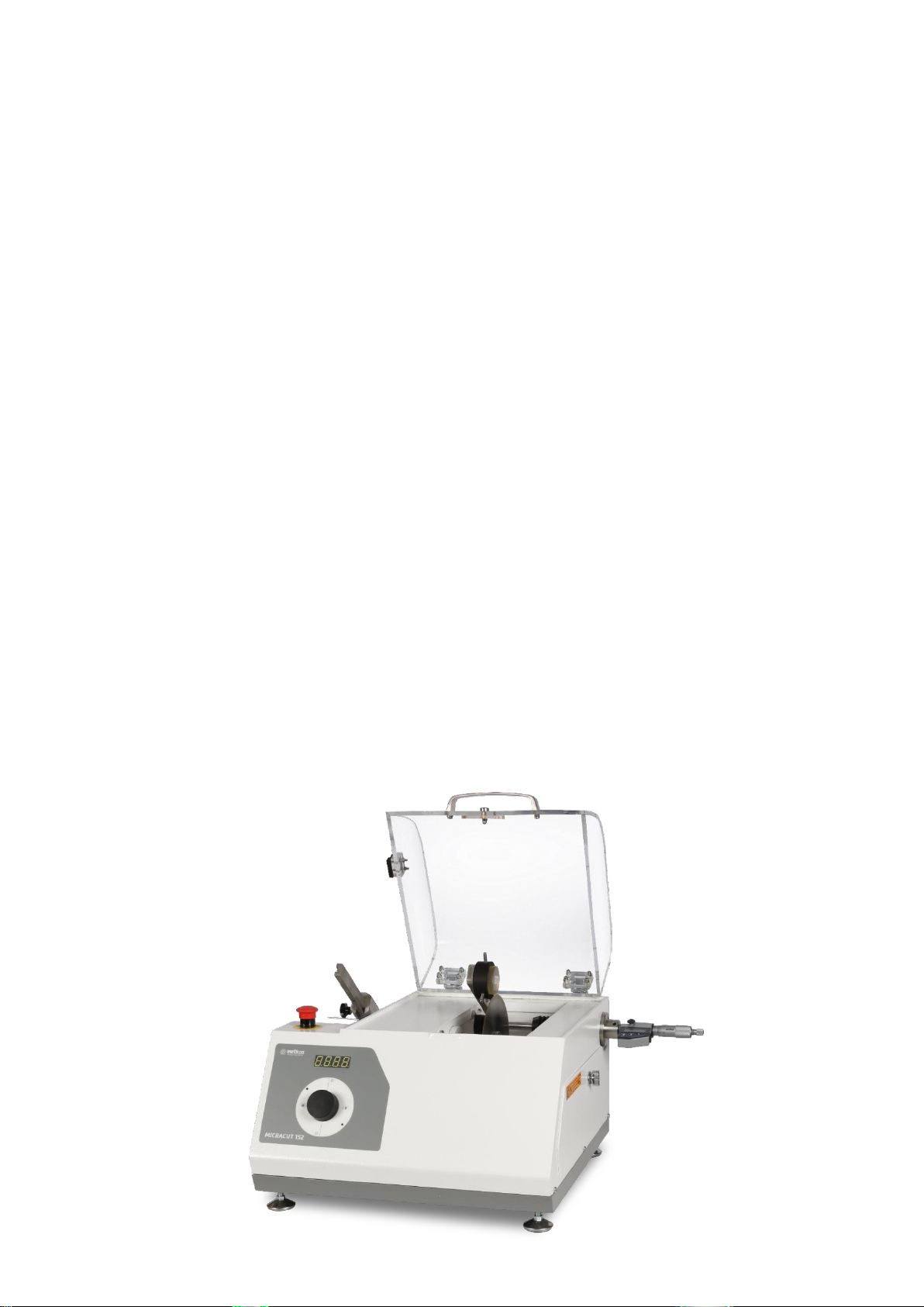
DESCRIPTION
Design
MICRACUT 152 precision cutters are used for precise and
deformation-free cutting of “Metals, Ceramics, Electronic
Components, Crystals, Composites, Biomaterials, Sintered
Carbides, Minerals, etc.” MICRACUT 152 has its place in
virtually any metallurgical, geological, electronics, research,
biomedical or industrial laboratory. The applications are
endless.
•Modern and sturdy design
•Easy to use control panel with ergonomic turn-knob
•Precise micrometer with digital readout
•Gravity feed system
•Automatic stop at the end of cut
•Transparent protection hood with magnetic safety
switch
•Inbuilt recirculation coolant tank
MICRACUT 152 accommodates diamond and abrasive wheels
up to 175 mm (7”) diameter and the speed range is between
50 and 1500 rpm. Modern-looking touch pad controls with
ergonomic turn knob allows fast and easy setting of wheel
speed and increases productivity. The gravity feed loading
design minimizes sample deformation. The sliding weight arm
with counterweight allows precise force application. The
digital micrometer enables the operator to set the cutting
width with a resolution of 1 micron. The digital micrometer is
interchangeable and the customer can mount other types of
micrometers if and whenever required. The coolant tray is
removable from the instrument for easy cleaning. MICRACUT
152’ s cutting chamber is fully enclosed by a transparent
hood. Blade dresser is optionally available. At the end of the
cut, the motor automatically stops and an audible signal
notifies the operator.
Optional Cutting Table Attachment is available for manual
cutting of extra flat large specimens and PCB’s.
MICRACUT 152 precision cutters are capable of cutting most
materials such as, brittle or ductile metals, hard or soft
metals, composites, ceramics, rocks, biomaterials, laminates,
etc. They are designed for cutting all types of materials with
minimal structural deformation.
The structural integrity of the sample is maintained through
MICRACUT 152's design and operation. Additionally, low kerf-
loss and sample holding versatility makes the MICRACUT 152
an essential part of the modern day laboratory. The cut
surface is ready for microscopic examination with minimal
polishing.
Safety
MICRACUT 152 precision cutters has the highest safety
standards. The magnetic safety switch does not allow the
motor to be started unless transparent hood is closed. If
transparent hood is opened during cutting, the motor
immediately stops automatically. Easily accessed and
operated emergency stop button ensures immediate shut
down. Soft closing feature of transparent hood protects
fingers from risk of injury.

5
Technical Data
Model
Order No
MICRACUT 152
16 05
Disc Diameter, mm
Ø175 mm
Cutting Capacity, mm
Ø50 mm
Cutting Motor Power, W
100 W
Disc Speed, RPM
50 RPM - 1500 RPM
Cutting Method
Chop
Parallel Cutting in X-Axis
Yes
X-Axis Positioning, mm
25 mm
Cooling Unit, lt
850 ml (integrated)
Dimensions, WxDxH, mm
510 x 430 x 340h mm
Weight, kgs
28 kgs

6
Warranty
The MICRACUT 152 is guaranteed against defective material or
workmanship for a period of 12 months from the date of receipt
by the customer or latest 18 months after the shipping date.
THE WARRANTY IS NOT VALID IF INSPECTION SHOWS
EVIDENCE OF MISUSE OR UNAUTHORIZED REPAIR. Warranty
covers only replacement of defective materials. Should this unit
need to be returned to our factory for service contact your
distributor for authorization and include the following details:
Serial Number of the unit, Invoice number and date. Transport
costs belong to the customer.
NOTE
Disabling Magnetic Safety switch on the MICRACUT 152 will
void warranty.
Using any other brand consumables
apart from METKON brand (cut-off
wheels, cooling fluids) this warranty
will not cover:
Painting deformation and rusting on the components
Deformation and corrosion occurred on Motor, Bearings,
Clamping Devices, bearing housings, etc.
Safety Precautions
Read the below instructions carefully before use.
Place the machine on a sturdy and safe table.
The equipment must be installed in compliance with
local safety regulations.
Only use approved METKON accessories and
consumables to achieve max. safety and lifetime.
The equipment is not for use with saw-blade type cut
off wheels.
Follow the instructions and safety regulations when
lifting and carrying the equipment.
Be sure that the sample is securely fixed in the
clamping devices. Handle the large and sharp
samples in a safe way.
The equipment emits only moderate noise. But
during the cutting process the emitted noise may be
higher. Wearing hearing protection is recommended.
Disconnect the electrical connection before servicing
the equipment.
After cutting operation heat and sharp edges may
occur. Using protection gloves are recommended.
Do not bypass the safety switch.
Follow the periodically maintenance and keep the
hood open when not working.
NOTE
METKON Instruments Inc. can make any changes
without notice on the equipment, accessories,
consumables and miscellaneous products.
Consequently; visual or written information on
the instruction manuals, technical materials, catalogues,
website, product videos and other marketing materials may
show inconsistencies and may be different from the product.
7
INSTALLATION & SET UP
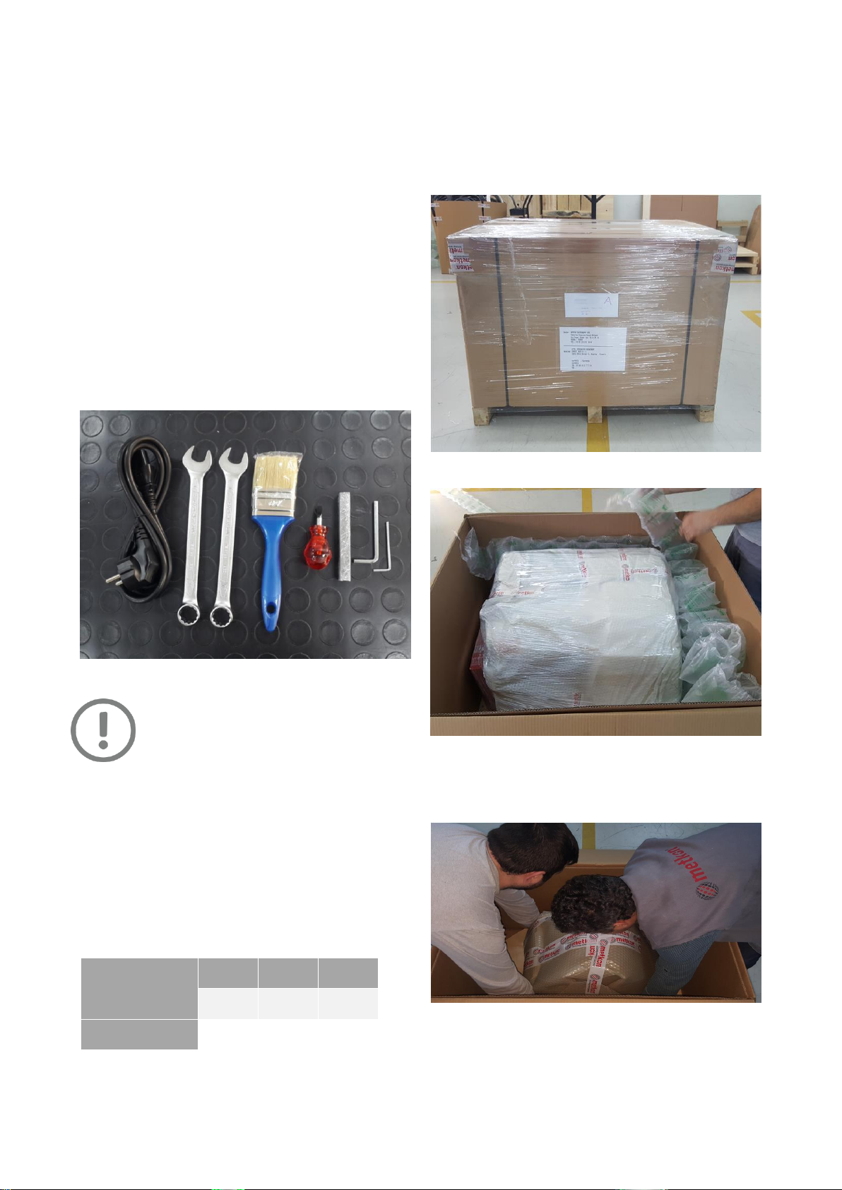
Unpacking & Checking Contents of Package
Carefully unpack and check contents of the package. If any
components are missing or damaged, save the packing list
and materials and advise your distributor and the carrier of
the discrepancy.
Power Cable, 1.8 mt, 1 piece
Combination Wrench, 17mm, 2 pieces
Brush, 1 piece
Screwdriver, 6.5 x 25, 1 piece
Dressing Stone, 10 x 10 x 100 mm, 1 piece
Hex Key, 4 mm, 1 piece
Hex Key, 2.5 mm, 1 piece
WARNING
The MICRACUT 152 weighs 28 kgs and be sure
that there are enough people to safely lift the
unit from the shipping carton. It is
recommended to wear safety shoes during
transportation
The MICRACUT 152 is shipped completely assembled except
its digital micrometer for safely shipment.
MICRACUT 152 is only available as bench top.
MICRACUT 152 should be placed on a sturdy and safe
platform. Please be sure that the platform is large enough
and can stand it’s weight.
You can see the dimensions and weight of MICRACUT 152
as below:
Dimensions
W
D
H
510 mm
430 mm
340 mm
Weight
Approx. 28 kgs
Step by Step Unpacking
If Sent in a Carton Box
Carefully remove the outer stretch wrap, cut the strips
and remove the cover.
Open the box and remove filling materials inside the box.
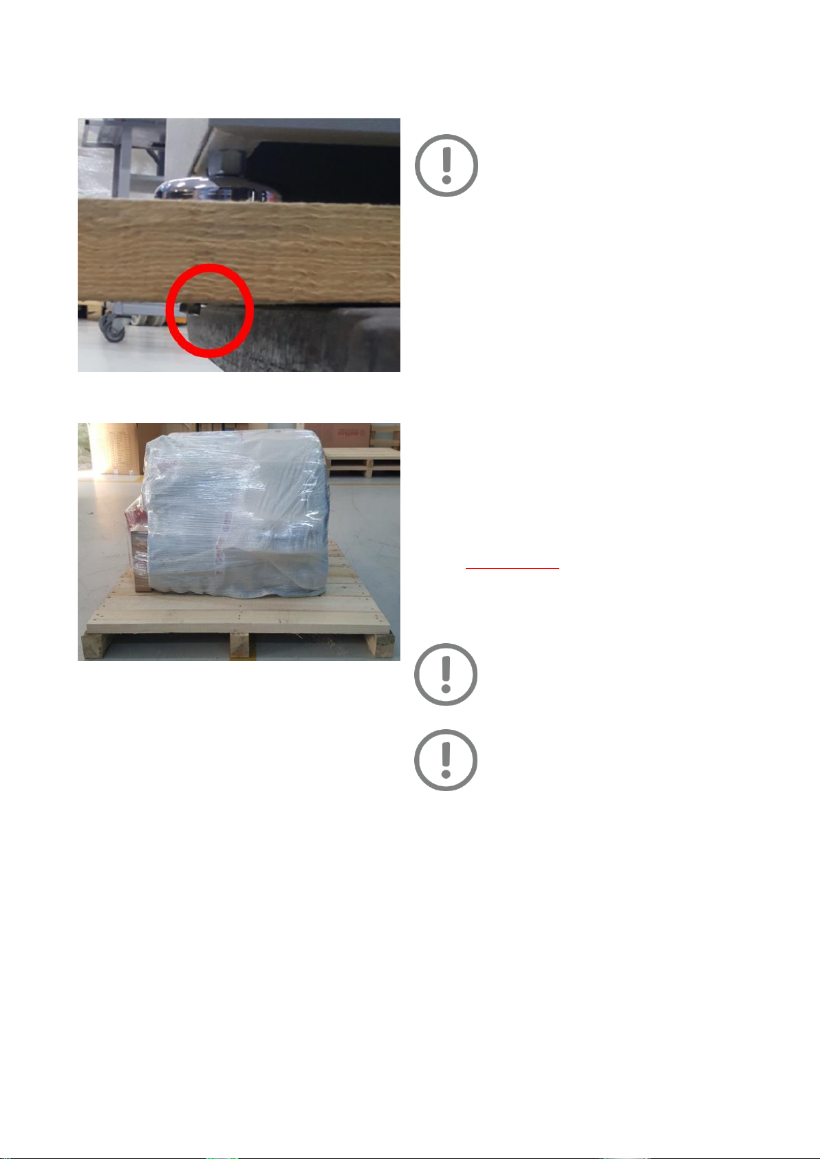
Remove the equipment from the box by holding wooden
base at the bottom. Please consider weight of equipment
when lifting it. Lift the equipment by considering the
center of gravity.
8
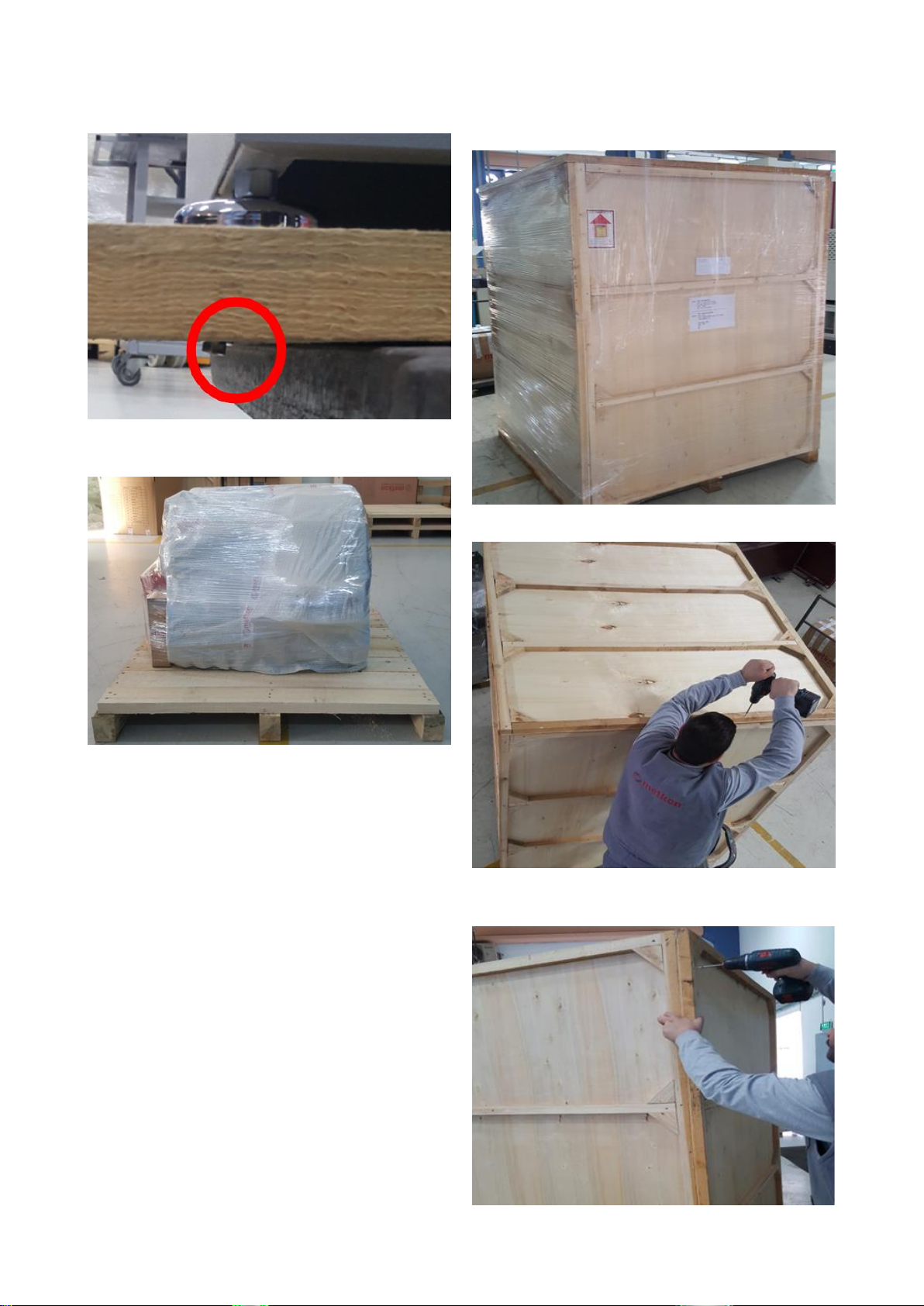
Equipment is fixed on the wooden base with bolts.
Carefully remove these bolts.
Carefully remove the protective bubble wrap. Be carefull
not to damage equipment while using a knife.
If Sent in a Wooden Case
Carefully remove the outer stretch wrap.
Open the top cover of wooden case by removing screws.
Open the back, front and side covers in the same way
and remove filling materials inside the case.
9
Equipment is fixed on the wooden base with bolts.
Carefully remove these bolts.
Carefully remove the protective bubble wrap. Be carefull
not to damage equipment while using a knife.
Installation and Set-Up
CAUTION
Follow approved procedures and take all
necessary preventive safety measures when
lifting and installing this equipment. Improper
lifting can result equipment damage.
The MICRACUT 152 is shipped completely assembled except
its digital micrometer for safely shipment. It is designed for
table-top placement. After unpacking select a smooth
location to place the MICRACUT 152. Then, adjust the leveling
feet to make the equipment parallel (set-square). Locate the
MICRACUT 152 with convenient access to a grounded type
electrical receptacle.
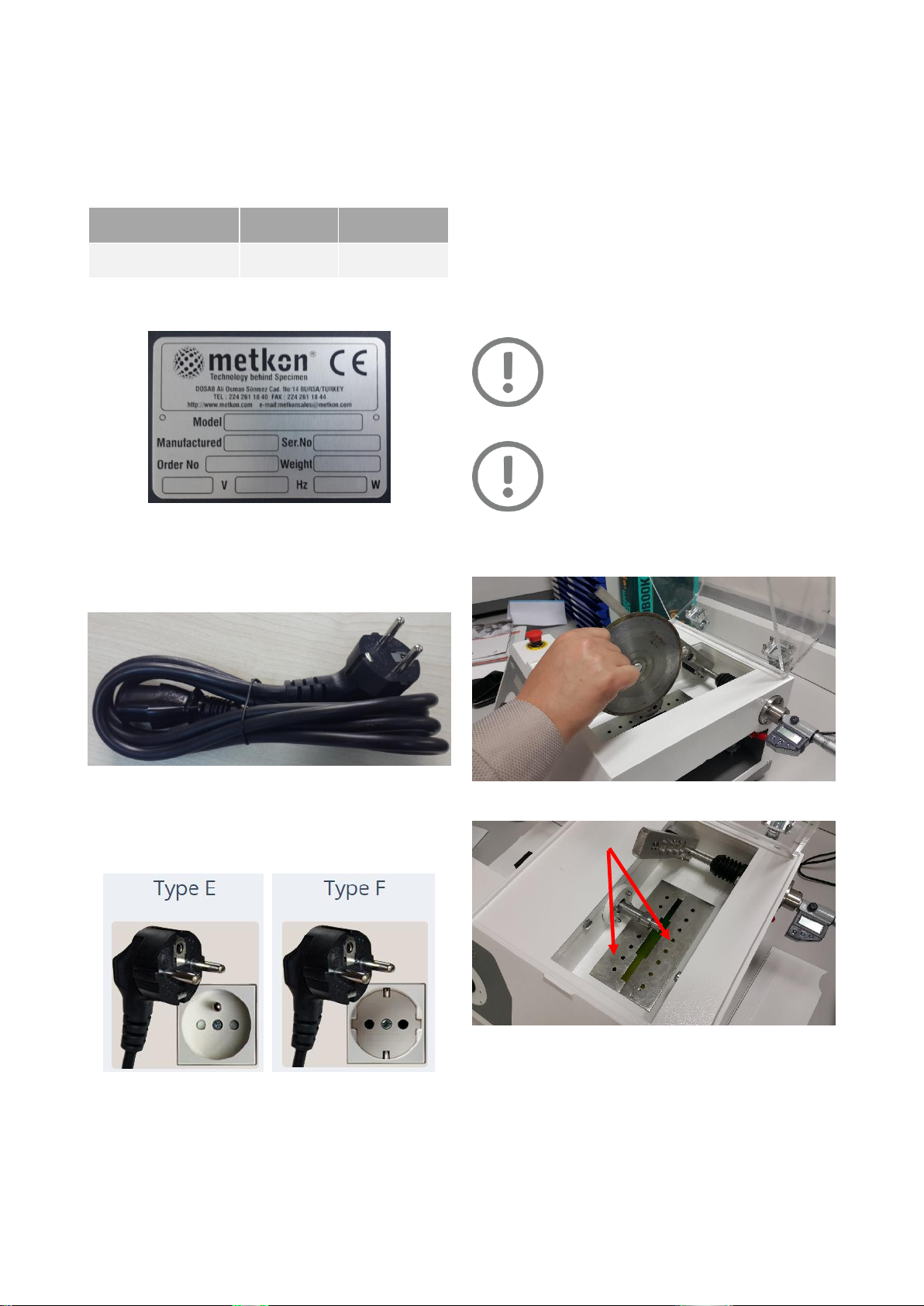
Electrical Installation
Before making electrical connections, check that the voltage
and frequency stated on the specification plate correspond to
the local voltage and frequency. Check that the values for
one-phase grounded voltage, is compatible with the intended
electrical supply before installation.
Connect the mains cable of the MICRACUT 152 to an
appropriate electrical outlet.
Close the door. Turn the instrument on from the main
switch, which is on the backside of the instrument.
See Cutting Operation section for operation.
Press “START” and “STOP” buttons and observe from the
window that the cutting wheel shaft rotates clockwise
when looked at from the left.
ATTENTION
Connect the unit to the grounded mains
voltage. The MICRACUT 152 requires a 1-phase
electrical supply.
WARNING
Electrical Shock Hazard. A qualified electrical
technician should perform all hard wiring and
electrical maintenance
10
Disconnect the power supply before making any
electrical adjustments.
Make sure that the supply voltage and frequency is
correct. Check the values from the machine identification
plate located at the rear of the machine
Voltage / Frequency
Operational
Power Range
Fuse Rating
115 V, 50/60 Hz. 1 ph.
100 - 125 V
6 A (C Type)
230 V, 50/60 Hz. 1 ph.
200 - 250 V
6 A (C Type)
Identification Plate
Connect the equipment to the grounded mains voltage.
Power cord will be supplied with the equipment.
Length of the power cable is 1.8 meters
Power Cable
You can see suitable power sockets as below. If you have
not suitable power socket, in this case you should supply
a suitable power cord.
Cooling Unit
The MICRACUT 152 uses the “drag” principle of lubrication
with the lubricant carried to the sample on the periphery of
the wheel. METCOOL Cutting Fluid reduces cutting time and
produces superior quality cuts. Its use promotes effective
lubrication which allows the diamond particles to cut cleanly.
Coolant is lost during the cutting process because of
evaporation or left in the cutting chamber or components. For
the best cutting performance and corrosion protection,
replace the coolant regularly (max. 1 month)
IMPORTANT
ONLY water-based cooling fluids has to be
used. Use of alcohol or oil based flammable
cooling fluids are strictly FORBIDDEN because;
the vapor is potentially EXPLOSIVE when
ignited.
CAUTION
Do not run the pump dry for more than 30
seconds.
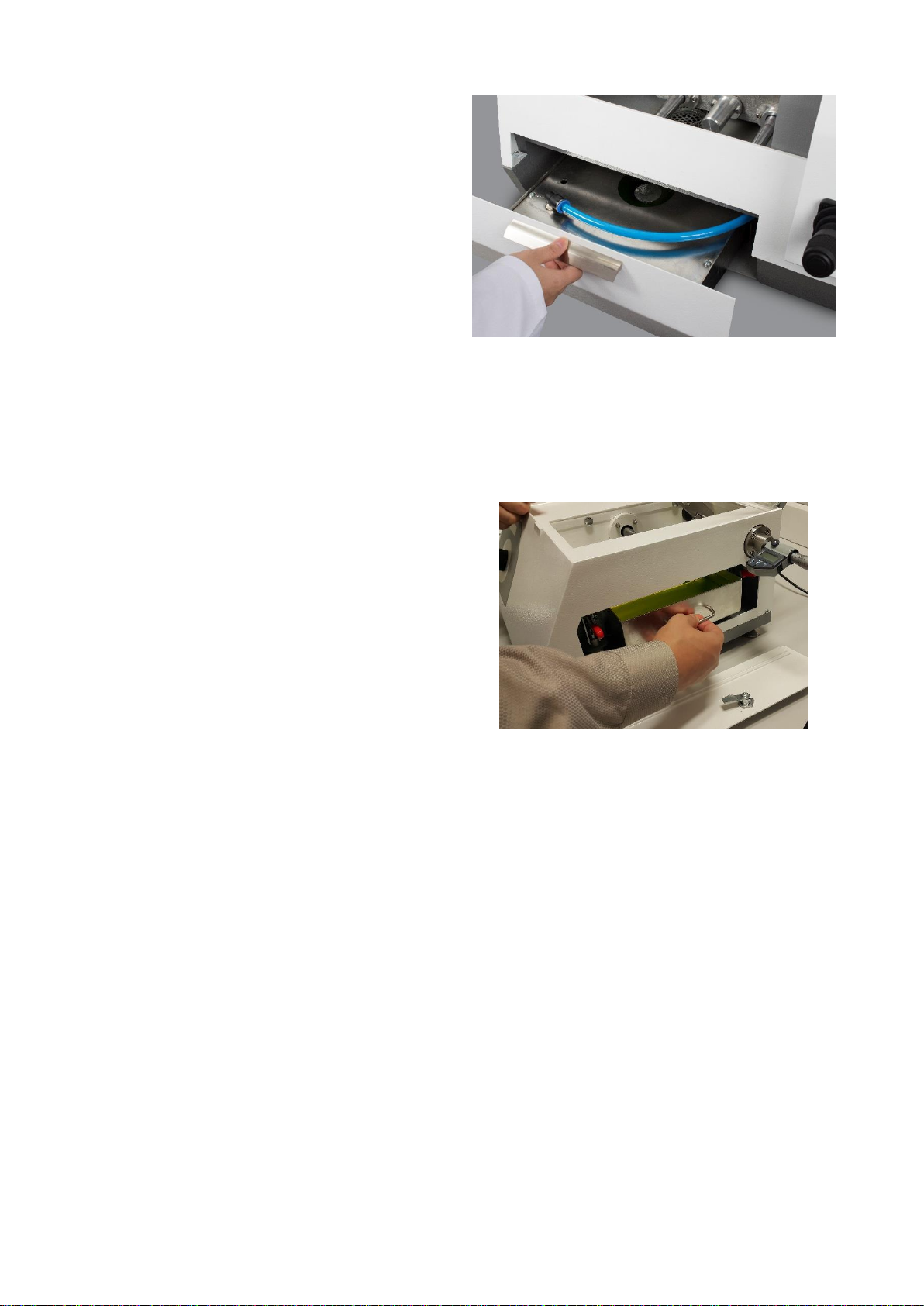
For removing the water tank, please follow the below steps:
Remove the cutting-wheel.
Open the covers which are under the wheel

11
Open the side cover.
Open the RED fixers of the coolant tank to release the
tank.
Pull out the coolant tank for re-filling the cutting fluid.
Fill the Lubricant Pan with Fluid to a level that will
immerse wheel approximately 6-7 mm.
Fill the tank with a mixture at a ratio of 95% clean water
+ 5% METCOOL cutting fluid until the mixture level
comes to 5 mm below the top. Water hardness should be
5-20 °dH in German Hardness and should not contain
bacteria and chemical salts. METCOOL ratio should not
less than 3% and should not more than 6%. If
concentration is below 3%, corrosion may occur inside
the cutting chamber. If concentration is more than 6%,
foaming effect may occur.
Push the recirculation tank into place again and follow
the steps backwards.
The recirculation unit should be checked for cooling
water every day.
Mounting of Micrometer
MICRACUT 152 is shipped completely assembled except its
digital micrometer for shipment safety. Please follow the
following steps to install the digital micrometer:
Insert the battery to the micrometer.
Micrometer
Insert the micrometer to its flange on the equipment and
push towards to the body of the equipment.
When you completely push the micrometer tighten the
screw for completing the installation. Do not tighten too
much as the micrometer will not be able to push the
cutting arm.
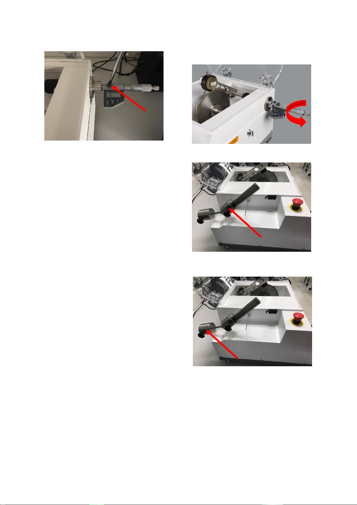
12
To arrange the sensitivity of the micrometer, tighten or
loosen the screw indicated on the below photo.
Mounting Clamping Devices
Metkon offers a wide range of specimen holders for the
MICRACUT 152.
Loosen the Set screw and slip the Counter Balance Weight
to the rear of the Shaft to hold the Support arm in an
upright position.
Select the proper Chuck for the particular application and
clamp the Specimen in place.
Attach the loaded Chuck to the Support arm with the
Chuck Mounting Thumb Screw.
After the Chuck is secured, move the holding arm to the
far left by adjusting the Micrometer Head.
Slide the Counter-Balance Weight toward the front of the
unit until balance is achieved and tighten the Set Screw.
Fasten the Sample properly: the samples must never
move around in the specimen holder during cutting.
Movements may lead to damage of the cut-off wheel and
sample will invariably cause a bad cutting quality.
Cut-Off Switch Mechanism
When the specimen is cut completely, the support arm drops
to the lowest position due to the effect of gravity. The support
arm falls on the wire switch, allowing the motor to stop
automatically.
Micrometer Adjustment and Weight Selection
Adjust the Micrometer to position the specimen for
cutting.
Weight can be applied to the work in increments of 100
grams by movement of sliding weight.
Intermediate Weights can be applied through careful
adjustment of the Counter-Balance Weight at the rear of
the Support Arm.
Counter-Balance Weight
Heavy Loads cause surface damage to the Specimen,
therefore light weights are recommended.

13
Mounting PCB Cutting Table
Disassemble the screws of the cover and remove the
cover of the MICRACUT 152. If your sample has small size,
you do not have to remove the cover.
Place the table on the equipment. Be sure that the
magnetic switch is securely closed.
You can easily and safely cut flat specimens with this
table.
Safety
The MICRACUT 152 machines conform to the highest
standards of safety regulations. The cutting motor cannot be
started unless the hood is closed. In case of opening the hood
during cutting operation, the cutting motor immediately stops.
Safety Switch
Noise Level
Approximately 62 dBa is measured at idle running at a
distance of 1 meter from the machine.
14
CONTROL PANEL
MICRACUT 152 has a modern looking and easy to use operator
panel with buttons and knob. It has specially designed to
increase operator comfort and maximize productivity.
MICRACUT 152 Control Panel
Control Button Functions
Start
Stop
Operation Parameter Ranges
Cutting Wheel Speed (RPM) : 50 –1500 RPM
OPERATION
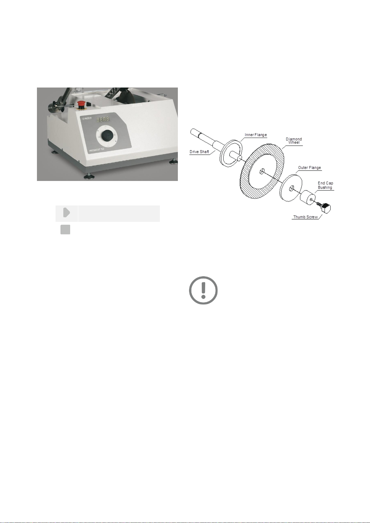
Mounting of Cutting Wheel
Remove Thumb Screw, End Bushing and Outer Flange
from Drive Shaft.
Install wheel on Drive Shaft against Inner Flange relieved
surface.
Slip on Outer Flange and End cap Bushing, then hand
tighten Thumb Screw to complete installation.
Mounting of Abrasive/Diamond/CBN Wheel
Flanges provide support for the wafering blades. Failure to
provide adequate flange support may result in curved cuts
and damaged blades.
NOTE
Before reinstallation of a wheel, the Cap
Bushing, Screw and Flanges should be
cleaned in a mild detergent solution to
remove adherent particles from previous
sawing. This will help prevent misalignment
of wheel, which might cause poor-quality
cuts.
15
Blade Dressing
New wheels must be dressed before making sample cuts.
Dressing removes normal smeared matrix metal and exposes
the abrasive grain to assure free cutting. Blade dressing
exposes the abrasive grain to ensure free cutting. New
wafering blades should be dressed several times and older
blades dressed as required based on the specimen material
properties. When cutting metal samples, it may be necessary
to dress after each cut.
Regular dressing of diamond and CBN cut-off wheels is
important to keep a consistent quality of the cuts. A badly
maintained and poorly dressed cut-off wheel requires a higher
cutting pressure and will, therefore, generate more frictional
heat. It may also bend, causing deformed cuts.
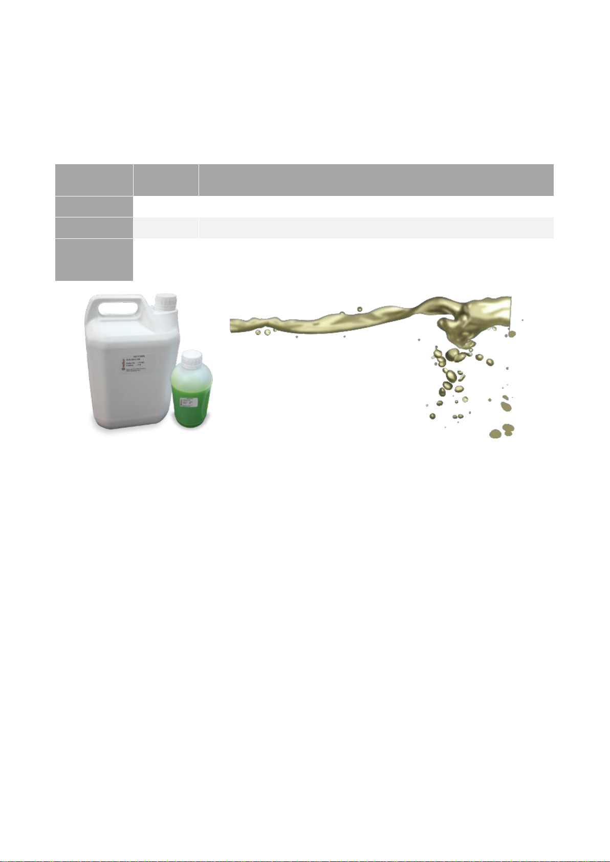
Please fasten the dressing stick to the special sample holder
and mount this sample holder to the equipment as shown in
below picture. Tighten the special sample holder to the main
body of the instrument with the set screws. Start the machine
in low speed. You can do the dressing within the same time
you are doing a cutting operation.
Dressing Unit
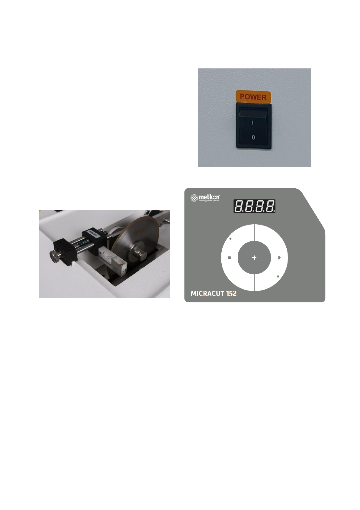
Cutting Operation
Turn on the equipment from the main power switch at
the backside of the machine.
Main Power Switch
The display of the front panel will be lighten up.
Set the disc speed by turning the knob from the front
panel to the desired speed in RPM.
Press the turn-knob to save the disc speed.
Fast speeds tend to damage the specimen surface.
Settings between 500-800 RPM are recommended for
general use.
After the disc speed is set, press the “Start”button and
carefully lower the Specimen Arm onto the wheel to start
cutting.
For safety reasons, shut the transparent cover on top of
the cutting chamber.
Adjust the position of the sample by the help of the
micrometer located at the right side of the equipment.
When the cut is completed, the Cut-Off Switch Arm is
automatically depressed which stops the MICRACUT 152.
16
SERVICE AND MAINTENANCE
Maintenance
The MICRACUT 152 Precision Cutter should be cleaned
periodically to prevent build-up of cutting residue and cutting
fluids. Exterior painted surfaces including the cutting chamber
may be cleaned with non-abrasive household cleaners.
The protective hood and touch screen control panel should
be cleaned with a soft cloth.
Use only “METCOOL II” cutting fluids to obtain maximum
corrosion protection and cooling properties.
Use only “METCOOL-NF” cutting fluid if you continuously cut
reactive metals like copper, brass, cobalt, aluminum, tungsten
carbide, etc… METCOOL-NF has perfect corrosion protection
for the machine when cutting these parts.
The precision of diamond and CBN cut-off wheels and thus
the cut depends on how carefully the following instructions
are observed:
Never expose the cut-off wheel to overload, such as
heavy mechanical load, or heat.
Store the cut-off wheel in a dry place, horizontally on a
plane support, preferably under light pressure.
A clean and dry cut-off wheel does not corrode.
Therefore, clean and dry the cut-off wheel before
storing. If possible, use ordinary detergents for the
cleaning.
When the cutter is not in use for a long time, keep the hood
raised so that the unit dries.
Daily Maintenance
At the end of the working day, please clean the cutting
chamber. After cleaning it is recommended to dry the
clamping devices and the cutting chamber.
Leave the hood open when you are finished with
cleaning.
If the cooling fluid level is low, please add fluid.
After cutting operation please control diamond cutting
wheel and dress the surface of the wheel if necessary.
Recirculation Cooling Tank
Weekly Maintenance
Remove the cooling fluid tank. Drain the cutting fluid
completely and clean all the swarf and particles. Prepare
the new cutting fluid suspension and fill.
Prepare the new cutting fluid suspension in a ratio of 97
% water + 3 % METCOOL II cutting fluid.
Do not add only water, because concentration become
low which may cause corrosion. Add mixture at a ratio of
97% water + 3% METCOOL II cutting fluid. Water
hardness should be 5-20 °dH in German Hardness and
do not contain bacteria and chemical salts.
Monthly Maintenance
The clamping vises need monthly lubrication with a,
water-resistant automotive grease. (Never use grease
containing Molybdenum Disulphide or graphite, which
can impair the clamping ability of the Vise.)
Remove the cooling fluid tank. Drain the cutting fluid
completely, and clean out all the swarf and fine particles.
Prepare anew cutting fluid suspension.

17
Troubleshooting
ERROR
DESCRIPTION
ACTION
The cut-off wheel is not rotating
The hood is left open
Close the hood properly.
Burning remarks on the cutting surface
The cut-off wheel is not compatible
with the cut piece
Use proper cut-off wheel.
See consumables section for the
correct cut-off wheel selection.
High cutting force
Lower the force applied
Insufficient cooling
Check that there is enough cooling
fluid in the tank.
Unwanted burrs on the sample
The cut-off wheel is not compatible
with the cut piece
Use proper cut-off wheel.
See consumables section for the
correct cut-off wheel selection.
High cutting force at the end of cycle
Reduce the cutting force before the
end of the operation
Improper clamping of the sample
Support the sample from both sides.
Cut-off wheel breaks
Incorrect mounting of the cut-off wheel
Check the mounting of the cut-off
wheel and be sure that the nut and
the flange is set properly
The cut-off wheel is not compatible
with the cut piece
Use proper cut-off wheel.
See consumables section for the
correct cut-off wheel selection.
High cutting force
Lower the force applied.
Insufficient cooling
Check that there is enough cooling
fluid in the tank.
The Lexan window is blurred
Insufficient cleaning
Clean the Lexan window with a mild
soapy water (Do not use the cooling
fluid)

18
ACCESSORIES AND CONSUMABLES
Clamping Devices and Accessories
METKON offers a number of special clamping devices and specimen vices for use with our MICRACUT precision cutters. Please
see below, the clamping devices and accessories table, as well as clamping device drawings.
Order No
Specimen Vises for MICRACUT 152
GR 0213
Cutting Table Attachment for manual cutting of extra flat specimens and PCB 's.
GR 0409
Dressing Unit for MICRACUT 152
YM 1590-00
Dressing Stone
GR 0400
Universal Specimen Vise
GR 0401
Specimen vise with double parallel vice for long specimens
GR 0402
Specimen vise for round and mounted specimens, ø 32mm
GR 0403
Specimen vise for irregular shaped specimen
GR 0404
Specimen vise for adhering specimens
GR 0405
Specimen vise for biomedical samples
GR 0406
Swivel arm unit for angular cutting
GR 0430
Specimen vise (teardrop shape) for specimens 18-40mm
GR 0431
Specimen vise (teardrop shape) for specimens 5-20mm
GR 0434
Specimen vise for round cylindrical specimens (up to 40 mm diameter)
GR 0453
Fastener vise for longitudinal sectioning of screws, fasteners, tubes, etc.
from 12 to 45 mm. in length
GR 0410
Set of Flanges, Ø75 mm, suitable for 12.7 and 25.4 mm arbor diameters.
Order No
Spare Part Kit for MICRACUT 152
GR 1960
Recommended Set of Spare Parts, MICRACUT 152
*SWITCH, 1 pc.
*DIGITAL MICROMETER, 0-25, 0.001 mm, 1 pc.
*BELT, 10 mm, 1 pc.
*PULLEY GEAR, Ø12, 1 pc.
*BEARING, 6001, 1 pc.
*SPRING, MICROMETER MOTION, 1 pc.

19
Consumables
Abrasive cut-off wheels
The most commonly used abrasives for the cutting of different materials are SiC and Al2 O3. Silicon carbide is suitable for non-
ferrous metals, whereas Aluminum oxide is preferred for ferrous metals. Hard wheels are used for cutting soft materials while
soft wheels are recommended for cutting harder materials.
Diamond and CBN Cut-off Wheels
Metal bonded wheels are used for cutting brittle materials, such as ceramics or minerals, while resin bonded wheels are used
for ductile materials, such as sintered carbides or composites that contain predominantly hard phases. Several factors are
important for choosing the appropriate wafering blade.
These include:
“High & low concentration metal bonded diamond wheels”, “Diamond size (fine or medium)”, “blade diameter”and “blade
thickness”. The diamond concentration is important because it directly affects the load, which is applied during cutting. For
example, brittle materials such as ceramics require higher effective loads to section, whereas ductile materials such as metals
require more cutting points. The result is that low concentration blades are recommended for sectioning hard brittle materials
such as ceramics and high concentration blades are recommended for ductile materials containing a large fraction of metal or
plastic.
CBN wheels are usually used for cutting very hard metals.
Order No
CODE
DESCRIPTION
18-150
TRENO-HP
Ø150 mm, for Non-Ferrous Metals, Stainless Steels, 10 pcs/pack
18-151
TRENO-MP
Ø150 mm, for Medium and Hardened Steels, 10 pcs/pack
Order No
CODE
DESCRIPTION
19-100
DIMOS
Ø100 mm, Diamond Cut-off wheels (Metal Bonded, high conc.)
19-125
DIMOS
Ø125 mm, Diamond Cut-off wheels (Metal Bonded, high conc.)
19-130
DIMOS
Ø125 mm, Diamond Cut-off wheels (Metal Bonded, low conc.)
19-126
DIMOS
Ø125 mm, Diamond Cut-off wheels (Resin Bonded, high conc.)
19-150
DIMOS
Ø150 mm, Diamond Cut-off wheel (Metal Bonded, High Concentration)
19-157
DIMOS
Ø150 mm, Diamond Cut-off wheel (Metal Bonded, Low Concentration)
19-151
DIMOS
Ø150 mm, Diamond Cut-off wheel (Resin Bonded, High Concentration)
19-127
CBN
Ø125 mm, CBN Cut-off wheels (Metal Bonded, high conc.)
19-152
CBN
Ø150 mm, CBN Cut-off wheels (Metal Bonded, high conc.)
20
Cutting Fluid
Cutting fluid is one of the most important thing to protect sample surface and the machine. Its function is to reduce heat
generation between cut-off wheel and specimen surface during cutting operation. Second function is to prevent corrosion from
specimen surface and the machine parts. METCOOL II has special anti-corrosion additives as well as perfect cooling properties.
It is nature friendly, boron-free and anti-bacterial. METCOOL-NF provides perfect corrosion protection when cutting reactive
metals like copper, brass, cobalt, aluminum, tungsten carbide, etc... Mixing ratio is 95% water + 5% METCOOL II.
Order No
CODE
DESCRIPTION
19-902
METCOOL
Nature Friendly Soluble Oil, 5 lt.
19-905
METCOOL II
Nature Friendly Soluble Oil, 1 lt.
19-906
METCOOL-NF
Nature Friendly Soluble Oil, 5 lt.
Perfect corrosion protection for reactive metals like copper, brass, cobalt, aluminum,
tungsten carbide, etc.
Table of contents
Other Metkon Cutter manuals


 operating instructions")


