nozzle holder are replaced;
• Do not remove or short-circuit the safety devices.
• Use only original spare parts.
• Always replace any damaged parts of the machine
with original materials.
• Do not run the machine without its housings. This
would be dangerous to the operator and anyone else
in the work area, and would prevent the machine from
being cooled properly.
2.4 EXPLANATION OF TECHNICAL SPECIFICATIONS
This machine is manufactured according to the following
international standards: IEC 60974.1 - IEC 60974.3 - IEC
60974.7 - IEC 60974.10 CL. A - IEC 61000-3-11 - IEC
61000-3-12 (61000-3-12 (see note 2).
N°. Serial number.
Must be indicated on any type of request
regarding the device.
Three-phase static transformer-rectifier fre-
quency converter.
Downslope.
Suitable for plasma cutting.
TORCH TYPE Type of torch that may be used with this
machine to form a safe system.
U0. Secondary open-circuit voltage.
X. Duty cycle percentage.
The duty cycle expresses the percentage of
10 minutes during which the welding machine
may run at a certain current I2and voltage
U2without overheating.
I2. Cutting current.
Art. 359: 60A @ 208/220/230/400/440V
Art. 361: a) 100A @ 400/440V
b) 80A @ 208/220/230V
U2Secondary conventional voltage with welding
current I2This voltage depends on the
distance between the contact tip and the
workpiece.
If this distance increases, the cutting vol
tage also increases and the duty cycle
X% may decrease.
U1. Rated supply voltage for 208/220/230V -
400/440V with automatic voltage change.
3~ 50/60Hz 50- or 60-Hz three-phase power supply
I1Max Max. absorbed current at the corresponding
current I2and voltage U2.
I1eff This is the maximum value of the actual cur-
rent absorbed, considering the duty cycle.
This value usually corresponds to the capa-
city of the fuse (delayed type) to be used as
a protection for the equipment.
IP23 S. Protection rating for the housing.
Grade 3as the second digit means that this
equipment may be stored, but it is not
suitable for use outdoors in the rain, unless
it is protected.
. Suitable for use in high-risk environments.
NOTE:
1- The machine has also been designed for use in envi-
ronments with a pollution rating of 1. (See IEC 60664).
2- This equipment complies with IEC 61000-3-12 provided
S
that the maximum permissible system impedance Zmax
is less than or equal to 0,146 (Art. 359)-0,088 (Art. 361)
at the interface point between the user's supply and the
public system. It is the responsibility of the installer or
user of the equipment to ensure, by consultation with the
distribution network operator if necessary, that the equip-
ment is connected only to a supply with maximum per-
missible system impedance Zmax less than or equal to
0,146 (Art. 359)-0,088 (Art. 361).
2.5 START-UP
The machine must be installed by qualified personnel.
All connections must be made in compliance with
current safety standards and full observance of safety
regulations (see CEI 26-23 - IEC TS 62081).
Connect the air supply to the fitting B.
If the air supply comes from a pressure regulator of a
compressor or centralized system, the regulator must be
set to an output pressure of no more than 8 bar (0.8 Mpa).
If the air supply comes from a compressed air cylinder,
the cylinder must be equipped with a pressure regulator.
Never connect a compressed air cylinder directly to the
regulator on the machine! The pressure could exceed
the capacity of the regulator, which might explode!
Connect the power cord A: the yellow-green cable wire
must be connected to an efficient grounding socket on
the system. The remaining wires must be connected to
the power supply line by means of a switch placed as
close as possible to the cutting area, to allow it to be shut
off quickly in case of emergency.
The capacity of the cut-out switch or fuses installed in
series with the switch must be equal to the current I1eff.
absorbed by the machine.
The absorbed current I1eff. may be determined by rea-
ding the technical specifications shown on the machine
under the available supply voltage U1.
Any extension cords must be sized appropriately for the
absorbed current I1max.
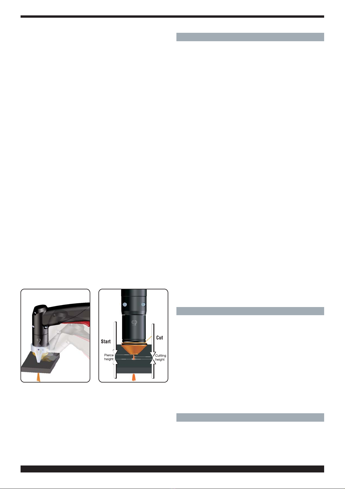
3 USE
Make sure the trigger has not been pressed.
Turn the machine on using the switch C. The warning
lamp Vwill light to indicate that the machine is on.
By pressing for an instant the welding torch button com-
pressed air flow is opened. Under this condition set the
pressure shown by the pressure gauge F, at 5 bar (0.5
MPa) for 6 m long torches and 0.55 bar (0.55 MPa) for 12
m long torches by means of the reducer knob E, and
then lock the knob by pushing it down.
Connect the grounding clamp to the workpiece.
The cutting circuit must not be deliberately placed in
direct or indirect contact with the protective wire except
in the workpiece.
If the workpiece is deliberately grounded using the pro-
tective conductor, the connection must be as direct as
possible and use a wire of at least the same size as the
cutting current return wire, and connected to the work-
piece at the same point as the return wire using the return
wire clamp or a second grounding clamp placed in the
immediate vicinity. Every precaution must be taken to
avoid stray currents.
9