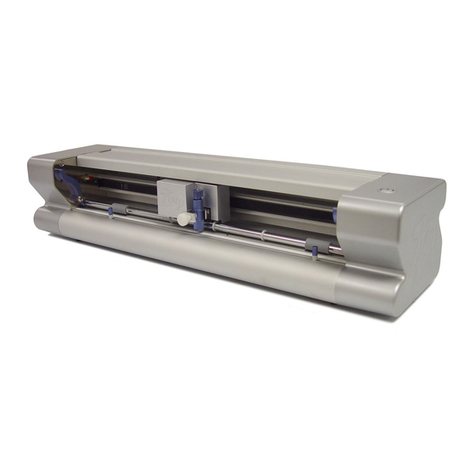
THERMACUT EX-TRACK User manual

PORTABLE CNC CUTTING SYSTEM
Operator Manual
EX-0-902-001
N-22063
Revision Date: December 01, 2019
Revision Number: 01.3
Language: English

EX-TRACK®
Operator Manual, Revision T-12
Foreword
Thank you for purchasing the Thermacut®EX-TRACK®CNC Cutting System, the system is available
with a oxy fuel cutting torch. The system has been designed and manufactured to deliver: reliability,
dimensional accuracy and reproducible profile part cutting. The system is easy to operate and
maintain, read this instruction manual before proceeding, be aware, there is a potential for danger
upon installation, operating or maintaining the system.
It is the responsibility of the operator/user to ensure the safe use/handling of the system, refer to
Thermacut’s terms and conditions of sale for specific responsibilities and limitations on liability.
Information in this document is subject to change without notice. The manual is for the convenience
and use of the Thermacut®EX-TRACK®CNC Cutting System purchaser, it is not a contract or
obligation on the part of Thermacut®“The Cutting Company”.
Safety precautions
This instruction manual describes the correct, effective and safe use of the system. All personnel
involved in the use or maintenance of the system should read this instruction manual thoroughly
and familiarize themselves in the correct and safe method of operation. A copy of this instruction
manual should be kept with the system at all times for easy reference.

EX-TRACK®
Operator Manual, Revision T-1 3
Foreword........................................................................................................................ 2
Safety precautions ........................................................................................................ 2
1. SAFETY INSTRUCTIONS ............................................................................9
1.1. General system safety precautions .................................................................. 12
1.1.1. System safety .................................................................................................... 12
1.1.2. Personal protective equipment ...................................................................... 12
1.1.3. Safety precautions prior to handling and operation ................................... 13
1.2. Plasma/oxy fuel gas cutting safety awareness................................................. 14
1.2.1. Prevention of fire and explosion..................................................................... 14
1.2.2. Safe use of gas pressure regulators .............................................................. 14
1.2.3. Gas cylinder handling and storage ............................................................... 14
1.2.4. Oxy fuel gas hose safety precautions ........................................................... 14
1.2.5. Risk of fire ......................................................................................................... 15
1.2.6. Risk of burn injury ........................................................................................... 15
1.2.7. Safety in the workplace ................................................................................... 16
2. LOCATION OF WARNING AND SAFETY LABELS .....................................18
3. SPECIFICATION .......................................................................................22
3.1. System overview.................................................................................................. 23
3.1.1. Main features .................................................................................................... 23
3.1.2. Range of application........................................................................................ 23
3.2. System parts description .................................................................................... 23
3.3. Technical parameters.......................................................................................... 24
3.4. Torch height controller........................................................................................ 24
3.5. Gas supply............................................................................................................ 25
4. UNPACKING AND ASSEMBLY..................................................................26
4.1. Packing list............................................................................................................ 27
4.2. System assembly ................................................................................................. 28
4.2.1. Parts check ........................................................................................................ 28
4.2.2. Fitting the main unit on to the longitudinal guide rail................................. 28
4.2.3. Fitting the transverse guide rail...................................................................... 29
4.2.4. Fitting the torch height controller .................................................................. 29
4.2.5. Gas supply connection.................................................................................... 30
4.2.6. Electrical connection ....................................................................................... 30
5. CUTTING PROCESS .................................................................................32
5.1. Prior to operating the system............................................................................. 33
INDEX

EX-TRACK®
Operator Manual, Revision T-14
5.1.1. Input voltage settings ...................................................................................... 33
5.1.2. EX-TRACK®placement ..................................................................................... 33
5.1.3. Oxy fuel nozzle choice..................................................................................... 33
5.1.4. Regulated gas supply ...................................................................................... 33
5.1.5. Oxy fuel cut charts............................................................................................ 33
5.1.6. Pre-ignition check............................................................................................. 34
5.2. Ignition and flame adjustment - oxy propane cutting .................................... 34
5.3. Cut quality ............................................................................................................ 35
5.4. Preheat time ......................................................................................................... 35
5.5. Torch operation.................................................................................................... 35
5.6. Flashback and backfire prevention................................................................... 36
5.6.1. Flashback prevention ..................................................................................... 36
5.6.2. Backfire prevention ......................................................................................... 36
6. SYSTEM OPERATION...............................................................................38
6.1. Oxy fuel cutting (prior to operation) ................................................................. 39
6.2. Plasma arc cutting (prior to operation)............................................................. 40
7. MAINTENANCE .......................................................................................41
7.1. Cleaning the system............................................................................................ 42
7.2. System lubrication............................................................................................... 42
7.3. Drive motor adjustment...................................................................................... 42
7.4. Oxy fuel nozzle maintenance............................................................................. 42
8. CIRCUIT DIAGRAM ..................................................................................43
8.1. Plasma interface................................................................................................... 44
9. OPERATION.............................................................................................45
9.1. Control panel functions ...................................................................................... 48
9.2. CNC system functions......................................................................................... 48
9.3. System main menu .............................................................................................. 49
9.3.1. Menu features................................................................................................... 49
9.3.2. Main function F-key menu............................................................................... 50
9.4. Automatic function.............................................................................................. 50
9.4.1. Interfaces and inputs ....................................................................................... 51
9.4.1.1. Speed ............................................................................................................. 51
9.4.1.2. Prog, pierce, kerf .......................................................................................... 51
9.4.1.3. Work mode - running status ....................................................................... 51
9.4.1.4. Input and output signals ............................................................................. 51
9.4.1.5. System parameters display ......................................................................... 51
9.4.1.6. System coordinates display ......................................................................... 52
9.4.1.7. Zoom function [key 1]................................................................................... 52
9.4.1.8. Return [key 2]................................................................................................. 52

EX-TRACK®
Operator Manual, Revision T-1 5
9.4.1.9. Dry run [X]...................................................................................................... 52
9.4.1.10. Speed [Y] ..................................................................................................... 53
9.4.2. Auto processing menu [MAIN MENU → F1 (AUTO)] .................................. 53
9.4.2.1. Pierce point [F1 (SECTION)] ........................................................................ 53
9.4.2.2. Manual mode [F2 (MANUAL)] ..................................................................... 53
9.4.2.3. Break point [F3 (BRK)]................................................................................... 53
9.4.2.4. Graphics display [F4].................................................................................... 54
9.4.2.5. Kerf [F5].......................................................................................................... 54
9.4.2.6. More [F6]........................................................................................................ 54
9.4.2.6.1. [F1 OUTLINE] PERIMETER FUNCTION ................................................... 55
9.4.2.6.2. Rotate (re-orientation) [F3] ....................................................................... 55
9.4.2.6.2.1. Re-orientation angle processing .......................................................... 55
9.4.2.6.3. Mirror [F4]................................................................................................... 56
9.4.2.6.4. Scale [F5]..................................................................................................... 56
9.4.2.6.5. Nest [F6]...................................................................................................... 56
9.4.2.6.6. Tabbing - bridge function [F7 BREAK] .................................................... 57
9.4.2.7. Return [F7]...................................................................................................... 57
9.5. Automatic program mode.................................................................................. 57
9.5.1. Cutting speed................................................................................................... 58
9.5.2. Process start point ............................................................................................ 58
9.5.3. Active key functions when running a program............................................. 58
9.5.4. Active key functions in pause mode .............................................................. 59
9.5.5. Select program................................................................................................. 61
9.5.6. Edge start cutting............................................................................................. 61
9. 6. Manual mode...................................................................................................... 62
9.6.1. Manually controlled functions ........................................................................ 62
9.6.1.1. [↑] [↓] [←] [→] [UP] [DOWN] [LEFT] [RIGHT] directional control keys [G]63
9.6.1.2. Mode switching [F1] ..................................................................................... 63
9.6.1.3. Step [F2] ......................................................................................................... 63
9.6.1.4. More [F3]........................................................................................................ 63
9.6.1.4.1. P-START [F3] a P-END [F4] ........................................................................ 64
9.6.1.4.2. Coordinates settings [F5].......................................................................... 64
9.6.1.4.3. Origin [F7]................................................................................................... 64
9.6.1.5. Mach-0 [F4].................................................................................................... 64
9.6.1.6. Rapid [F5]....................................................................................................... 64
9.6.1.7. Prog-0 [F6] ..................................................................................................... 64
9.6.1.8. Return [F7] ..................................................................................................... 64
9.7. Editing function ................................................................................................... 65
9.7.1 Edit function ...................................................................................................... 65
9.7.1.1. New [F1] ......................................................................................................... 65
9.7.1.2. Load [F2] ........................................................................................................ 65
9.7.1.3. Save [F3] ........................................................................................................ 66
9.7.1.4. Delete files [F4] ............................................................................................. 66

EX-TRACK®
Operator Manual, Revision T-16
9.7.1.5. Delete line [F5] .............................................................................................. 66
9.7.1.6. USB [F6].......................................................................................................... 66
9.7.1.7. View [F7]......................................................................................................... 66
9.8. Setup [F4 PARAMER] .......................................................................................... 66
9.8.1. Process definition - speed............................................................................... 66
9.8.2. Speed parameters [F1].................................................................................... 67
9.8.3. System parameters .......................................................................................... 68
9.8.4. OXY parameters ............................................................................................... 69
9.9. Plasma parameters.............................................................................................. 70
9.9.1. Control parameters ......................................................................................... 71
9.9.2. THC .................................................................................................................... 73
9.9.3. Save [F7]............................................................................................................ 74
9.9.4. Gallery function ................................................................................................ 74
9.9.5. Graphics library ................................................................................................ 74
9.9.6. Graphics library (shape development).......................................................... 75
9.9.7. Shape check...................................................................................................... 75
9.9.7.1. Inside diameter cut [F1] and [F2] Outside diameter cut.......................... 75
9.9.8. Graphics library (nest function) ...................................................................... 76
9.10. Program function............................................................................................... 76
9.10.1. CNC program symbols (G - codes).............................................................. 76
9.10.2. File types ......................................................................................................... 77
9.10.3. File names....................................................................................................... 77
9.10.4. Units of measurement ................................................................................... 77
9.10.5. Programming ................................................................................................. 77
9.10.6. System axes .................................................................................................... 77
9.10.7. G-codes .......................................................................................................... 78
9.10.8. G92 – program zero point............................................................................. 78
9.10.9. G90 – absolute commands ........................................................................... 78
9.10.10. G91 – incremental commands .................................................................. 78
9.10.11. G20 – imperial mode .................................................................................. 78
9.10.12. G21 – metric mode ...................................................................................... 78
9.10.13. G00 – rapid travel......................................................................................... 79
9.10.14. G01 – linear interpolation (motion in a straight line) .............................. 79
9.10.15. G02- G03 – circular interpolation (motion along a circular arc)............. 79
9.10.16. G04 – pause/dwell ....................................................................................... 79
9.10.17. G40 – kerf off (compensation factor)......................................................... 79
9.10.18. G41 – kerf left ............................................................................................... 80
9.10.19. G42 – kerf right............................................................................................. 80
9.10.20. G28 – return to reference point (zero position)........................................ 80
9.10.21. G22 / G80 – cycle command (loop function) ........................................... 80
9.11. M - codes............................................................................................................ 80
9.11.1. M00 - stop....................................................................................................... 80
9.11.2. M02 – program end ...................................................................................... 80

EX-TRACK®
Operator Manual, Revision T-1 7
9.11.3. M07 – cutting sequence start ....................................................................... 80
9.11.4. M08 – cutting sequence stop ....................................................................... 81
9.11.5. Additional M-codes ....................................................................................... 81
10. FAQ’s Operating the system .................................................................82
10.1. FAQ’s Operating the system............................................................................ 83
10.2. Basic trouble shooting...................................................................................... 85
10.3. Software service instructions - Boot menu..................................................... 92
10.4. Backup and restore parameters...................................................................... 93
10.5. Changing System name text............................................................................ 95
10.6. Hardware service instructions.......................................................................... 95
10.6.1. Replacing main fuse ...................................................................................... 95
11. Warranty terms and conditions.............................................................97
S Mark; ......................................................................................................................... 98
CE Mark;....................................................................................................................... 98
C-Tick Mark;................................................................................................................. 98
12. Certification and compliance symbols..................................................98
Appendix: Graphics library .........................................................................99
Shape 1 ......................................................................................................................101
Shape 2 ......................................................................................................................101
Shape 3 ......................................................................................................................101
Shape 4 ......................................................................................................................102
Shape 5 ......................................................................................................................102
Shape 6 ......................................................................................................................102
Shape 7 ......................................................................................................................103
Shape 8 ......................................................................................................................103
Shape 9 ......................................................................................................................103
Shape 10....................................................................................................................104
Shape 11....................................................................................................................104
Shape 12....................................................................................................................104
Shape 13....................................................................................................................105
Shape 14....................................................................................................................105
Shape 15....................................................................................................................105
Shape 16....................................................................................................................106
Shape 17....................................................................................................................106
Shape 18....................................................................................................................106
Shape 19....................................................................................................................107
Shape 20....................................................................................................................107
Shape 21....................................................................................................................107
Shape 22....................................................................................................................108

EX-TRACK®
Operator Manual, Revision T-18
Shape 23....................................................................................................................108
Shape 24....................................................................................................................108
Shape 25....................................................................................................................109
Shape 26....................................................................................................................109
Shape 27....................................................................................................................109
Shape 28....................................................................................................................110
Shape 29....................................................................................................................110
Shape 30....................................................................................................................110
Shape 31....................................................................................................................111
Shape 32....................................................................................................................111
Shape 33....................................................................................................................111
Shape 34....................................................................................................................112
Shape 35....................................................................................................................112
Shape 36....................................................................................................................112
Shape 37....................................................................................................................113
Shape 38....................................................................................................................113
Shape 39....................................................................................................................113
Shape 40....................................................................................................................114
Shape 41....................................................................................................................114
Shape 42....................................................................................................................114
Shape 43....................................................................................................................115
Shape 44....................................................................................................................115
Shape 45....................................................................................................................115
Shape 46....................................................................................................................116
Shape 47....................................................................................................................116
Shape 48....................................................................................................................116
Shape 49....................................................................................................................117
Shape 50....................................................................................................................117
Notes:.........................................................................................................................118
Revision history: ........................................................................................................119

EX-TRACK®
Operator Manual, Revision T-1 9
SECTION 1.
SAFETY INSTRUCTIONS:
1.1. General system safety precautions ............................................................................... 12
1.1.1. System safety ................................................................................................................. 12
1.1.2. Personal protective equipment ................................................................................... 12
1.1.3. Safety precautions prior to handling and operation ................................................ 13
1.2. Plasma/oxy fuel gas cutting safety awareness.............................................................. 14
1.2.1. Prevention of fire and explosion.................................................................................. 14
1.2.2. Safe use of gas pressure regulators ........................................................................... 14
1.2.3. Gas cylinder handling and storage ............................................................................ 14
1.2.4. Oxy fuel gas hose safety precautions ........................................................................ 14
1.2.5. Risk of fire ...................................................................................................................... 15
1.2.6. Risk of burn injury ........................................................................................................ 15
1.2.7. Safety in the workplace ................................................................................................ 16
1. SAFETY INSTRUCTIONS

EX-TRACK®
Operator Manual, Revision T-110
Safety Instructions
Many accidents are caused by disregard for basic safety rules in the operation, inspection and
maintenance of devices. So carefully read, fully understand, and comply with the safety measures
and precautions described in this instruction manual and on the system before operating,
inspecting, and maintaining the system.
The system safety label categories are as follows:
WARNING
CAUTION
NOTICE SIGNS
This symbol is used as a warning message or a warning label. It is positioned at
places that could cause injury or serious accident.
This symbol is used as a caution message or a caution label. It is positioned at places
that could cause slight injury or system damage. This is also used as a caution for
highly dangerous actions.
This symbol shows system operators and maintenance engineers items that relate
directly to damage of systems and surrounding facilities and equipment.

EX-TRACK®
Operator Manual, Revision T-1 11
Warning symbols
Symbol Title Meaning
General General caution, warning and danger.
Be careful not to get your
fingers caught!
Possible injury to fingers if caught in the insertion
part.
Caution: Electric shock! Possible electric shock under special conditions.
Ground this equipment. Operators must ground the equipment using the
safety grounding terminal on power plug.
Pull out the power plug from
the outlet.
Operators must unplug the power plug from the
outlet when a failure occurs or when there is a
danger of lightning and when performing all
maintenance tasks.
Caution against bursting. Possible bursting of gas system under certain
conditions.
General General warning.
Caution: Hot! Possible injury due to high temperature under
certain conditions.
Caution: Ignition! Possible ignition under certain conditions.

EX-TRACK®
Operator Manual, Revision T-112
1.1. General system safety precautions
1.1.1. System safety
The EX-TRACK®CNC System is fitted with an Emergency Stop or E-Stop Button. This button is used
to isolate the system from the input (120V/220V) power source. It is intended for use in the case
of an accident or emergency. The E-Stop Button is clearly located on the top of the Main Unit, to
operate, press in to isolate the power to the CNC and drive mechanisms, none of the systems
functions can operate. To restore power to the system, lift the E-Stop Button upwards, the screen will
illuminate and all of the systems functions are restored.
1. The system casing is made from cast Aluminium and sheet metal, exercise care when
handling, do not let the system drop from any height, and protect the system from falling
objects.
2. Oxygen and fuel gas fittings and connections should be tightened using a suitable wrench,
perform a leak test and retighten as required.
3. When fixing a nozzle to the oxy fuel torch, tighten the nut with two wrenches. In addition,
avoid; damaging the seat of the nozzle since this may cause flashback.
4. Never disassemble the system other than during maintenance and inspection. Otherwise,
a system malfunction may occur.
5. Never modify the system. Modification can be very dangerous and voids the warranty.
6. Switch the power off when the system is not in use.
7. Never use the system outside in the rain, the system may malfunction, this could result
in serious injury or death.
8. This system is not intended for use with plasma cutting power supplies that utilize high-
frequency (H/F) arc ignition.
1.1.2. Personal protective equipment
1. During operation, ensure that suitable personal protective equipment is used: gloves,
gauntlets, goggles, face shields, safety shoes, and additional equipment as required.
2. Prohibit operation of the system if clothes or hands are wet, in order to prevent electric shock,
electric shock can cause serious injury or death.

EX-TRACK®
Operator Manual, Revision T-1 13
1.1.3. Safety precautions prior to handling and operation
1. Read and understand the content of this instruction manual before operating the system.
2. Before connecting the external power supply to the system, ensure that the system ON/OFF
switch is set to OFF.
3. Before operating, check to confirm correct installation, ensure that the movement of the
mechanism is unrestricted.
4. Prior to operating the system, check the work area for hazards in order to avoid accidents
5. Never move or reposition the system when in use, there is a serious risk of injury from Oxy
fuel flame and plasma arc stream.
6. Keep the rail clean and free from debris, failure to do so can result in damage to the system,
and the machine-guiding track, thus affecting the cut quality.
7. Care should be taken to prevent objects impacting/colliding with the track.
8. Prior to powering up the system, ensure that the OFF Line button is depressed (OFF position).
When the system ON/OFF switch is in the ON position, the OFF Line button should NOT be
illuminated. Failure to do so can result in injury.
9. To reduce the risk of an accident, prohibit the touching of moving parts while the system is
running.
10.DO NOT use the EX-TRACK®for welding purposes the circuit boards will suffer catastrophic
damage!
11.Do not operate the system during an earthquake.
12.Ensure correct connection of the oxygen and fuel gas hoses. Gas fittings/connections are
screw threaded; ensure they are correctly tightened to prevent them becoming loose during
operation.
13.If running the system in oxy fuel mode: when checking the running of system (dry run), ensure
that the preheat oxygen valve and the fuel gas valve are in the OFF position.
14.After cutting, the cutting nozzle, torch and mountings may be hot, wear gloves if handling
these parts.
15.Prevent the power cable and hoses from being trapped or crushed, ensure their free
movement.
16.The EX-TRACK®system is not designed for use where it is mounted on soft ground or
unstable surfaces.
17.Do not leave the system unattended when in use.
18.Hoses should be supported to reduce the risk of accidents/injury.
19.When a fuse frequently blows, to prevent damage to the system or injury to the operator, stop
all use, the cause for the fuse failure requires investigation/repair before commencing work
with the system.

EX-TRACK®
Operator Manual, Revision T-114
1.2. Plasma/oxy fuel gas cutting safety awareness
It is essential that ALL operators of the system are aware of the potential danger/risk associated with
Plasma/Oxy fuel Gas cutting operations. Keep “SAFETY” in mind!
1.2.1. Prevention of fire and explosion
1. Never cut in to pressurized cylinders or hermetically sealed containers. Check for flammable
liquids, gases, vapors and other combustible materials.
2. Ensure there is sufficient ventilation to safely use Oxy fuel gas or plasma cutting processes,
use fume extraction/forced air systems as required.
1.2.2. Safe use of gas pressure regulators
1. Prior to use, perform a visual check on the regulators, look for physical damage to the body/
gauges, check for a sticking pressure indicator, ensure the gauges are clean and dry.
Do not allow pressure regulators to come in to contact with oil or grease, this can lead
to spontaneous combustion.
2. Gradually open the cylinder/manifold valve (manifolds are used on multi-gas delivery
systems) allowing the regulator to be pressurized without causing a sudden violent shock that
can cause damage.
3. Check the pressure gauge dial to ensure the pressure indicator is not sticking, listen for gas
leaks. Do not use damaged or leaking pressure regulators.
4. Do not attempt the repair of pressure regulators. Specialist training and equipment is
required. Serious injury or death can result from tampering with the device.
1.2.3. Gas cylinder handling and storage
1. Never use cylinders that are damaged, have been used as rollers/supports or are leaking gas.
2. Cylinders should be stored/installed away from sources of heat, sparks, molten metal, and
open flame. Kept in an upright position, take measures to prevent them from falling, secure
using chains or other approved methods.
3. Cylinders are to be used for the specified purpose only.
4. Contact the cylinder supplier if there is difficulty in opening/closing the valve. Do not use
force.
1.2.4. Oxy fuel gas hose safety precautions
1. The hoses are color coded, RED for fuel gas and Blue for oxygen, the hose fittings have
dissimilar threads, the fittings on the fuel gas (RED) hose are “Left hand or Anti-clockwise”
threads, the fittings have a small groove machined in to the external surface as an
identification mark. The fittings on the oxygen (BLUE) hose are “Right hand or Clockwise”
threads.

EX-TRACK®
Operator Manual, Revision T-1 15
2. Replace hoses that are showing signs of cracking, leaking, and damage caused by sparks,
heat, open flame, crushed etc.
3. When installing hoses, do not over tighten the fitting.
4. Exercise care when using/transporting hoses.
5. Do not drag the hoses when moving the system.
6. Perform Periodic safety checks to confirm the condition of the hoses, as a minimum the hoses
should be free from signs of damage, age related wear/cracking with no gas leaks from the
hoses or fittings.
7. Where possible use the minimum length of hose between the gas supply point and the
EX-TRACK®, this reduces the risk of excess hose being damaged or causing a trip hazard. A
shorter hose may improve gas flow.
1.2.5. Risk of fire
Prior to cutting, survey the work area and assess the risk of fire. The cutting processes
generate as a minimum hot molten metal and sparks. You are responsible for your own safety
as well as others.
1. The work area should be free from flammable liquids, gases, vapors and other combustible/
flammable materials, ensure that suitable fire extinguishers for use on: Gas/Electrical/Hot
metal fires are suitably located, locate fire buckets with sand/water as necessary.
2. Allow the parent material, profile cut parts and scrap time to cool down before moving them.
3. Never cut in to sealed or open canisters/containers that have been used for gases or
flammable products.
1.2.6. Risk of burn injury
Observe the safety precautions to avoid the risk of a burn injury. The oxy fuel and plasma
cutting processes generate as a minimum hot molten metal, sparks and radiation, the effects
can occur both during and after the cutting process.
1. Do not cut near flammable liquids, gases, vapors or other combustible/flammable materials.
Remove flammable materials from the work area, flying sparks are a source of ignition
2. Never cut into sealed or open canisters/containers that have been used for gases or
flammable products.
3. Do not keep lighters or matches on your person.
4. When operating the EX-TRACK®system, maintain a safe distance from the torch.
5. To minimize the risk of injury, the appropriate Personal Protective Equipment must be worn.

EX-TRACK®
Operator Manual, Revision T-116
6. Oxy fuel cutting, ensure that the nozzle is correctly seated and tightened so as not to damage
the seat/sealing area and prevent “Flashbacks” to the system.
• Whenxinganozzletothetorch,usetwowrenchestoavoiddamagetothetorch.
Over tightening the nozzle will result in the nozzle overheating during the cutting
process, making the nozzle more difficult to remove.
• Damagetothetaperofthenozzlecancause“Flashbacks”.
7. An appropriate method of gas leak detection should be used to check the torch, hoses,
connectors, vales and regulators, a suitable “Flashback Arrestor” should be fitted to reduce
the risk of fire or explosion.
DANGER! DO NOT use oil or grease products on the Oxygen hose/torch/valve/regulator or
connections, spontaneous combustion can cause a fire and lead to an explosion. To prevent
any risk of cross contamination, it is advisable NOT to permit the use of oil or grease on any
of the Oxy fuel supply or delivery components.
8. Check the following prior to igniting the Oxy fuel torch: Ensure that the torch is correctly
seated and fixed in to the torch mount. The appropriate Personal Protective Equipment is to
be worn/used. Check the work area for obstacles, hazardous/flammable materials. Check that
the input and output gas pressures are correct and suitable for the job in hand
9. Appropriate Personal Protective Equipment is to be worn/used when handling the torch,
nozzle, idler wheel locking device, allow adequate time for the system to cool down after
cutting.
1.2.7. Safety in the workplace
1. Use of the cutting processes will produce but not be limited to the following: Sparks, molten
metal, high temperatures, thermal radiation, combustible gases, dust, noise, electric arc light,
electromagnetic radiation. Serious injury can arise from failure to wear/use the appropriate
Personal Protective Equipment during the cutting process. Flammable/highly combustible
gasses are used in the Oxy fuel cutting process, exercise caution, gas leaks or misuse of the
system could result in a fire, explosion and serious injury. Misuse of the cutting system may
cause catastrophic failure of the equipment, resulting in explosive gas leaks/electric shock/
burn injury.
2. The work area should be equipped with the most suitable fire extinguishing equipment,
ensure that the correct extinguishing process is used for fire caused by but not limited
to: gas leaks, electrical fault or hot metal, not all fire extinguishing equipment is suited to
extinguishing all fire types.
3. Implement strict adherence to the relative gas use regulations, cylinder storage, equipment
pressure/condition checks, flashback arrestor checks etc.
4. Keep the work area free from flammable/combustible material. Use of the cutting processes
will produce but not be limited to the following: Sparks, molten metal, high temperatures,
combustible gases, dust, fume extraction should be used in the work area, and this is in
addition to the operator wearing/using Personal Protective Equipment.
5. Prior to starting the cutting process, the operator is to ensure that only authorized personnel
are in the work area.

EX-TRACK®
Operator Manual, Revision T-1 17
ATTENTION: Prior to starting the cutting process, perform a system/equipment check to ensure
there are no gas leaks or visible damage to component parts. If during the cutting process there is
the odor from a gas leak, immediately press the E-Stop button to isolate the electrical power supply,
turn off the gas supply at the torch and then at the point of supply - Cylinder/Manifold. Do not use
the system until it has been checked and deemed safe to use by a suitably qualified person. You are
responsible for your own safety as well as others.

EX-TRACK®
Operator Manual, Revision T-118
2. LOCATION OF WARNING AND SAFETY
LABELS
SECTION 2.
LOCATION OF WARNING AND SAFETY LABELS:
Warning and Safety labels have been affixed to the system for the purpose of hazard awareness
and correct use of the system. Prior to operating the system carefully read the labels and follow the
instructions. Do not remove labels. Always keep the labels legible.
! Caution!
Plasma arc rays can burn eyes and skin
Noise can damage hearing
Flying sparks (arc spray) can cause injury, fire or explosion
Caution! Read operator´s manual
Cutting can cause fire or explosion
Electric shock can kill
Plasma arc can injure
Flying sparks (arc spray) can cause injury, fire or explosion
Hot parts can cause severe burns
Smoke and gases can be hazardous
Caution when cutting around gas cylinders
Do not exceed the recommended duty cycle, this can lead to overheating and cause damage to the system
Magnetic field can affect pacemakers
Plasma cutting can cause interference
Safety sticker

EX-TRACK®
Operator manual, Revision T-1 19
SAFETY
The symbol shown in this section means: !Caution! !Beware!
¡There are possible hazards with this procedure!
When you find this symbol in the manual or on the system,
be cautious, and follow the related instructions to avoid the
hazard.
Follow the safety instructions to avoid danger.
Only qualified persons should install, operate, maintain and
repair the system.
Keep out of reach of children.
Prolonged exposure to noise from plasma cutting/gouging
can cause hearing damage.
• Use approved ear protection when operating the
plasma system.
• Warn others about the dangers of noise.
NOISE CAN DAMAGE HEARING
!Caution!
Arc rays from the cutting/gouging processes produce intense
visible and invisible rays that can burn eyes and skin.
Use protective clothing made from durable, flame-resistant
material, appropriate footwear and hand protection.
• Use face protection (welding helmet or shield) with
the correct shade of filter lens fitted to protect your
eyes and face (see Table 1.1).
• Warn people of the dangers of looking at the arc, use
signs to warn/inform.
PLASMA ARC RAYS CAN BURN EYES AND SKIN
Flying sparks are created during the metal cutting/gouging
processes; the area around the cutting process should be kept
free from flammables.
• Use face shield/safety glasses with side protection.
• Wear flame resistant clothing, footwear and hand
protection.
• Use earplugs/defenders that are flame resistant to
prevent sparks entering the ear and to reduce the
noise level.
FLYING SPARKS (ARC SPRAY) CAN CAUSE INJURY, FIRE OR
EXPLOSION
1
2
Caution!
Readoperator’smanual

EX-TRACK®
Operator Manual, Revision T-120
Touching electrical parts could cause a fatal shock or severe
burns.
• Do not touch live electrical components.
• Wear dry insulated gloves, shoes and protective clothing.
• Insulate yourself from the work and ground using dry
insulating material large enough for the work area.
• The working area should be clean and dry.
• Switch OFF the system for cleaning and maintenance
operations.
• Do not wrap cables around your body.
• Turn OFF the machine when not in use.
ELECTRIC SHOCK CAN KILL
• Periodically check the power supply cable, to insure
that the outer insulation is intact. Replace the power
supply cable immediately if damaged. DO NOT use
the system with bare or exposed wires, this is highly
dangerous.
• Before removing the cover or handling any of the
internal components of the system, wait 5 (FIVE)
minutes to ensure complete discharge of the
capacitors.
• Keep the system in good condition; repair or replace
damaged parts immediately. Maintain the system in
accordance with the manual.
FIRE PREVENTION
• Keep flammable items away from the work area.
• Ensure that there is a fully charged fire extinguisher in the
work area
• Ventilate the work area, check for flammable/combustible
gases, liquids and materials, remove prior to cutting as
they present a fire risk.
EXPLOSION PREVENTION
• Do not cut in areas containing explosives, flammable
gases or vapors.
• Do not place the system on, over, or near combustible
surfaces.
Caution! After cutting, the work piece will be HOT!
• Do not touch hot parts bare handed, wear suitable
hand protection.
• Allow cooling time before handling.
CUTTING CAN CAUSE FIRE OR
EXPLOSION
Flying sparks are created during the metal cutting/gouging
processes; the area should be kept free from flammables.
• Use face shield/safety glasses with side protection.
• Wear flame resistant clothing, footwear and hand
protection.
• Use earplugs/defenders that are flame resistant to
prevent sparks entering the ear and to reduce the
noise level.
FLYING SPARKS (ARC SPRAY)
CAN CAUSE INJURY, FIRE OR
EXPLOSION
The plasma arc is activated immediately after the torch trigger
is depressed.
• Turn off the power before changing the torch
consumables, the plasma arc can burn through skin and
gloves.
• Do not place your hand or hold the work piece near the
cutting path.
• Do not point the torch toward yourself or other persons.
PLASMA ARC CAN INJURE
3
4
5HOT PARTS CAN CAUSE
SEVERE BURNS
• Do not operate the system in areas with an
atmosphere containing high concentrations of dust,
flammable gases or vapors.
• Do not use the system to cut pressurized containers
that have not been de-pressurized, vented and
cleaned.
Table of contents
Other THERMACUT Cutter manuals
