Metra Electronics ELS ASSIGN Touch User manual

Locker Controller ELS ASSIGN Touch Technical Manual

Page 2
Locker Controller ELS ASSIGN Touch Technical Manual
Table of contents
Locker Controller ELS ASSIGN Touch Technical Manual ......................................................................... 3
Product description............................................................................................................................. 3
Basic Parts ........................................................................................................................................... 4
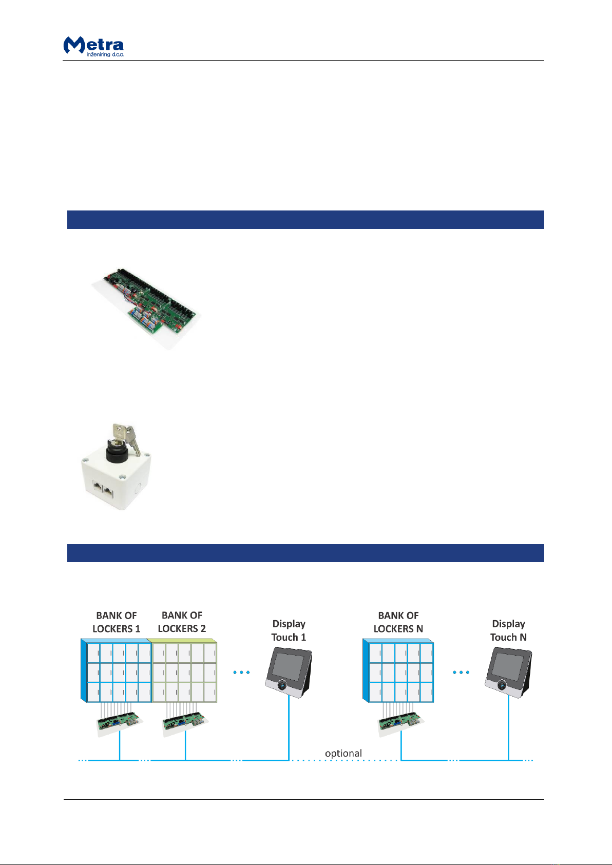
Locker Controller PCB with two extension modules and connecting PCB ..................................... 4
Emergency Open Push-button (optional)....................................................................................... 4
Installation .......................................................................................................................................... 4
Standalone configuration ............................................................................................................... 4
Full network configuration ............................................................................................................. 5
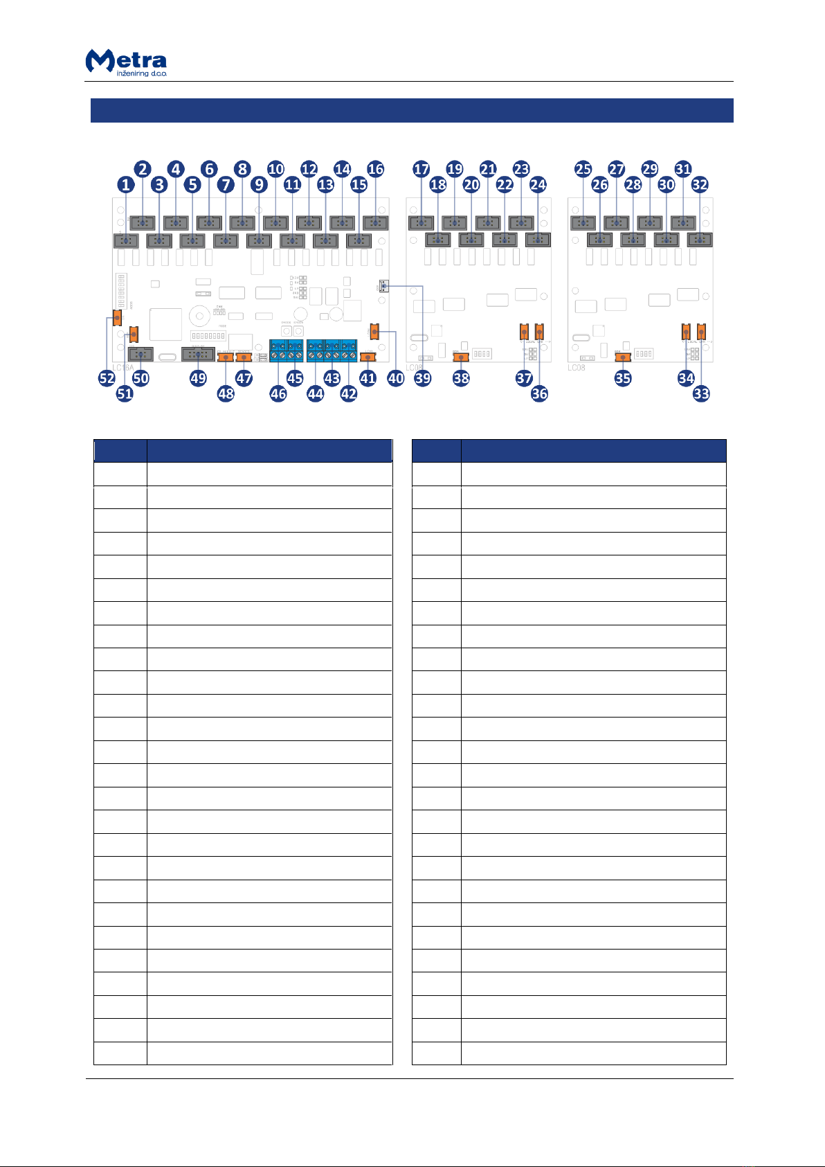
Connections ........................................................................................................................................ 6
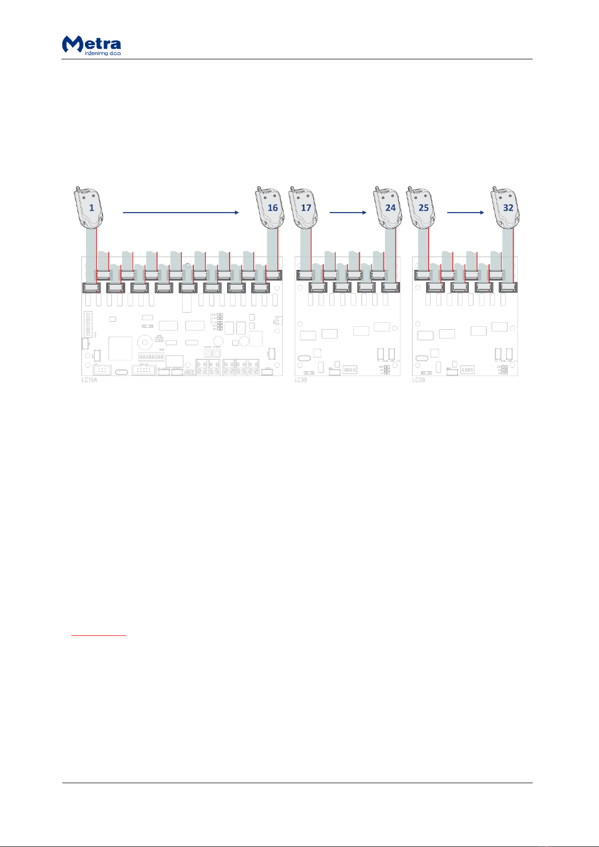
Connecting Locker Extension Modules........................................................................................... 7
Locker Extension Module setting ................................................................................................... 7
Connecting Electronic Locks ........................................................................................................... 8
Power supply connection (Locker Controller without distribution board) .................................... 8
Power supply connection (Locker Controller with distribution board).......................................... 9
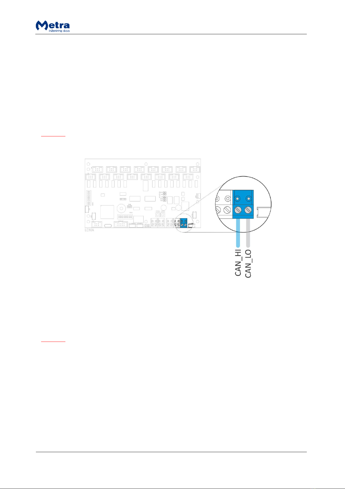
Metra NET Network connection (Locker Controller without distribution board)........................ 10
Metra NET Network connection (Locker Controller with distribution board) ............................. 10
External emergency open pushbutton connection (optional) ..................................................... 11
DIP switch settings ............................................................................................................................ 12
Network address........................................................................................................................... 12
Operating modes .......................................................................................................................... 14
Signalization ...................................................................................................................................... 14
Power-on ...................................................................................................................................... 14
Operation...................................................................................................................................... 15
Network Communication ............................................................................................................. 15
Setting Operational parameters –via Display Touch........................................................................ 16
Setting Operational parameters –via Metra NET Network.............................................................. 16
Emergency Open procedure ............................................................................................................. 16
Internal Emergency open pushbutton.......................................................................................... 17
External Emergency open pushbutton ......................................................................................... 17
Device replacement .......................................................................................................................... 17
Maintenance ..................................................................................................................................... 18
Troubleshooting Guide ..................................................................................................................... 18
Technical data ................................................................................................................................... 18
Appendix ........................................................................................................................................... 18

Page 3
Locker Controller ELS ASSIGN Touch Technical Manual
Manufacturer:
Metra inženiring d.o.o.
IOC Trzin
Špruha 19
SI-1236 Trzin, Slovenia
phone:
fax:
web:
+386 1 56 10 740
+386 1 56 10 744
www.metra.si
System:
Metra ELS ASSIGN –Electronic Locking Systems
Product Group:
Locker Controller
Types:
LC16AEA (Locker Controller 16)
LC16EA (Locker Controller 16 on mounting plate)
LC24EA (Locker Controller 24 on mounting plate)
LC32EA (Locker Controller 32 on mounting plate)
Year of Construction:
2010-2011
Declaration of Conformity:
The Metra ELS ASSIGN products have been developed, designed and
manufactured in accordance with the EU directive for Electromagnetic
Compatibility (2004/108/EC).
Locker Controller ELS ASSIGN Touch Technical Manual [rev.0-240111]
2011 Metra inženiring d.o.o.
All Rights reserved.
No part of this manual may be reproduced in any form or by any means without prior written permission of Metra inženiring d.o.o.
The contents of this manual are subject to change without notice.
All efforts have been made to ensure the accuracy of the contents of this manual, however, should any errors be detected, Metra inženiring would greatly appreciate being informed of
them. Metra inženiring d.o.o. can assume no responsibility for any errors in this manual.
Product description
Metra Locker Controller is used in different Metra Electronic Locking Systems. Device drives and
monitors Metra Electronic Locks. Up to 16 locks can be connected directly to the unit, with the
possibility to add up to two Extension Modules for 8 additional Electronic Locks each. This enables
configurations for up to 16, 24 or 32 locks, which makes the controller adoptable to many locker
layout configurations. As user interface different system specific Metra user interface devices (e.g.
Display RFID/Keypad/Combo/Touch, Reader Terminal, Reader Terminal Basic, etc.) can be used.

Page 4
Locker Controller ELS ASSIGN Touch Technical Manual
Locker Controller also supports emergency and security features. A pushbutton for emergency
opening of all Lockers connected to the Locker Controller (and belonging extension modules) is fitted
on the main electronics board and also an external emergency pushbutton can be connected. In case
of attempt of break-in an Alarm message is distributed over Metra NET Network to Metra user
interface devices and over Metra Network Controller to LAN / WAN and Metra software.
For easier installation on site different configurations of controller & extension module(s) on
mounting plates are supplied.
Basic Parts
Locker Controller PCB with two extension modules and connecting PCB
Emergency Open Push-button (optional)
Emergency Open Push-button is used to initiate Emergency Open procedure
for all Electronic Locks connected to Locker Controller.
Installation
Standalone configuration

Page 5
Locker Controller ELS ASSIGN Touch Technical Manual
ELS Assign can be set up as standalone system, where only Locker Controllers and Displays Touch as
user interfaces are used. Display Touch + up to 16 Locker Controllers form a group. Devices in the
same group must be connected to the same Metra NET Network. Connecting all the groups of
devices into the same Metra NET Network in highly recommended but not required. Operating
parameters are set on the Displays Touch.
Use Metra Network Terminator on all ends of Metra NET Network. For more information see “Metra
NET Network –Installation Manual”.
Full network configuration
In full network configuration all the operating parameters are set in the Metra software. With Metra
software you gain additional functionality:
on-line locker monitoring in real time (e.g. alarm, locker status, etc.)
data analyzing & resource management
user and Master key management
emergency opening (on request or schedule)
remote unlocking from PC (singular locker)
device setup
and more…

Page 6
Locker Controller ELS ASSIGN Touch Technical Manual
Connections
#
description
#
description
1
Electronic Lock 1
27
Electronic Lock 27
2
Electronic Lock 2
28
Electronic Lock 28
3
Electronic Lock 3
29
Electronic Lock 29
4
Electronic Lock 4
30
Electronic Lock 30
5
Electronic Lock 5
31
Electronic Lock 31
6
Electronic Lock 6
32
Electronic Lock 32
7
Electronic Lock 7
33
Local CAN*
8
Electronic Lock 8
34
Local CAN*
9
Electronic Lock 9
35
BDM Loader
10
Electronic Lock 10
36
Local CAN**
11
Electronic Lock 11
37
Local CAN**
12
Electronic Lock 12
38
BDM Loader
13
Electronic Lock 13
39
COM (Not used)
14
Electronic Lock 14
40
Local CAN***
15
Electronic Lock 15
41
Local CAN***
16
Electronic Lock 16
42
Metra NET Network
17
Electronic Lock 17
43
Power****
18
Electronic Lock 18
44
Power****
19
Electronic Lock 19
45
Emergency open pushbutton
20
Electronic Lock 20
46
Coin acceptor (Not used)
21
Electronic Lock 21
47
Reader (Not used)
22
Electronic Lock 22
48
Fingerprint module (Not used)
23
Electronic Lock 23
49
Display (Not used)
24
Electronic Lock 24
50
I2C (Not used)
25
Electronic Lock 25
51
BDM Loader
26
Electronic Lock 26
52
I2C (Not used)

Page 7
Locker Controller ELS ASSIGN Touch Technical Manual
*NOTE: Local CAN connectors and are internally parallel connected.
**NOTE: Local CAN connectors and are internally parallel connected.
***NOTE: Local CAN connectors and are internally parallel connected.
****NOTE: 12V DC Power connectors and are internally parallel connected.
Connecting Locker Extension Modules
When Locker Controller without mounting plate is used connect up to two Extension modules by 6
wire flat cable. There are two equivalent connectors on the main electronics board (LC16A) use the
one which suits your connection best.
When Locker Controller is ordered with mounting plate Extension Modules (LC24_* and LC32_*) are
already connected.
Locker Extension Module setting
The first Locker Extension Module DIP switch (indexes 17-24) and second Locker Extension Module
DIP switch (indexes 25-32) must be set as follows:

Page 8
Locker Controller ELS ASSIGN Touch Technical Manual
Connecting Electronic Locks
Connect Electronic Locks using 6 wire flat cables.
Maximum length of each cable is 20 meters.
Cables from Electronic Locks with lower locker numbers must be connected to lower index
connector. Locker number is increasing from left to right (blue arrows)!
Mind ascending order when numerating lockers. Gaps between numbers are allowed.
EXAMPLE: Most left connector (index 1) is locker number 161, most right connector (index 32) is
locker number 192.
Power supply connection (Locker Controller without distribution board)
Regulated 12 VDC power supply is required for proper operation. Connect as many units as possible
to a single power supply unit. Consult the Technical Specifications section of this document for
current consumption.
There are two internally connected power connectors on the board. You can use one as “Power IN”
and the other as “Power OUT” connector.
Connect 12V DC regulated power supply to designated terminals. The terminals are marked as +12V
for positive connection and GND for ground connection.
WARNING
Mind the polarity! Wrong polarity could result in irreparable damage to the device.
Respect power requirements data! Using unsuitable power supply could result in damage to the
power supply and to the device.

Page 9
Locker Controller ELS ASSIGN Touch Technical Manual
Power supply connection (Locker Controller with distribution board)
Regulated 12 VDC power supply is required for proper operation. Connect as many units as possible
to a single power supply unit. Consult the Technical Specifications section of this document for
current consumption.
Connect 12V DC regulated power supply to designated terminals. The terminals are marked as +12V
for positive connection and GND for ground connection.
WARNING
Mind the polarity! Wrong polarity could result in irreparable damage to the device.
Respect power requirements data! Using unsuitable power supply could result in damage to the
power supply and to the device.

Page 10
Locker Controller ELS ASSIGN Touch Technical Manual
Metra NET Network connection (Locker Controller without distribution board)
The Metra NET Network connection provides for operational functionality of the Locker Controller.
Different devices in parallel can be connected to the Metra Network Controller by a single unshielded
twisted pair (UTP) cable. Total length of the twisted pair cable is limited to 1 km. One Network Line
Terminator must be connected at the far end of the network cable. See also “Metra NET Network –
Installation Manual” for different wiring schemes.
Connect the twisted pair network cable to designated terminals. The terminals are marked as CANLO
for network low signal and CANHI for network high signal.
NOTE
Mind the polarity of the network connection!
Metra NET Network connection (Locker Controller with distribution board)
Connect the twisted pair network cable to designated terminals. The terminals are marked as CANL
for network low signal and CANH for network high signal.
NOTE
Mind the polarity of the network connection!

Page 11
Locker Controller ELS ASSIGN Touch Technical Manual
External emergency open pushbutton connection (optional)
Connect the blue and blue/white wires of the UTP cable from the Emergency open pushbutton to
designated terminals as shown in the schematic.

Page 12
Locker Controller ELS ASSIGN Touch Technical Manual
DIP switch settings
#
description
#
description
1
Emergency open pushbutton
3
Network Address DIP switch
2
Parameters request button
4
Operating Mode DIP Switch (Not used)
To change between different pins positions, use a small flat headed screwdriver or similar object to
push DIP switch pins to desired position.
STANDALONE CONFIGURATION: After each address change power off and back on the device for the
new settings to take effect.
FULL NETWORK CONFIGURATION: After each address change power off and back on the device for
the new settings to take effect. Operating parameters are obtained through the Metra NET Network.
The server, Display Touch and ELS Assign application on the display Touch must be set up and
running for that purpose. To obtain operating parameters, press the PARAMETERS REQUEST
button.
NOTE
Network based functionality will be present only if the server and Display Touch are running and the
Locker Controller has been properly configured.
Network address
After installation is complete, the device’s network address must be set by changing the Network
Address DIP Switch pins positions.

Page 13
Locker Controller ELS ASSIGN Touch Technical Manual
NOTE
Each Metra device must have different address setting.
Switch #1 must be set to OFF (switch down).
Look up the code for desired network address in the coding table. Set switches #2 through #8 to
indicated positions, where:
0 indicates the corresponding switch is in OFF position (switch down)
1 indicates the corresponding switch is in ON position (switch up)
Coding table:
switch positions
address
switch positions
address
2
3
4
5
6
7
8
2
3
4
5
6
7
8
0
0
0
0
0
0
0
1
0
1
1
0
0
1
0
51
0
0
0
0
0
0
1
2
0
1
1
0
0
1
1
52
0
0
0
0
0
1
0
3
0
1
1
0
1
0
0
53
0
0
0
0
0
1
1
4
0
1
1
0
1
0
1
54
0
0
0
0
1
0
0
5
0
1
1
0
1
1
0
55
0
0
0
0
1
0
1
6
0
1
1
0
1
1
1
56
0
0
0
0
1
1
0
7
0
1
1
1
0
0
0
57
0
0
0
0
1
1
1
8
0
1
1
1
0
0
1
58
0
0
0
1
0
0
0
9
0
1
1
1
0
1
0
59
0
0
0
1
0
0
1
10
0
1
1
1
0
1
1
60
0
0
0
1
0
1
0
11
0
1
1
1
1
0
0
61
0
0
0
1
0
1
1
12
0
1
1
1
1
0
1
62
0
0
0
1
1
0
0
13
0
1
1
1
1
1
0
63
0
0
0
1
1
0
1
14
0
1
1
1
1
1
1
64
0
0
0
1
1
1
0
15
1
0
0
0
0
0
0
65
0
0
0
1
1
1
1
16
1
0
0
0
0
0
1
66
0
0
1
0
0
0
0
17
1
0
0
0
0
1
0
67
0
0
1
0
0
0
1
18
1
0
0
0
0
1
1
68
0
0
1
0
0
1
0
19
1
0
0
0
1
0
0
69
0
0
1
0
0
1
1
20
1
0
0
0
1
0
1
70
0
0
1
0
1
0
0
21
1
0
0
0
1
1
0
71
0
0
1
0
1
0
1
22
1
0
0
0
1
1
1
72
0
0
1
0
1
1
0
23
1
0
0
1
0
0
0
73
0
0
1
0
1
1
1
24
1
0
0
1
0
0
1
74
0
0
1
1
0
0
0
25
1
0
0
1
0
1
0
75
0
0
1
1
0
0
1
26
1
0
0
1
0
1
1
76
0
0
1
1
0
1
0
27
1
0
0
1
1
0
0
77
0
0
1
1
0
1
1
28
1
0
0
1
1
0
1
78
0
0
1
1
1
0
0
29
1
0
0
1
1
1
0
79
0
0
1
1
1
0
1
30
1
0
0
1
1
1
1
80
0
0
1
1
1
1
0
31
1
0
1
0
0
0
0
81
0
0
1
1
1
1
1
32
1
0
1
0
0
0
1
82
0
1
0
0
0
0
0
33
1
0
1
0
0
1
0
83
0
1
0
0
0
0
1
34
1
0
1
0
0
1
1
84
0
1
0
0
0
1
0
35
1
0
1
0
1
0
0
85
0
1
0
0
0
1
1
36
1
0
1
0
1
0
1
86
0
1
0
0
1
0
0
37
1
0
1
0
1
1
0
87
0
1
0
0
1
0
1
38
1
0
1
0
1
1
1
88
0
1
0
0
1
1
0
39
1
0
1
1
0
0
0
89

Page 14
Locker Controller ELS ASSIGN Touch Technical Manual
0
1
0
0
1
1
1
40
1
0
1
1
0
0
1
90
0
1
0
1
0
0
0
41
1
0
1
1
0
1
0
91
0
1
0
1
0
0
1
42
1
0
1
1
0
1
1
92
0
1
0
1
0
1
0
43
1
0
1
1
1
0
0
93
0
1
0
1
0
1
1
44
1
0
1
1
1
0
1
94
0
1
0
1
1
0
0
45
1
0
1
1
1
1
0
95
0
1
0
1
1
0
1
46
1
0
1
1
1
1
1
96
0
1
0
1
1
1
0
47
1
1
0
0
0
0
0
97
0
1
0
1
1
1
1
48
1
1
0
0
0
0
1
98
0
1
1
0
0
0
0
49
1
1
0
0
0
1
0
99
0
1
1
0
0
0
1
50
Operating modes
Operating Mode DIP Switch is not used in this type of ELS ASSIGN system. Switches #1 through #8 on
the Operating Mode DIP Switch must be set to OFF (switch down).
Signalization
Power-on
When power is applied the following LEDs are on:
Yellow LED on Locker Controller (12VDC present)
Green LED on Locker Controller (5VDC regulated on board active)
Yellow LED on Extension Module(s) (12VDC present)
Green LED on Extension Module(s) (5VDC present)
Green LED on distribution board (12VDC present)

Page 15
Locker Controller ELS ASSIGN Touch Technical Manual
Operation
Each Locker Controller and Locker Extension Module has a blinking green LED operating indicator. All
these signals are under software control indicating that the device is running.
Network Communication
Network communication (Metra NET) is signalled on the Locker Controller by four LEDs:
Left Green LED is on when the Locker Controller is receiving data packets from Extension
Module(s).
Left Red LED is on when the Locker Controller is transmitting data packets to Extension
Module(s).
Right Green LED is on when the Locker Controller is receiving data packets from Metra NET
Network.

Page 16
Locker Controller ELS ASSIGN Touch Technical Manual
Right Red LED is on when the Locker Controller is transmitting data packets to Metra NET
Network.
Setting Operational parameters –via Display Touch
REQUIREMENTS:
Metra Displays Touch must be connected to Metra NET Network, turned ON and PC application
must be running.
Each Locker Controller must have set its unique Metra NET Network address –ID.
PROCEDURE:
Set Locker Controllers Network adresses –IDs on Displays Touch. See “ELS ASSIGN Touch SW –
System Setup Manual”.
If correct Metra NET Network address is set on the Locker Controller and Locker Controller is
added in the ELS Assign PC application it is detected automatically.
Setting Operational parameters –via Metra NET Network
REQUIREMENTS:
Metra Network Controller must be connected to Metra NET Network.
Metra server must be running and all hardware added in Metra software.
Metra Displays Touch must be connected to Metra NET Network, turned ON and PC application
must be running.
Each Locker Controller must have set its unique Metra NET Network address –ID.
PROCEDURE:
Set Locker Controllers Network adresses –IDs on Displays Touch. See “ELS ASSIGN Touch SW –
System Setup Manual”.
By pressing the PARAMETERS REQUEST button on each Locker Controller you trigger the request
for operating parameters.
Operating parameters are downloaded to the Displays Touch.
Check if correct operating parameters were downloaded.
Emergency Open procedure
Locker Controller features an Emergency Open procedure, which unlocks all Electronic Locks
connected to the Locker Controller and to all of the attached Locker Extension Modules. Locks are
unlocked one by one, starting at the lock connected to the leftmost connector (position #1).

Page 17
Locker Controller ELS ASSIGN Touch Technical Manual
Internal Emergency open pushbutton
STEP 1: Press the Emergency open pushbutton. All
lockers connected to the Locker Controller start to
unlock and open one after another.
External Emergency open pushbutton
STEP 1: Turn the key on emergency open pushbutton
clockwise to initiate emergency opening of all Lockers.
All lockers connected to the Locker Controller start to
unlock and open one after another.
Device replacement
This chapter describes Locker Controller replacement procedure. The problem should be identified
before any repairing is tried.
STEP 1: Disconnect the power supply.
NOTE
Disconnect the adapter not the wires fixed on the Locker Controller board to avoid short circuit.
STEP 2: Open the Locker Controller Box/Locker (see Locker manufacturer's documentation).
STEP 3: Disconnect all cables and mark their exact position.
STEP 4: On the new Locker Controller set the same network address.
STEP 5: Replace the Locker Controller with a new one.
STEP 6: Reconnect all cables exactly the same as they were connected previously.
STEP 7: Connect the power supply.

Page 18
Locker Controller ELS ASSIGN Touch Technical Manual
STEP 8: Close the Locker Controller Box/Locker (see Locker manufacturer's documentation).
Maintenance
No special maintenance is needed.
The maintenance people should check the device operation at least once a year.
NOTE
Direct spraying or splashing water can cause damage to Locker Controller or Electric Locks!
Troubleshooting Guide
trouble
explanation / solution
Locker door closed while locking and nothing happens.
Adjust the door strike. Check the Electric Lock. Replace
the Electric Lock if necessary.
The Locker door not ejected when unlocked.
Adjust the door strike.
Technical data
Operating voltage
12V DC regulated (11.5 –15V DC tolerated)
Current consumption
PCB: 0.65 A peak, 0.45 A average
PCB with two extension modules: 2 A peak, 1 A average
Operating temperature range
0 to +50 °C
Audio signal
integrated piezoelectric beeper
Buffer capacity
40 records
Electronic Lock Interface
Up to 16/24/32 El. Locks, 6 wire flat cable, max. length 20m
Dimensions in mm (w/h/l)
100/20/179 main electronics
100/20/89 extension board
171/5/380 mounting plate
Connections
Power, Metra NET Network, Display, Coin acceptor, external
Emergency open push-button,
Appendix
1
Physical dimensions
Locker Controller
Locker Controller Extension Module

Page 19
Locker Controller ELS ASSIGN Touch Technical Manual
2
Physical dimensions
Mounting rails
3
Physical dimensions
Mounting plate
4
Network schematic
5
Device configuration example

Appendix 1Locker Controller ELS ASSIGN Touch
Physical dimensions
Locker Controller
Locker Controller Extension Module
1 2 53 4 6 7 8
1 2 53 4 6 7 8
19179
100
7.5
15
8.5
17
7.5
26.5
8.5
37.5 36
75.5
84
5
1 2 3 4
11
89
16
39.5 44.5
8.5
100
7.5
8.5
43.5
4.5
30.5 26
7.5
80
Table of contents
Other Metra Electronics Indoor Furnishing manuals
Popular Indoor Furnishing manuals by other brands

BLACK RED WHITE
BLACK RED WHITE LOFT B156-SZF1W1S/60 Assembly

Teknion
Teknion Marini Adjustment features & instructions

Arthauss Furniture
Arthauss Furniture CARINI Ca12 Assembly instructions

VINNOVA
VINNOVA 701648 manual

PHI VILLA
PHI VILLA E02GF081 Use and care guide

Moon Valley
Moon Valley M-1500 Assembly instructions

PG BISON
PG BISON KINETIC FLATPAX RANGE WALL CABINET Assembly guide

Allen + Roth
Allen + Roth RECTANGULAR TABLE 1121 manual

Vivo
Vivo DESK-V100M instruction manual

Bush Business Furniture
Bush Business Furniture AC99850 manual

Home Decorators Collection
Home Decorators Collection BOLINGBROOK D13106-LV-B Use and care guide

Portable Partitions
Portable Partitions MP10 instructions