Metreel MET-TRACK Installation and operating instructions

Tel:
+44 (0)115 9327010
Fax:
+44 (0)115 9306263
Email:
sales@metreel.co.uk
Website:
www.metreel.co.uk
MET-TRACK®Foldaway Rigid Rail
Anchor Systems
Installation & Maintenance Instructions

Foldaway Rigid Rail Anchor System
Installation & Maintenance Instructions
Document Ref. I&M175-0519
Last Updated: 08.05.19
Page 2of 38
Contents
1.0 General....................................................................................................................................................... 3
1.1 Safety ..................................................................................................................................................... 4
2.0 Installation of Equipment ........................................................................................................................ 6
2.1 Mechanical overview............................................................................................................................ 6
2.2 Installation of jib mounting post........................................................................................................ 9
2.3 Installation of jib arm ........................................................................................................................ 10
2.4 MMCP Installation............................................................................................................................... 20
2.5 Recommendation for motor field cables ......................................................................................... 22
2.6 Field wiring and testing ..................................................................................................................... 23
2.7 Commissioning and start up ............................................................................................................. 24
2.8 Proximity sensor checks .................................................................................................................... 26
2.9 Motor direction conformation ........................................................................................................... 27
2.10 Initial functional testing................................................................................................................... 28
2.11 Load testing ...................................................................................................................................... 28
3.0 Standard Operation................................................................................................................................ 29
4.0 VSD........................................................................................................................................................... 31
4.1 Settings ................................................................................................................................................ 31
4.2 Keypad ................................................................................................................................................. 32
5.0 Fault Finding............................................................................................................................................ 34
6.0 Recommended Spares ........................................................................................................................... 36
8.0 Final Inspection and Annual Maintenance .......................................................................................... 37

Foldaway Rigid Rail Anchor System
Installation & Maintenance Instructions
Document Ref. I&M175-0519
Last Updated: 08.05.19
Page 3of 38
1.0 General
The MET-TRACK®Rigid Rail Anchor system is a rigid horizontal enclosed rail system offering
protection against falls whilst working at height. The system employs a mobile anchorage device,
allowing persons to move freely and safely without the need to unhook/disconnect during work
tasks. The number of users able to work simultaneously on each system is dependent upon the
system size and span used. These details will be provided in the technical file, installers who do
not have this information available must refer directly to the manufacturer.
Manufacturer
Metreel Limited
Cossall Industrial Estate, Coronation Road, Ilkeston
Derbyshire DE7 5UA United Kingdom
Tel: +44 (0)115 932 7010
Fax: +44 (0)115 930 6263
Email: sales@metreel.co.uk
Web: www.metreel.co.uk
Electrical Supply Characteristics
AC input 3P/N-E
380-460vAC
Frequency 50- 60Hz
Max load 1.2Kw
Recommended fuse protection for MMCP incoming supply 16A Type C MCB.
Panel ingress protection IP55 (indoor use only)
Temperature 0-40 ⁰C
Foldaway Rigid Rail Anchor System
Installation & Maintenance Instructions
Document Ref. I&M175-0519
Last Updated: 08.05.19
Page 4of 38
1.1 Safety
Carefully study the site/installation details, drawings and any other supplied technical information.
Providing the system has been designed to the required specification and installation follows this
design, no special procedure should be necessary. However, we draw your attention to the
following points.
We recommend that all fixings used for the installation are of a High Tensile Grade steel and
wherever possible locknuts and/or star/lock washers be utilised - alternative methods may be
acceptable. Refer to the Metreel's technical department.
All structures being fixed to must be of adequate strength to take the loading imposed from the
system.
For the safety of personnel working with or associated with the apparatus described in this
manual, the user must comply with the instructions and information contained herein. The user
must also ensure that all personnel who will be associated with this apparatus are made familiar
with these instructions and information and that safe systems of working, appropriate to the
operation, maintenance and testing of LIVE APPARATUS are adopted and are enforced upon the
personnel concerned.
No deviations must be made from the manual instructions unless found necessary and then only
after agreement with the supplier. These deviations are to be confirmed in writing by the supplier.
Voltages developed from the control equipment can be dangerous. Incorrect use of this
equipment may cause damage to the equipment, serious personal injury or death. Consequently,
the instructions in this manual as well as national and local rules and safety regulations must be
complied with.
We draw your attention to dangerous voltages even after isolation which may be
present due to the capacitive nature of the VSD. Reference should be made to
the VSD manual in order to determine the standing time required following
isolation.

Foldaway Rigid Rail Anchor System
Installation & Maintenance Instructions
Document Ref. I&M175-0519
Last Updated: 08.05.19
Page 5of 38
The instructions given below are offered as a guide and are not intended to supplant instructions
given to personnel by their own authorities. However, we strongly recommend that the following
instructions be adhered to in the interest of safety.
All maintenance and repair work must be carried out by competent trained and authorised
personnel familiar with the instructions for the apparatus and relevant working practices.
This information is set out below and you are requested to ensure that it is brought to the
attention of all personnel involved with the use of those products supplied by us.
The products supplied by our Company for use at work are tested and supplied in accordance with
the ordering specifications, and when used in normal or prescribed applications within the
parameters set, will not cause any danger or hazard to health or safety provided that normal
engineering and safety practices are observed, and such products are used only by
qualified/trained persons.
It is recommended that a full risk assessment on this equipment is carried out by the end user
before being put into service or carrying out any maintenance.
It is recommended that all users are adequately trained and authorised by the end user to work at
height and use relevant PPE (i.e. full body safety harnesses).
It is essential that rescue plans are in place where there is a risk of a person being suspended
within a harness.
Work equipment must be suitable for the purpose for which it is used and used only for operations
for which it is suitable. When selecting work equipment, it is recommended:
the working conditions be assessed, and written risk assessments developed
evaluate the suitability of the persons who will use the equipment
evaluate the work equipment itself and suitability of the equipment
New work equipment should conform to all essential requirements for safety applicable to it
through European product supply law.
Foldaway Rigid Rail Anchor System
Installation & Maintenance Instructions
Document Ref. I&M175-0519
Last Updated: 08.05.19
Page 6of 38
2.0 Installation of Equipment
2.1 Mechanical overview
Foldaway RRAS are available in several formats.
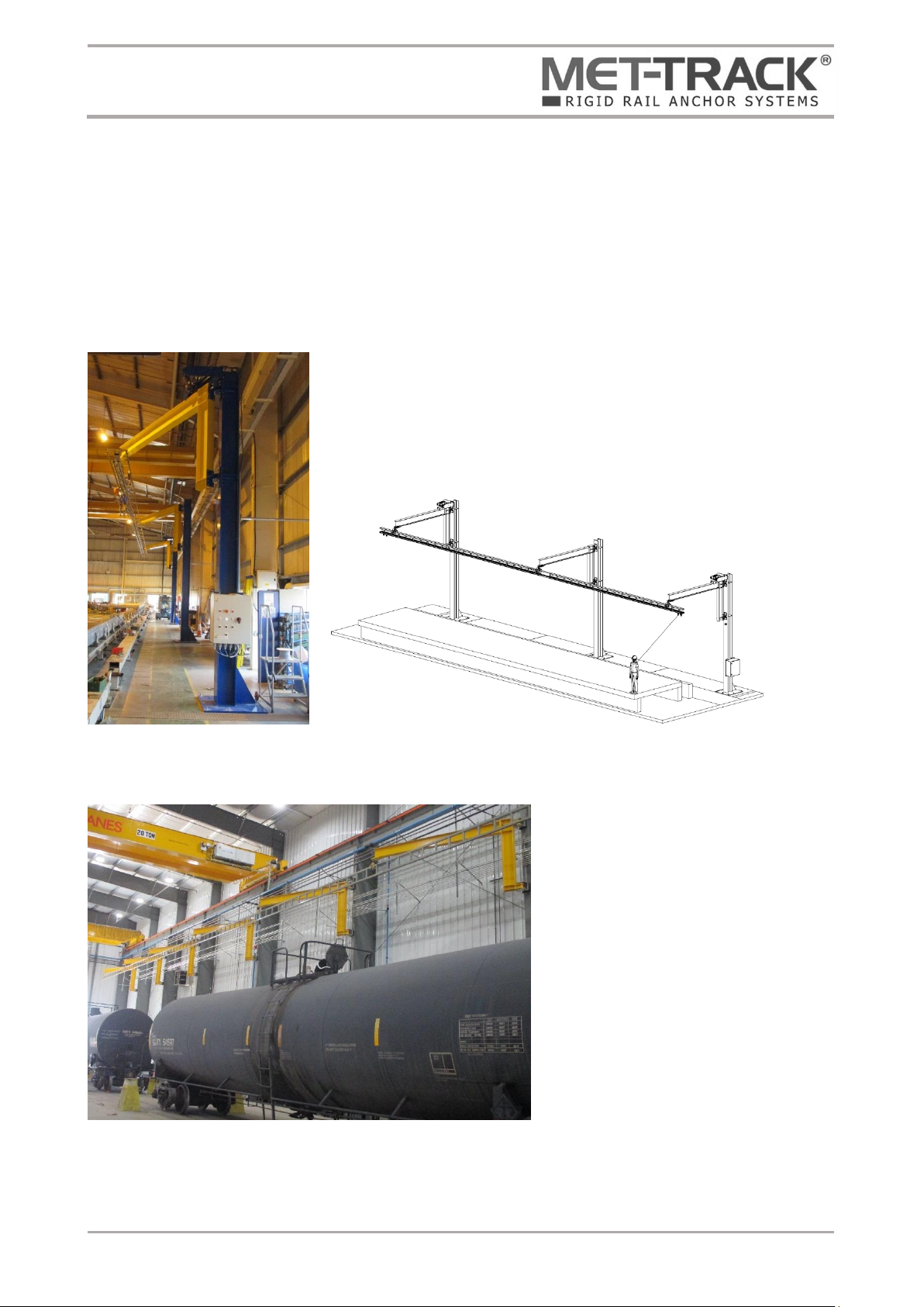
Floor Mounted Powered System
Floor mounted systems comprise of a complete system including
upright steelwork support posts which fix to existing reinforced
concrete floor slabs. The standard floor slab generally must be a
minimum 150mm deep C30/C35 grade reinforced wire mesh
concrete. Always check the general arrangement drawing to
confirm any changes to these requirements.
Post Mounted Powered System
Post mounted systems can be
supplied ready to attach to existing
building structures providing the
structure is of adequate strength. The
suitability of the structure must be
confirmed by a structural engineer.
All powered systems are fitted with
integral brakes within the drive motor
allowing the system to be used safety
anywhere within the agreed
operational area.
Foldaway Rigid Rail Anchor System
Installation & Maintenance Instructions
Document Ref. I&M175-0519
Last Updated: 08.05.19
Page 7of 38
Floor or Post Mounted Manual System
Floor and post mount systems can be suppled as a manual option. These can be retracted and
folded back manually by pulling the operating cables. Manual systems can be supplied as linked
arm or single arm. All manual systems must use slew locks to allow the arms to be secured before
use.

Foldaway Rigid Rail Anchor System
Installation & Maintenance Instructions
Document Ref. I&M175-0519
Last Updated: 08.05.19
Page 8of 38
Slew locking on manual systems
All manual systems must include slew locks to secure the jib arm before the fall arrest system is
used. Below details a typical locking mechanism.
These are not required on powered systems as these are locked by the integral brake fitted within
the drive motor.
Refer to project information supplied for further details on the units supplied.

Foldaway Rigid Rail Anchor System
Installation & Maintenance Instructions
Document Ref. I&M175-0519
Last Updated: 08.05.19
Page 9of 38
2.2 Installation of jib mounting post
If fixing to existing building structures this step is not required, refer to next step installation of jib
arms.
The floor should be marked out in accordance with the relevant general arrangement drawing.
Floor mounting positions should be carefully checked to make sure these are in alignment in both
x and y plains. It is recommended that the tolerance of alignment is a maximum of +/- 1mm.
The floor level should be confirmed using an optical level. The level tolerance of +/-5mm can be
accepted between all posts as the rail has minor adjustment. If this is exceeded the posts must be
packed using floor packing plates. These are not standard supply as it is assumed the floor is
adequate. Metreel recommend a survey is carried out and these ordered before installation if
required.
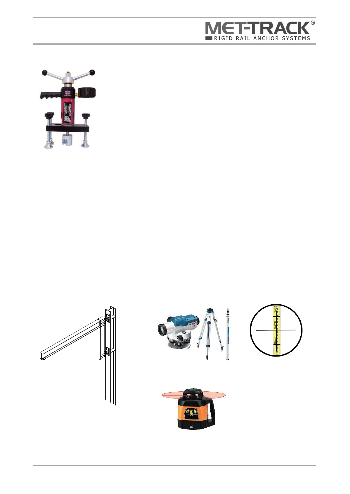
Once the floor is marked out the post should be positioned,
and the floor drilled using a heavy duty SDS drill to the
required depth as indicated on the GA. The drilled holes
should be thoroughly cleaned in accordance with fixing
manufacturers recommendations.
Metreel recommend Fisher injection mortar FIS V 360S. This
should be injected into the drilled holes and 8.8 grade
studding installed.
Once the resin has cured pull testing should be carried out
on each stud. Refer to Fisher data sheet for curing ambient
temperatures and times. Metreel recommend using an
approved calibrated anchor pull tester such as those
produced by Hydrajaws Limited. Refer to the general
arrangement drawing for the pull test kN rating.
Fixing nuts and washers should be fitted and tightened to
the correct torque. It is imperative the post is plum to avoid
the MET-TRACK® twisting when fitted.
Due to all systems being project specific the general arrangement drawing and any other technical
documentation supplied should be consulted to confirm actual minimum concrete strength,
studding size and embedment depth and pull test values. Resin types should also be double
checked against that recommended on the general arrangement drawing.
Typical jib mounting posts, illustration only
Foldaway Rigid Rail Anchor System
Installation & Maintenance Instructions
Document Ref. I&M175-0519
Last Updated: 08.05.19
Page 10 of 38
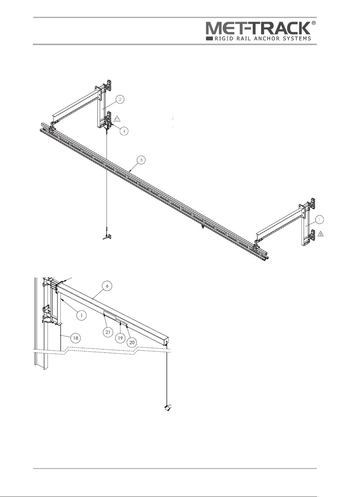
2.3 Installation of jib arm
Jib arms should be lifted up and fixed to the jib posts previously installed or the existing building
steelwork. If being fitted to building steelwork this will need to be marked out and drilled in
advance before the jib arms can be fixed in place. Before drilling any building steelwork Metreel
recommend marking all posts using an auto leveling rotary laser marker.
Important –Check the oilite bushes flanges are in position and undamaged on the hinge
assembly and that the split pin is fitted to the castle nut.
It is imperative that the jib arms are checked for level once installed as only minimum adjustment
is available during final installation. Metreel recommend using an optical level once all arms are
fitted to confirm arms are within +/-5mm.
All jib arms should be installed at 180 degrees from fixing posts to allow the MET-TRACK® to be
fitted at a later stage.
Typical Hydrajaw anchor pull tester
Used to confirm studding is correctly bonded
Typical optical level
Typical self-leveling
rotary laser level
Foldaway Rigid Rail Anchor System
Installation & Maintenance Instructions
Document Ref. I&M175-0519
Last Updated: 08.05.19
Page 11 of 38
Typical master slew drive
Self-adhesive Foam packing
Master drive proximity sensors
Foam packing
Master drive proximity sensors
Master drive proximity sensors
Slew drive arm
Jib arm
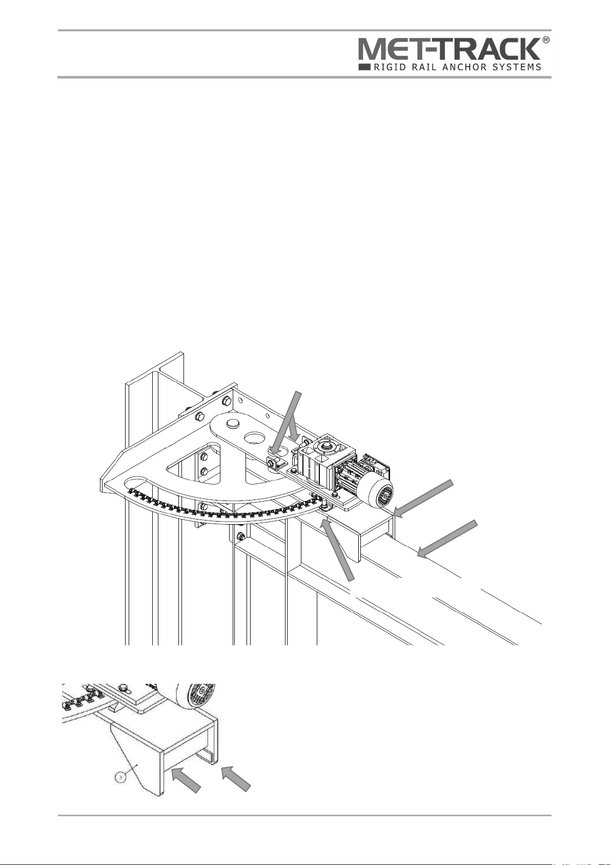
Installation of master and slave slew drive assembly
Two types of slew drives are provided. Drives should be lifted and secured to the post using 4x
set screws as detailed on the general arrangement drawing. Depending on the application not all
posts will be fitted with master or slave drive units.
Master slew drive –Powered unit fitted with a 3-phase induction motor which drives against a
chain rack creating drive arm movement. The master slew drive is fitted with proximity sensors
which are used to prevent overtravel. Only one master slew drive is provided for each system
which can be installed in any position where powered slew drives are used. This will allow the
user to mount the control panel in the most desirable location whilst minimising cabling between
the master slew drive and control panel.
Slew drives are supplied pre-assembled by Metreel. These should be lifted and fixed to the
relevant posts as indicated on the system general arrangement drawing making sure the drive arm
correctly fits over the jib arm.
In order to minimise float between the jib arm and slew
drive sponge parkers are supplied. These should be
fitted between the inside of the slew drive arm and the
jib arm. When correctly fitted the jib arm cannot be
freely moved by hand.

Foldaway Rigid Rail Anchor System
Installation & Maintenance Instructions
Document Ref. I&M175-0519
Last Updated: 08.05.19
Page 12 of 38
Slave slew drive –Powered and identical to the master drive however does not include proximity
sensors.
Non-driven arm –Dependent on the system being supplied not all arms will be power driven,
refer to the general arrangement drawing for details.
Lubrication
The tug chain drive assembly should be lubricated with a dry chain lubricant such as ‘Ambersil FLT
Chainlube’ applied every 12 months.
Final arm adjustment
Once all brackets are fitted dimensions should be checked between the jib arm pivot point center
and support bracket center, making sure all arms are identical. If adjustment is required, the
slotted support plate can be loosened and moved forward/back to suit. As only minimal
adjustment is available within the slots posts and arms must have been installed as previously
described, failure to do so may result in insufficient adjustment being available.
To adjust the support plate, loosen x4 set screws and slide to the required position. Once in place
retighten screws to the correct torque value.

Foldaway Rigid Rail Anchor System
Installation & Maintenance Instructions
Document Ref. I&M175-0519
Last Updated: 08.05.19
Page 13 of 38
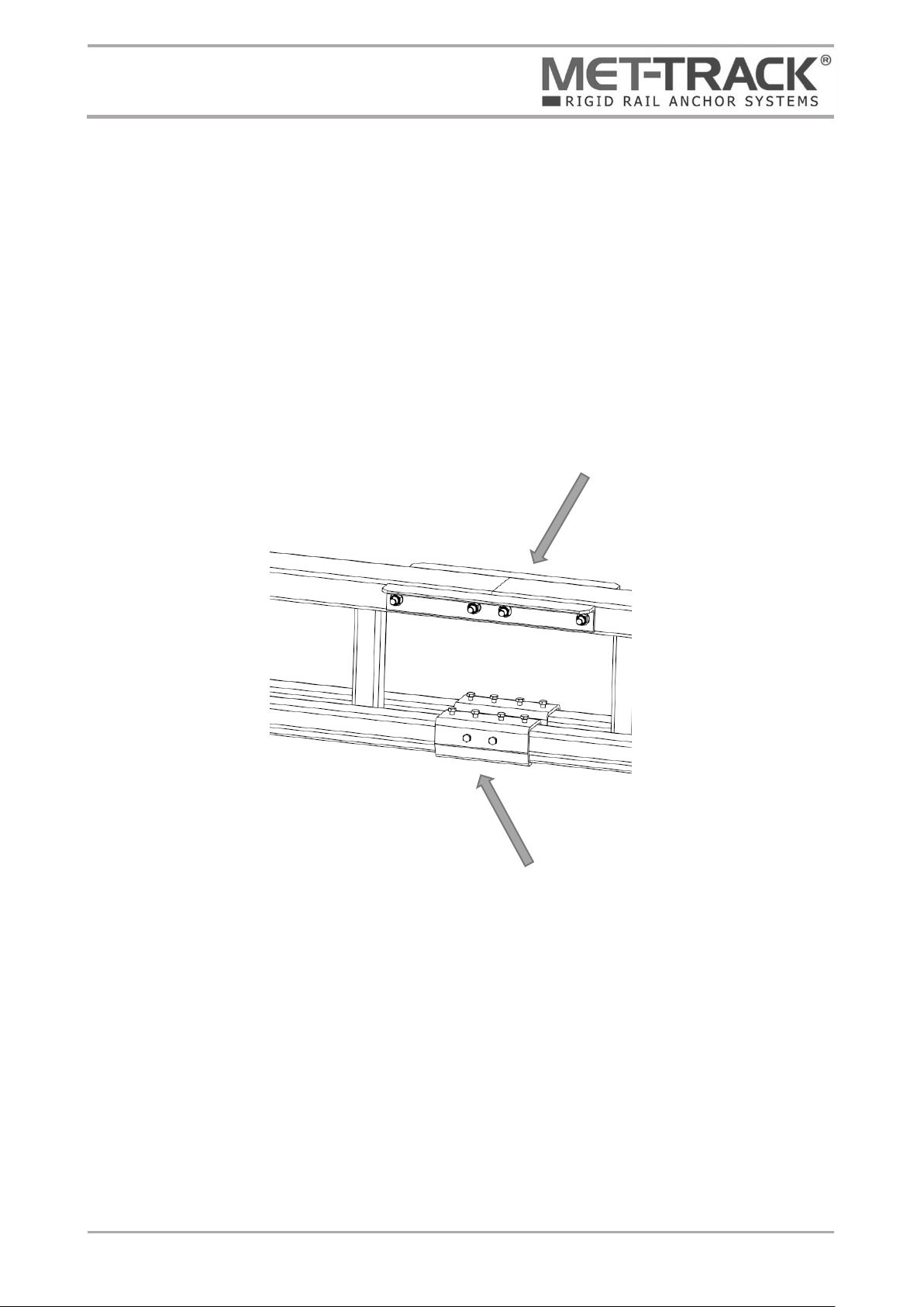
Installation of runway sections
Rail sections should be lifted up and fixed to their relevant support arm, refer to the general
arrangement drawing to confirm the section positions. Start with the longest rail section which will
span between the two of the jib arms, this should be lifted up and fixed using the jib arm rail
brackets.
Foldaway Rigid Rail Anchor System
Installation & Maintenance Instructions
Document Ref. I&M175-0519
Last Updated: 08.05.19
Page 14 of 38
Remaining sections can be installed as the first joining the sections by using rail section joint kits
as illustrated below.
The splice joint is a sleeve with eight set screws fitted into the top and both sides. Slide the sleeve
over the end of the first rail, then butt the second rail against the first. Centre the sleeve over the
joint. The four top set screws should be tightened until the tracks are pushed against the base of
the sleeve so that the two bottom surfaces of the track are in line see fig.2b. The side set screws
should then be tightened so that the rail slots are aligned and there is a smooth transition from
one rail to the other, see fig. 2c. Torque values cannot be given for this procedure as this is
dependent on the level of adjustment required. It is important to fully tighten the top screws first.

Foldaway Rigid Rail Anchor System
Installation & Maintenance Instructions
Document Ref. I&M175-0519
Last Updated: 08.05.19
Page 15 of 38
Before fitting the splice joint for the MET-TRACK®profile ends should be prepared by rounding
off the sharp edges of the running flanges of the profile, see fig. 2a
Correct Alignment –Top View
Top screws - Correct Alignment (Side View)
Fig 2c
Incorrect Alignment –Top View
Top screws –Incorrect Alignment (Side View)
Radius Edges
Fig 2b
Fig 2a
Foldaway Rigid Rail Anchor System
Installation & Maintenance Instructions
Document Ref. I&M175-0519
Last Updated: 08.05.19
Page 16 of 38
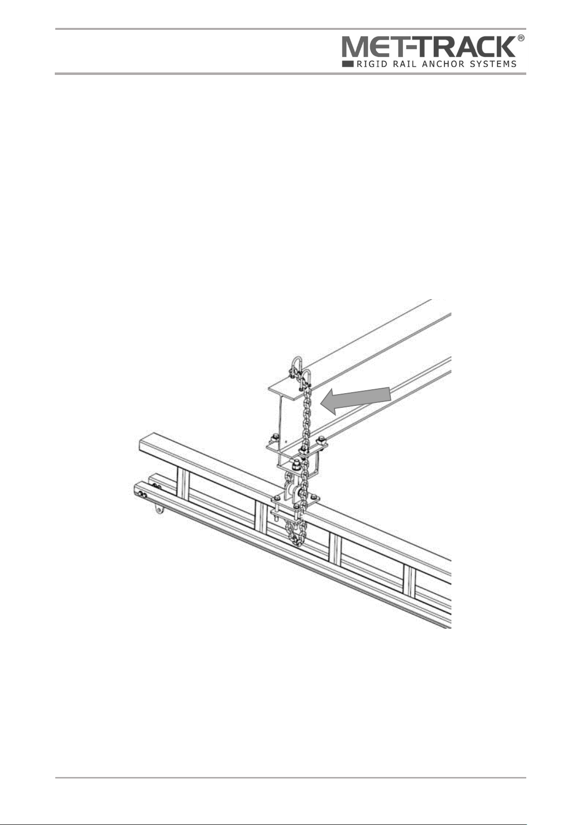
Installation of safety chains
Secondary restraint safety chains are supplied which must be installed around the jib arm and
runway weldment (refer to detailed project drawings supplied with the equipment for further
installation details).
It is vital chains are correctly installed to provide adequate secondary restraint should the single
pivot pin fail. A small amount of free movement must be allowed when installing the safety chain
to allow movement between the jib arm and rail connection bracket.
Foldaway Rigid Rail Anchor System
Installation & Maintenance Instructions
Document Ref. I&M175-0519
Last Updated: 08.05.19
Page 17 of 38
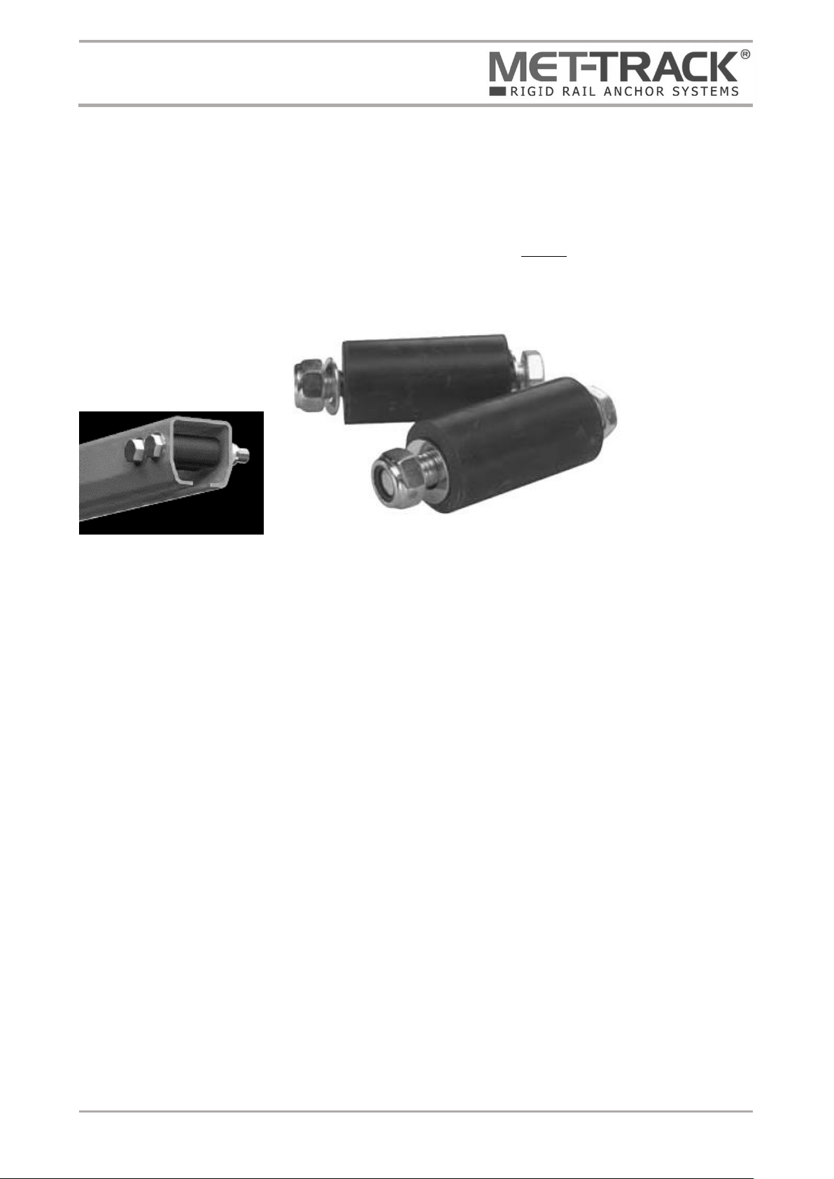
Rail end stops
The rail section ends must be fitted with two end stops.
The ends of the track should be pre-drilled to accept stops. The rubber absorber should be slide
down the track end then the bolt pushed through. Stops should always be fixed in place using flat
washers and nylock nuts. Two stops should be fitted the second acting as redundancy.
Foldaway Rigid Rail Anchor System
Installation & Maintenance Instructions
Document Ref. I&M175-0519
Last Updated: 08.05.19
Page 18 of 38
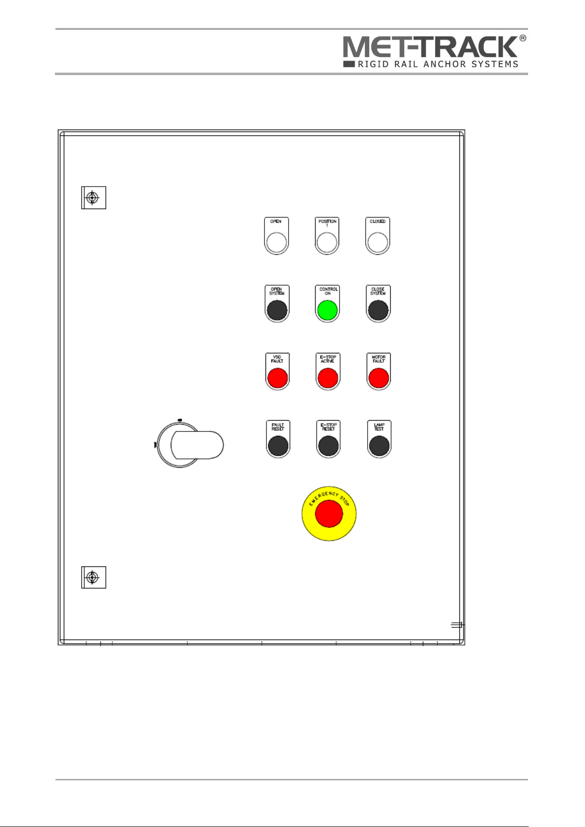
MMCP General Arrangement

Foldaway Rigid Rail Anchor System
Installation & Maintenance Instructions
Document Ref. I&M175-0519
Last Updated: 08.05.19
Page 19 of 38

Foldaway Rigid Rail Anchor System
Installation & Maintenance Instructions
Document Ref. I&M175-0519
Last Updated: 08.05.19
Page 20 of 38
2.4 MMCP Installation
a) It is assumed that the mechanical installation of the Foldaway RRAS has been completed prior
to the installation of the control system.
b) Unpack the panel and check for any damage.
c) Control panel wall mounting brackets are not fitted to the control panel to avoid damage during
transit. These should be fitted to the corners of the control panel through the holes provided
within the enclosure. Brackets and fixings are included and packed inside the control panel.
d) Securely mount the control panel to the wall or suitable structure. Fixing screws between
mounting brackets and support structure are not provided by Metreel.
e) Cables should be run between relevant components and the control panel. Metreel do not
supply interfacing cables unless requested. Guidance of cables to be used can be found within
this document under section 2.5 recommendation for motor field cables.
Reference should be made to electrical wiring schematics ED9130 and relevant cable schedules.
Metreel advise that the motor feed cables be of a screened construction to minimise EMF
interference caused from VSD controller within the control panel. Reference section 2.3 for
further details. The motor brake should be connected with a separate cable, Metreel do not
advise using single multicore cable controlling both motor and brake due to interference.
f) The control panel gland plate should be removed from the panel before being marked out and
drilled in accordance to the field wiring running back to the control panel. Glands should be
fitted (not supplied) and the gland plate refitted. Failure to remove the gland plat prior to
drilling may interduce debris into the enclosure.
g) Proximity sensors should be fitted to the master drive arm per Mechanical installation drawings.
Interface cables will require the sensor end being pre fitted with a M12 type connector
h) All field cables should be run between relevant components and connected in accordance with
ED9130.
Other manuals for MET-TRACK
1
Table of contents
Other Metreel Construction Equipment manuals


Popular Construction Equipment manuals by other brands

Neilsen
Neilsen CT0949 Original instructions

Farmi Forest
Farmi Forest CR67 OPERATION, MAINTENANCE AND SPARE PARTS MANUAL

tekton
tekton 6519 Operator's manual

Knauf PFT
Knauf PFT SWING L FC 230V operating manual

Clarke
Clarke WOODWORKER CTS17 Operation & maintenance instructions

Grizzly
Grizzly H5502 instruction manual


